Table of Contents

Subscribe to Our Youtube Channel
Related Manuals for Vitrek V4


Summary of Contents for Vitrek V4
-
Page 1: Operating Manual
® Advanced Test Equipment Rentals www.atecorp.com 800-404-ATEC (2832) V4 Electrical Safety Analyzer AC/DC/IR/GB Operating Manual Valid for all units S/N 14210 and up 99 Washington Street Melrose, MA 02176 Fax 781-665-0780 TestEquipmentDepot.com... - Page 2 Vitrek to have been caused by abuse, misuse, alteration, improper installation, neglect or adverse environmental conditions. Vitrek...
-
Page 3: Table Of Contents
Vitrek V4 – Electrical Safety Tester USER MANUAL TABLE OF CONTENTS PAGE 1. PRODUCT INTRODUCTION......….. 1-1. Description…………………………..………... 1-2. Feature………………………………….……... 2. SPECIFICATIONS………………………………... 7 3. PRECAUTIONS BEFORE OPERATION…….… 3-1. Unpacking the Instrument……..…………….. 3-2. Safety Notice………………..…………………. 3-3. Environment…………………………….……. 4. PANEL INTRODUCTION……………………..… 4-1. Front Panel……………………………………. -
Page 4: Product Introduction
1. V4 PRODUCT INTRODUCTION Our goal at Vitrek is 100% customer satisfaction with both our products and our people. Please fill free to contact us if we can be of help with application or technical assistance, repair or calibration services accessories or spare parts. - Page 5 Vitrek V4 – Electrical Safety Tester USER MANUAL 3) Easily and quickly setup by front panel A user-friendly interface provides user an easy and quick way to set all parameters. 4) Electronic ramping and testing Digital controlled ramping time and testing time.
-
Page 6: Specifications
Vitrek V4 – Electrical Safety Tester USER MANUAL 2. VITREK V4 FOUR IN ONE SAFETY TESTER SPECIFICATIONS 1) AC Hi-Pot Specifications: Voltage Range 0.100~5.000kV Voltage Step 5V/step Voltage Regulation 1% + 5V (line & load) Voltage Accuracy 1% of reading +10V Current Sourcing*... - Page 7 Vitrek V4 – Electrical Safety Tester USER MANUAL Ground Bond Test Time 000.0~999.9s 6) ARC Detect Detect Current 40 level (1~40mA) 7) Storage Groups Steps 8) Interface RS-232 Standard GPIB Option 9) PLC Control D-sub 9 pins female Standard 10) Scanner Interface...
- Page 8 Vitrek V4 – Electrical Safety Tester USER MANUAL Operating Environment: Indoor use, Altitude up to 6500ft (2000m). Installation Category II. Pollution Degree 2 Operating Temperature: 0°C to 40°C, 80% RH max. Storage Temperature: -10°C to 70°C, 70% RH max Dimension: 17.6”L x 13”W x 5.9”H, 446(L) x 330(W) x 149(H) mm...
-
Page 9: Precautions Before Operation
The product has been fully inspected and tested before shipping from the factory. Upon receiving the instrument, please unpack and inspect it for any damage that may have occurred during transportation. If any sign of damage is found, notify the carrier and Vitrek or your distributor immediately. 3-2. Safety Notice... -
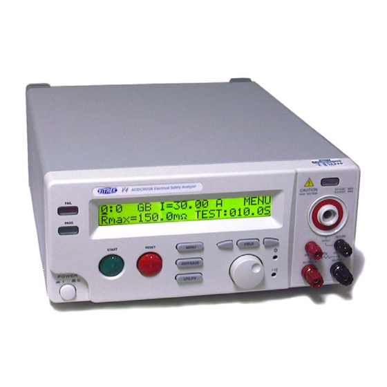
Page 10: Panel Introduction
Vitrek V4 – Electrical Safety Tester USER MANUAL Do not use the instrument in a place where a strong magnetic or electric field exists, as they may distort the measurements. 4. PANEL INTRODUCTION 4-1. Front Panel 1 Model Number Model number and description... -
Page 11: Rear Panel
Vitrek V4 – Electrical Safety Tester USER MANUAL 22 SENSE- & Return SENSE- Terminal is a voltage terminal for Ground Bond test, and Return Terminal is Terminal for all test. 4-2. Rear Panel 23 Ground Terminal Connect Ground terminal to the earth ground. -
Page 12: Main Lcd Display
Vitrek V4 – Electrical Safety Tester USER MANUAL 5. OPERATION METHOD 5-1. Main Display LCD Storage Mode Output Voltage/Current Status 1 ~ 0 1 A C W V = 5 . 0 0 0 k V * R E A D Y I m a x = 0 1 . -
Page 13: Preparing The Est For Use
Vitrek V4 – Electrical Safety Tester USER MANUAL Ramp/Test Ramp time and test time Time voltage AC: Ramp/Test (000.0~999.9 s) DC: Ramp/Test (000.0~999.9 s) IR: Test (001.0~999.9 s) time GB: Test (000.0~999.9 s) ramp test CNT: Test (000.0~999.9 s) CHANNEL Any of the channels can be selected from the Scanner Box for output. - Page 14 Vitrek V4 – Electrical Safety Tester USER MANUAL To Edit/Save the Storage Steps 1. Follow the above procedure “To View the Storage Steps “ to select a step. 2. Press the EDIT/SAVE key to enter status EDIT. E D I T EDIT/SAVE 3.
- Page 15 Vitrek V4 – Electrical Safety Tester USER MANUAL To Begin a Group Test 1. Repeat the procedure “To View the Storage Steps” to select a step. 2. Press RESET button to enter status READY. R E A D Y RESET 3.
- Page 16 Vitrek V4 – Electrical Safety Tester USER MANUAL 7. If the result is fail, the FAIL LED will be active and the buzzer will alarm operator. To stop the alarm, press RESET button again. F A I L RESET 8. Use knob to view the result of group step by step.
- Page 17 Vitrek V4 – Electrical Safety Tester USER MANUAL Table of System Utility: Parameter Option Description The group test procedure always begins from step 1 to end of group. From STEP 1 (e.g. 01~01) GROUP TEST The group test procedure always begins from the step selected to end...
- Page 18 Vitrek V4 – Electrical Safety Tester USER MANUAL GROUP TEST DATA INTERFACE FAIL TEST MODE CURRENT FREQ CONTROL LOCK MODE ZERO SETTING To Edit/Save the System Utility 1. Follow the above procedure “To View the System Utility” to select a parameter.
- Page 19 Vitrek V4 – Electrical Safety Tester USER MANUAL 5-3. Structure of Storage Steps The storage steps of EST are total 10 groups (group 0 ~ group 9), 16 steps (step 1 ~ step 16) for each group. Except these steps, there is another step “COM” for special test. The presentation of storage steps is Group: Step.
-
Page 20: Menu Parameter Setup & Operation
Vitrek V4 – Electrical Safety Tester USER MANUAL 5-4. Menu Parameter Setup AC/DC Hipot – Voltage withstand test (ACW/DCW) Press MENU key to enter MENU mode then use knob and arrow keys to select a step. Press EDIT/SAVE key to enter EDIT mode. The cursor stays at the “test mode” field. Use knob to select desired test ACW (DCW). - Page 21 Vitrek V4 – Electrical Safety Tester USER MANUAL Insulation Resistance test (IR) Press MENU key to enter status MENU then use the knob and Use arrow keys to select a step. Press EDIT/SAVE key to enter status EDIT. Now the cursor stays at the “test mode” field. Use the knob to select IR mode.
- Page 22 Vitrek V4 – Electrical Safety Tester USER MANUAL • Ground Bond test (GB) Press MENU key to enter status MENU then use the knob and arrow keys to select a step. Press EDIT/SAVE key to enter status EDIT. Now the cursor stays at the “test mode” field. Use the knob to select mode GB.
-
Page 23: Remote Interface Operation
5-5. Remote Interface Operation For ease of automating the V4 unit when interfacing to a PC, we recommend the use the Vitrek QT50 test automation software and PC interface adaptor. The adaptor allows you to control the unit via a standard PC serial or parallel port, while the software allows for the development of test sequences and the storage of all test results for viewing or export to a database. -
Page 24: Measurement Connections
Vitrek V4 – Electrical Safety Tester USER MANUAL 6. MEASUREMENT CONNECTIONS ACW, DCW and/or IR Test Connections Terminal 1 shown above is the High Voltage Output Terminal. This large HV connector with a red circle around it is the output terminal for all HV tests (ACW, DCW and IR). For typical electrical safety testing, this terminal connects to both the line and neutral power pins of the device under test (DUT). -
Page 25: Programming
7. PROGRAMMING 7-1. Introduction The Vitrek V4 Electrical Safety Tester (EST) is a fully interactive automatic measurement system. Communication between the V4 and host computers is easily accomplished. The V4’s standard RS232 interface or optional GPIB interface provide the capability to download and run a custom test sequence, as well as, monitor the status of the test and retrieve results and actual readings. - Page 26 Do not use loop or parallel structure for the topology of GPIB system. Computer’s Connection A personal computer with a GPIB card is the essential facilities in order to operate the V4 via GPIB interface. The connections between power supply and computer are following: 1.
- Page 27 Vitrek V4 – Electrical Safety Tester USER MANUAL Vitrek, V4, FW1.00 If you do not receive a proper response from the EST, please check if the power is on, the GPIB address is correct, and all cable connections are active.
-
Page 28: Connecting The V4 Via The Rs232 Interface
The EST is a DTE device with a 9-pin D-type shell RS232 connector located on the rear panel. Figure 1 shows the equipment of 9-pin connector (male) with its pin number assignments. Figure 2 shows the wiring configuration for DB9 to DB9. When the V4 is set up with a RS232 interface, please check the following points: Do not connect the output line of one DTE device to the output line of the other. -
Page 29: Input And Output Queue
Pin5 Computer’s Connection A personal computer with a COM port is the essential facilities in order to operate the V4 via RS232 interface. The connections between EST and computer are as follows: 1. Connect one end of a RS232 cable to the computer. - Page 30 Vitrek V4 – Electrical Safety Tester USER MANUAL syntax has been adopted by SCPI to provide common commands for the identical functions of different programmable instruments. SCPI Common Command & Queries Syntax & Status Data Structure Interface Function SCPI IEEE-488.1 SCPI IEEE-488.2...
- Page 31 Figure 6 includes the Boolean parameter type. NOTE: Do not include the <, >, or | symbols when entering the actual value for a parameter. Figure 6 Command Header with Parameter Table 1 defines the Boolean and other parameter types for the V4.
- Page 32 Entering Commands The standards that govern the command set for the V4 allow for a certain amount of flexibility when you enter commands. For instance, you can abbreviate many commands or combine commands into one message that you send to the V4. This flexibility, called friendly listening, saves programming time and makes the command set easier to remember and use.
- Page 33 Vitrek V4 – Electrical Safety Tester USER MANUAL Combining Commands You can use a semicolon (;) to combine commands. But continuously query command will cause message missing. For example :GRO:STEP: ACWS:VOLT:;CMAX? If the command that follows the semicolon has a different header path from the root level, you must use a colon to force a return to the root level.
- Page 34 Vitrek V4 – Electrical Safety Tester USER MANUAL :UTILity:ARC:MODe? Query the ARC test mode :UTILity:TEST:MODe <NR1> Set the test mode from step 1 or form present setp :UTILity:TEST:MODe? Query the test mode :UTILity:IRTest:MODe <NR1> Set the value of IR test mode...
- Page 35 Vitrek V4 – Electrical Safety Tester USER MANUAL :DCWStanding:CMINimum <NR2> Set the DCW test minimum current :DCWStanding:CMINimum? Query the DCW test minimum current :DCWStanding:CMAXimum <NR2> Set the DCW test maximum current :DCWStanding:CMAXimum? Query the DCW test maximum current :DCWStanding:RTIMe <NR2>...
- Page 36 Vitrek V4 – Electrical Safety Tester USER MANUAL Enable Register (SRER). *STB? Reads Status Byte Register (SBR). :STATus:OPERation:CONDition ? Returns the contents of the OPERation condition register. Returns NR1. :STATus:OPERation:ENABle <NR1> Sets the contents of the enable mask for the OPERation event register.
-
Page 37: Details Of Command Reference
Vitrek V4 – Electrical Safety Tester USER MANUAL 7-6. Details of Command Reference Each command in this chapter will give a detailed description. The examples of each command will be provided and what query form might return. *CLS (no query form) Function: Clear all event status data register. - Page 38 The command form (*OPC) sets the operation complete bit (bit 0) in the Standard Event Status Register (SESR) when all pending operations are finished. The query form (*OPC?) tells the V4 to place an ASCII 1 in the Output Queue when the power supply completes all pending operations.
- Page 39 Vitrek V4 – Electrical Safety Tester USER MANUAL *SAV Function: Save the setting data to a specific memory location. Syntax: *SAV <NR1> <NR1> is in the range from 0 through 99. Examples: *SAV 01 - saves the current setting data to memory location 1.
- Page 40 Vitrek V4 – Electrical Safety Tester USER MANUAL *WAI (no query form) Function: WAI prevents the programming instrument from executing further commands or queries until all pending operations are finished. Syntax: *WAI :GROup Function: Set or query the value of group.
- Page 41 Vitrek V4 – Electrical Safety Tester USER MANUAL :FUNCtion:TEST:STATe Function: Set or query the test state ( 0:OFF 1:ON 2:CONTINUE) Syntax: :FUNCtion:TEST:STATe <NR1> :FUNCtion:TEST:STATe? <NR1> is in the range from 0 through 2. Return: <NR1> Examples: :FUNCtion:TEST:STATe 1 - start test.
- Page 42 Vitrek V4 – Electrical Safety Tester USER MANUAL V/I: Test Function (5 bytes) Unit (2 bytes) HOLD PAUSE Meas: Test Function (5 bytes) Unit (4 bytes) MΩ mΩ HOLD Time: Time (1 byte) Value (5 bytes) Unit (1 byte) Ramp 005.0...
- Page 43 Vitrek V4 – Electrical Safety Tester USER MANUAL :UTILity:ARC:CURRent Function: Set or query the ARC current Syntax: :UTILity:ARC:CURRent <NR2> :UTILity:ARC:CURRent? <NR2> is in the integer range 1 to 40 mA Return: <NR2> Examples: :UTILity:ARC:CURRent 2 - sets the ARC current to 2.00mA.
- Page 44 Vitrek V4 – Electrical Safety Tester USER MANUAL :UTILity:IRTest:MODe Function: Set or query the IR test mode ( 0:Stop on Fail, 1:Stop on Pass, 2:TIMER ) Syntax: :UTILity:IRTest:MODe <NR1> :UTILity:IRTest:MODe? <NR1> is in the range from 0 through 2. Return: <NR1>...
- Page 45 Vitrek V4 – Electrical Safety Tester USER MANUAL :ACContinuous:CMINimum Function: Set or query the CAC test minimum current. Syntax: :ACContinuous:CMINimum <NR2> :ACContinuous:CMINimum? <NR2> Please refer to the specification Return: <NR2> Examples: :ACContinuous:CMINimum 1.00 - sets the CAC test minimum current to 1.00mA.
- Page 46 Vitrek V4 – Electrical Safety Tester USER MANUAL :DCContinuous:VOLTage Function: Set or query the CDC test voltage. Syntax: :DCContinuous:VOLTage <NR2> :DCContinuous:VOLTage? <NR2> Please refer to the specification Return: <NR2> Examples: :DCContinuous:VOLTage 1.000 - sets the CDC test voltage to 1.000kV.
- Page 47 Vitrek V4 – Electrical Safety Tester USER MANUAL :DCContinuous:RTIMe Function: Set or query the CDC ramp time. Syntax: :DCContinuous:RTIMe <NR2> :DCContinuous:RTIMe? <NR2> Please refer to the specification Return: <NR2> Examples: :DCContinuous:RTIMe 5.0 - sets the CDC ramp time to 5 sec.
- Page 48 Vitrek V4 – Electrical Safety Tester USER MANUAL :ACWStanding:CMAXimum Function: Set or query the ACW test maximum current. Syntax: :ACWStanding:CMAXimum <NR2> :ACWStanding:CMAXimum? <NR2> Please refer to the specification Return: <NR2> Examples: :ACWStanding:CMAXimum 1.00 - sets the ACW test maximum current to 1.00mA.
- Page 49 Vitrek V4 – Electrical Safety Tester USER MANUAL :DCWStanding:VOLTage Function: Set or query the DCW test voltage. Syntax: :DCWStanding:VOLTage <NR2> :DCWStanding:VOLTage <NR2> Please refer to the specification Return: <NR2> Examples: : DCWStanding:VOLTage 1.000 - sets the DCW test voltage to 1.000kV.
- Page 50 Vitrek V4 – Electrical Safety Tester USER MANUAL :DCWStanding:RTIMe Function: Set or query the DCW ramp time. Syntax: :DCWStanding:RTIMe <NR2> :DCWStanding:RTIMe <NR2> Please refer to the specification Return: <NR2> Examples: :DCWStanding:RTIMe 5.0 - sets the DCW ramp time to 5 sec.
- Page 51 Vitrek V4 – Electrical Safety Tester USER MANUAL :IRESistance:RMINimum Function: Set or query the IR test minimum resistance. Syntax: :IRESistance:RMINimum <NR1> :IRESistance:RMINimum <NR1> Please refer to the specification Return: <NR1> Examples: :IRESistance:RMINimum 100 - sets the IR test minimum resistance to 100MΩ.
- Page 52 Vitrek V4 – Electrical Safety Tester USER MANUAL :GBONd:CURRent Function: Set or query the GB test current. Syntax: :GBONd:CURRent <NR1> :GBONd:CURRent? <NR1> Please refer to the specification Return: <NR1> Examples: :GBONd:CURRent - 25 sets the GB test current to 25A.
- Page 53 Vitrek V4 – Electrical Safety Tester USER MANUAL :GBONd:TTIMe Function: Set or query the GB test time. Syntax: :GBONd:TTIMe <NR2> :GBONd:TTIMe? <NR2> Please refer to the specification Return: <NR2> Examples: :GBONd:TTIMe 5.0 - sets the IR test time to 5 sec.
-
Page 54: Status And Error Reporting
Vitrek V4 – Electrical Safety Tester USER MANUAL 7-7. Status and Error Reporting A set of status registers allows the user to quickly determine the EST’s internal processing status. The status register, as well as the status and event reporting system, adhere to SCPI recommendations. - Page 55 Vitrek V4 – Electrical Safety Tester USER MANUAL Figure 8: Status registers and related commands To SBR Event Enable Condition Register Register Register The CONDition register is a read-only register which monitors the present state of the instrument. The CONDition register updates in real time and the inputs are not latched or buffered. When a condition monitored by the CONDition register becomes true, the bit for that condition also becomes true (1).
- Page 56 Vitrek V4 – Electrical Safety Tester USER MANUAL There are two status registers are included to the EST defined by IEEE-488.1 and IEEE-488.2 standards. 1. Status Byte Register (SBR) 2. Standard Event Status Register (SESR) Status Byte Register (SBR): The SBR (Table 6) summarizes the status of all other registers and queues.
- Page 57 Use the *ESE command to set the bits in ESER. Use the *ESE? query to read it. • OPERation Enable Register: Even though the OPERation Enable Register is present in the V4’s, the OPERation registers do not report any conditions.
- Page 58 Vitrek V4 – Electrical Safety Tester USER MANUAL -222,"Data out of range;" -222,"Data out of range; Timer too large" -222,"Data out of range; Voltage too large" -222,"Data out of range; Current too large" -222,"Data out of range; Resistance too large"...
-
Page 59: Fuse Rating And Type
Vitrek V4 – Electrical Safety Tester USER MANUAL 8. MAINTENANCE Only a qualified person should use the following instructions in order to avoid electrical shock. Do not perform any service other than contained in the operation instructions unless you are qualified to do so. -
Page 60: V4 Calibration Procedure
The following procedure will provide verification of the calibration status of the Vitrek V4 EST. Utilize the attached V4 calibration data sheet for verification sequence, nominal values and maximum allowable tolerance. Not all units in the V4 have all functions. Omit test points for any given unit where dashes are shown. - Page 61 The following portion of this procedure is for adjustment of the actual calibration values. The Vitrek V4 ESTs can be divided into several modules for calibration & adjustment. The modules consist of: main board, isolation board, AC withstanding voltage, DC withstanding voltage, IR, and Ground Bond.
- Page 62 Vitrek V4 – Electrical Safety Tester USER MANUAL 4. Repeat step 3 for “3000V”. If desired, you can repeat from step 2 with the other frequency (50 or 60 Hz). 5. After calibration of 4 sets voltage is finished, the LCD monitor will go back to the original display. Press the left &...
- Page 63 Vitrek V4 – Electrical Safety Tester USER MANUAL voltage- current adjustment procedure” are similar. Connect a 1.2MΩ /50W resistor with DMM (on the range of DC current 20mA) and EST in series. Switch the EST to “DCI” module and press “START” key to calibrate “DC 0.5mA”...
- Page 64 STEP 6: Ground Bond Current Adjustment (STEP 6: GB) Connect current shunt (100mΩ, 100A) with a voltage meter (on the range of DC mV) and V4. Switch the EST to "STEP6: GB I" module and press "START" key to calibration " GB I 3A","GB I 40A"...
Need help?
Do you have a question about the V4 and is the answer not in the manual?
Questions and answers