
Related Manuals for Tecnoinox B8FXEN9


Summary of Contents for Tecnoinox B8FXEN9
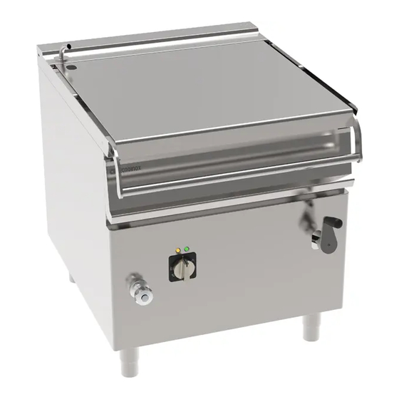
- Page 1 CODE 316192 MODEL B8FXEN9 DESCRIPTION FREESTANDING 80LT ELECTRIC TILTING BRAT T PAN WITH STAINLESS STEEL TANK ON CLOS ED CABINET 06-03-2023 12:06...
- Page 2 INSTRUCTION MANUAL FOR INSTALLATION, MAINTENANCE AND USE RECTANGULAR BRATT PANS ELECTRIC TYPE “B8FXEN9 - B8MFXEN9” “B8FIEN9 - B8MFIEN9” “B12FXEN9 - B12MFXEN9” “B12FIEN9 - B12MFIEN9”...
-
Page 3: Table Of Contents
TABLE OF CONTENTS GENERAL REMINDERS AND NOTES ....................3 Introduction ............................3 Simbols and pictograms........................3 General reminders ..........................3 Construction ............................4 Laws, technical prescriptions and directives ..................4 Special requirements for the installation site ..................5 Technical data ............................. 6 Electrical specifications (non standard voltages) ................. -
Page 4: General Reminders And Notes
GENERAL REMINDERS AND NOTES INTRODUCTION The heads of business units, where the unit will be installed, have an obligation, in accordance with the regulations, read carefully the contents of this manual and read the operators and maintainers involved for parts that they compete. This manual includes all the information necessary to ensure that our equipment can be used properly and safely. -
Page 5: Construction
− Unplug the appliance in case of failures or improper operation. − Apply exclusively to a service centre for repairs or maintenance. − Any important information about the appliance required for technical service is contained in the technical data plate (see figure “View of appliance”). −... -
Page 6: Special Requirements For The Installation Site
− the regulations of the electrical power supply company or agency; − any other local prescriptions. SPECIAL REQUIREMENTS FOR THE INSTALLATION SITE − The room in which the appliance is to operate must be well ventilated. − In addition, it is good policy to locate the appliance under an extractor hood so that cooking vapours can be removed rapidly and continuously. -
Page 7: Technical Data
TECHNICAL DATA B8FXEN9 - B8MFXEN9 B12FXEN9 - B12MFXEN9 B8FIEN9 - B8MFIEN9 B12FIEN9 - B12MFIEN9 TECHNICAL DATA (DIMEMSIONS) Equipment dim.A 1200 Equipment dim.B Equipment dim.H Equipment dim.H2 1630 1630 TECHNICAL DATA (FUNCTIONALITY) Pan dimension A 1098 Pan dimension B Pan dimension H Pan area dm²... -
Page 8: Electrical Specifications (Non Standard Voltages)
ELECTRICAL SPECIFICATIONS (NON STANDARD VOLTAGES) B8FXEN9 - B8MFXEN9 - B8FIEN9 - B8MFIEN9 Voltage Electric power Current Power cable nr. x mm² 380-415 V 3 ~ 15,1 4 x 2,5 220-240 V 3 ~ 26,2 4 x 6 208 V 3 ~... -
Page 9: Positioning, Installation And Maintenance
POSITIONING, INSTALLATION AND MAINTENANCE POSITIONING − Remove all the packaging and check that the appliance is in perfect conditions. In case of visible damage, do not connect the appliance and notify the sales point immediately. − Remove the PVC protection from the panels. −... -
Page 10: Connection To Waterworks
− The cable must be fed in from beneath the clamp. The individual wires are then fastened to the corresponding terminals of the terminal board. The earth wire must be longer than the other wires, so that in the event of the cable being jerked or the clamp broken, the live wires will disconnect first. Lock the cord fastener. -
Page 11: Maintenance Of The Appliance
MAINTENANCE OF THE APPLIANCE All maintenance operations shall only be performed by a technically qualified service centre! − To ensure correct and safe operation, the appliance must be inspected and serviced at least once a year only. Maintenance includes also controlling the components and tear of pipes, feeding pipes, electrical components etc. -
Page 12: Possible Failures And Their Elimination
2) Check the panels coupling, they must be perfectly closed with all screws. 3) Check water supply seal (water filling tap). 4) Verification closing terminals of electrical parts connections. Cleaning of electrical parts. 2.4.2 POSSIBLE FAILURES AND THEIR ELIMINATION Only a qualified technical assistance service can intervene as specified below! Before resetting the safety thermostat always remove the cause that caused your intervention! EVENT AND POSSIBLE DEFECT... - Page 13 Place the two bulbs of the thermostats in the special quarries (1), make sure that they are completely threaded to the end, curve the capillaries, respecting minimum R 20mm. Lock the bulbs with the retaining bracket (2). Caution: do not crush the capillary in the closed phase of the bracket (2). Check that the bulbs do not move from the starting Position.
- Page 14 − Return the part. B towards the front zone, bringing the screws 2 back to pos. 2.1. and close Them. (DIS. 1) − Close the part. C and return the screw (3) to Pos. 3.1. (DIS. 1) − (α = 30 °) −...
- Page 15 RECTANGULAR BRATT PANS ELECTRIC TYPE “BR8E080I - BR8E080I.M” “BR9E090I – INSTRUCTION MANUAL FOR INSTALLATION, MAINTENANCE AND USE Rev-01BR.E080- BR9E090I.M” “BR1E120I – BR1E120I.M” “BR1E150I – BR1E150I.M” “BR1E160I – 200-00-DU-GB-01 BR1E160I.M” “BR1E200I – BR1E200I.M”...
-
Page 16: Use
WARNINGS AND HINTS FOR USER − This manual contains all the instructions required for a proper and safe use of our appliances. − Keep the manual in a safe place for future consultation! − This appliance is for catering use, hence they must be used only by trained kitchen staff. −... -
Page 17: Switching On, Start Cooking
3.2.1 SWITCHING ON, START COOKING − Connect the appliance by turning on the main switch installed before it. − Starting from position “0” turn the thermostat knob to desired temperature between 45° and 295°C: the signal lamps will light , the green one indicates that the appliance is on and the orange one indicates that heating elements are on;... -
Page 18: Emptying The Cooking Pan
EMPTYING THE COOKING PAN: − The device serves to facilitate the emptying of the tank. This device is operated by handwheel placed on the right side in the front. By turning the hand wheel clockwise the tank rises, by turning the tank counter- clockwise lowers. -
Page 19: Cleaning And Care
CLEANING AND CARE CLEANING AND CARE OF THE APPLIANCE − Do not use aggressive substances or abrasive detergents when cleaning the stainless steel components. − Avoid using metal pads of the steel parts as they may cause rust. For the same reason, avoid contact with materials containing iron. -
Page 20: How To Proceed, If
The manufacturer shall not be held responsible nor has any warranty commitments for damage caused by non-compliance with prescriptions or by installation not in conformity with instructions. The same applies in case of improper use or different application by the operator. HOW TO PROCEED, IF …... -
Page 21: Figures And Details
FIGURES AND DETAILS LAYOUT CONNECTIONS B8 LEGEND: Water connection Electrical connection Equipotential clamp RECTANGULAR BRATT PANS ELECTRIC TYPE “BR8E080I - BR8E080I.M” “BR9E090I – INSTRUCTION MANUAL FOR INSTALLATION, MAINTENANCE AND USE Rev-01BR.E080- BR9E090I.M” “BR1E120I – BR1E120I.M” “BR1E150I – BR1E150I.M” “BR1E160I – 200-00-DU-GB-01 BR1E160I.M”... -
Page 22: Layout Connections B12
LAYOUT CONNECTIONS B12 LEGEND: Water connection Electrical connection Equipotential clamp RECTANGULAR BRATT PANS ELECTRIC TYPE “BR8E080I - BR8E080I.M” “BR9E090I – INSTRUCTION MANUAL FOR INSTALLATION, MAINTENANCE AND USE Rev-01BR.E080- BR9E090I.M” “BR1E120I – BR1E120I.M” “BR1E150I – BR1E150I.M” “BR1E160I – 200-00-DU-GB-01 BR1E160I.M” “BR1E200I – BR1E200I.M”... - Page 23 FIG. CONTROLS LEGEND: Operating thermostat Vat water feed tap Green warning light Tilting handwheel Heating on signal-lamp RECTANGULAR BRATT PANS ELECTRIC TYPE “BR8E080I - BR8E080I.M” “BR9E090I – INSTRUCTION MANUAL FOR INSTALLATION, MAINTENANCE AND USE Rev-01BR.E080- BR9E090I.M” “BR1E120I – BR1E120I.M” “BR1E150I – BR1E150I.M” “BR1E160I – 200-00-DU-GB-01 BR1E160I.M”...
- Page 24 FIG. CONTROLS LEGEND: Operating thermostat Vat water feed tap Green warning light Up/down selector Heating on signal-lamp Tilting handwheel RECTANGULAR BRATT PANS ELECTRIC TYPE “BR8E080I - BR8E080I.M” “BR9E090I – INSTRUCTION MANUAL FOR INSTALLATION, MAINTENANCE AND USE Rev-01BR.E080- BR9E090I.M” “BR1E120I – BR1E120I.M” “BR1E150I – BR1E150I.M” “BR1E160I – 200-00-DU-GB-01 BR1E160I.M”...
- Page 25 FIG. DETAILS OF COMMANDS CONTROL KNOB Position “0” = Off Position “1” = minimum Position “2” = MAXIMUN RECTANGULAR BRATT PANS ELECTRIC TYPE “BR8E080I - BR8E080I.M” “BR9E090I – INSTRUCTION MANUAL FOR INSTALLATION, MAINTENANCE AND USE Rev-01BR.E080- BR9E090I.M” “BR1E120I – BR1E120I.M” “BR1E150I – BR1E150I.M” “BR1E160I – 200-00-DU-GB-01 BR1E160I.M”...
- Page 26 KNOB FOR WATER WAY FOR WATER INLET STOP WATER INLET MOTOR TILTING PAN Position “0” = Off Position “1” = pan tilting Position “2” = pan return RECTANGULAR BRATT PANS ELECTRIC TYPE “BR8E080I - BR8E080I.M” “BR9E090I – INSTRUCTION MANUAL FOR INSTALLATION, MAINTENANCE AND USE Rev-01BR.E080- BR9E090I.M”...
Need help?
Do you have a question about the B8FXEN9 and is the answer not in the manual?
Questions and answers