Table of Contents
Advertisement
Available languages
Available languages
Quick Links
Advertisement
Table of Contents

Subscribe to Our Youtube Channel
Related Manuals for Costway EP24757US


Summary of Contents for Costway EP24757US
- Page 1 USER'S MANUAL/MANUEL DE L'UTILISATEUR EP24757US Electric Barbecue Grill / Barbecue Électrique THIS INSTRUCTION BOOKLET CONTAINS IMPORTANT SAFETY INFORMATION. PLEASE READ AND KEEP FOR FUTURE REFERENCE.
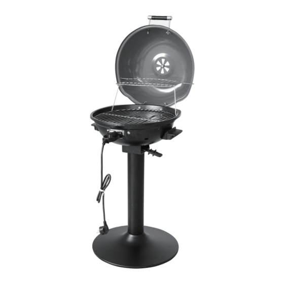
- Page 2 Electric Barbecue Grill Parts 1) IMPORTANT: Your Electric Barbecue Grill has been shipped with the components shown below. Check everything carefully before assembly or use. If any part is missing or damaged, do not use this product and contact the after-sales service center. 2) PRODUCT DIAGRAM 1.
- Page 3 3) SCREWS AND WASHER COMPONENTS 17. Small Screw M5X12 (7 pcs) 18. Medium Screw M6X20 (13 pcs) 19. Long Screw M6X45 (4 pcs) 20. Small Wing Nut M5 (6 pcs) 21. Large Wing Nut M6 (11 pcs) 22. Lock Washer (27 pcs) 23.
- Page 4 Assembly Instructions NOTE: Tighten all connections by hand first. Once assembly is complete, tighten all connections fully. Step 1 – Attach Pillar to Base Hardware: M6X20 Medium Screw – 4pcs Lock Washer – 4pcs Flat Washer – 4pcs Unscrew and put aside the four (4) M6X20 medium screws on one end of the pillar.
-
Page 5: Step 2 - Connection Part
Step 2 - Connection Part Hardware: M6X20 Medium Screw – 4pcs Lock Washer – 4pcs Flat Washer – 4pcs Unscrew and put aside the four (4) medium screws M6X20 on the other end of the pillar. Align the pillar to the bottom of the connection part, then screw the pillar to the bottom of the connection part using the four (4) M6X20 screws previously removed. - Page 6 Step 3 – Attach the Bowl Hardware: M6X20 Medium Screw – 5pcs M6 Large Wing Nut – 5pcs Lock Washer – 5pcs Flat Washer – 5pcs Place the assembled base on flat ground. Unscrew and put aside the five (5) large wing nuts M6 on the top connection part. Place the bowl on the top of the connection part and affix the bowl to the connection part using the five (5) M6 medium wing nuts previously removed.
- Page 7 Step 4 - Bowl Handles Hardware: M6 Large Wing Nut – 4pcs Lock Washer – 4pcs Flat Washer – 4pcs Long Screw M6 x 45-4pcs Unscrew the two (2) M6 large wing nuts from each of the two (2) handles with four long screws M6 x 45 and put aside. Affix the two (2) handles to either side of the bowl by using the M6 large wing nuts previously removed.
- Page 8 Step 5 – Bowl Hinge Bracket Hardware: M5X12 Small Screw – 2pcs Flange Nut – 2pcs Lock Washer – 2pcs Flat Washer – 2pcs Unscrew the two(2) Flange nuts M5 from the the hinge bracket and put aside. Use two(2) M5X12 small screws and put them through the holes in the bowl.
- Page 9 Step 6 – Lid Hinge Bracket Hardware: M5X12 Small Screw – 2pcs M5 Small Wing Nut – 2pcs Lock Washer – 2pcs Flat Washer – 2pcs Unscrew the small wing nut on the hinge bracket. Affix the hinge bracket to the lid using the small wing nut previously removed. Flat Washer (2 pcs) Lock Washer (2 pcs) Small Screw M5x12 (2 pcs)
- Page 10 Step 7 – Locking Pin Hardware: Locking Pin M5*123 – 1pc M5 Small Wing Nut – 1pc Lock Washer – 1pc Flat Washer – 1pc Affix the hinge bracket on the bowl to the hinge bracket on the lid using the locking pin. Lock them using the M5 small wing nut. M5 Small Wing Nut (1 pc) Lock Washer (1 pc) Flat Washer (1 pc)
-
Page 11: Step 8 - Air Vent
Step 8 – Air Vent Hardware: M5X12 Small Screw – 1pc M5 Small Wing Nut – 1pc Lock Washer – 1pc Flat Washer – 1pc Affix the air vent in the middle of the lid. Step 8 Flat Washer (1 pc) Lock Washer (1 pc) Small Wing Nut M5 (1 pc) -
Page 12: Step 9 - Lid Handle
Step 9 – Lid Handle Hardware: M6 Large Wing Nut – 2pcs Lock Washer – 2pcs Flat Washer – 2pcs Affix the lid handle to the lid using two (2) M6 large wing nuts. Flat Washer (2 pcs) Lock Washer (2 pcs) Large Wing Nut M6 (2 pcs) Step 9... -
Page 13: Step 10 - Heating Components
Step 10 – Heating Components Hardware: M5X12 Small Screw – 2pcs M5 Small Wing Nut – 2pcs Lock Washer – 2pcs Flat Washer – 2pcs Place the heat reflector plate in the bowl, then place the heating element in the bowl. Affix using M5X12 small screw and then lock using M5 nut. -
Page 14: Step 11 - Cooking Grill
Step 11 – Cooking Grill Place the cooking grill in the bowl. Step 11... - Page 15 Step 12 – Warming Rack and Oil Pan Insert the Foldable Warming Rack upper layer into the related side holes of the lid, insert the lower layer into the related side holes of the bowl. Place the Oil pan into the Connection part (part 11) . Step 12 Figure 1...
-
Page 16: Using The Temperature Control
Using the Temperature Control Powering Up the Barbecue 1. Make sure the temperature control knob is fully turned to the “OFF” position.( Fig.1 part 7) 2. Plug the temperature controller fully into the heating element front mounting bracket. (Fig. 2,). With the temperature dial facing upwards, the controller probe (and power connection holes) should be inserted until the controller front wall is snug against the heating element front mounting bracket. - Page 17 3. Plug the other end of the temperature control knob into a dry ground-fault circuit-interrupter (GFCI) power outlet. WARNING: DO NOT use an extension cord. ( see IMPORTANT SAFEGUARD again ) 4. Then adjust the setting on the control knob to the desired temperature level.
- Page 18 Pièces de Gril de Barbecue Électrique 1) IMPORTANT : Votre barbecue électrique a été expédié avec les composants illustrés ci-dessous. Vérifiez tout soigneusement avant le montage ou l'utilisation. Si une pièce est manquante ou endommagée, n'utilisez pas ce produit et contactez le centre de service après-vente.
- Page 19 3) VIS ET COMPOSANTS DE RONDELLE 17.Petite vis M5X12 (7 pièces) 18. Vis moyenne M6X20 (13 pièces) 19. Vis longue M6X45 (4 pièces) 20. Petit écrou papillon M5 (6 pièces) 21. Grand écrou papillon M6 (11 pièces) 22. Rondelle de blocage (27 pièces) 23.
-
Page 20: Instructions De Montage
Instructions de Montage REMARQUE : Serrez d'abord toutes les connexions à la main. Une fois l'assemblage terminé, serrez complètement toutes les connexions. Étape 1 - Fixez le pilier à la base Accessoire : Vis moyennes M6X20 - 4 pièces Rondelle de blocage – 4 pièces Rondelle plate –... - Page 21 Étape 2 - Pièce de connexion Accessoire : vis moyennes M6X20 - 4 pièces Rondelle de blocage – 4 pièces Rondelle plate – 4 pièces Dévisser et mettre de côté les quatre (4) vis moyennes M6X20 à l'autre extrémité du pilier. Aligner le pilier au bas de la pièce de connexion, puis visser le pilier au bas de la pièce de connexion à...
- Page 22 Étape 3 - Fixez le bol Accessoire : Vis moyennes M6X20 - 5 pièces Grands écrous papillon M6 - 5pcs Rondelle de blocage – 5 pièces Rondelle plate – 5 pièces Placez la base assemblée sur un sol plat. Dévisser et mettre de côté les cinq (5) gros écrous papillon M6 sur la pièce de connexion supérieure.
- Page 23 Étape 4 - Poignées du bol Accessoire : Grands écrous papillon M6 – 4 pièces Rondelle de blocage – 4 pièces Rondelle plate – 4 pièces Vis longue M6 x 45-4pcs Dévissez les deux (2) grands écrous papillon M6 de chacune des deux (2) poignées avec quatre vis longues M6 x 45 et mettez-les de côté.
- Page 24 Étape 5 - Support de charnière de bol Accessoire : Petites vis M5X12 – 2 pièces Écrous à embase – 2 pièces Rondelle de blocage - 2 pièces Rondelle plate – 2 pièces Dévissez les deux (2) écrous à bride M5 du support de charnière et mettez-les de côté.
- Page 25 Étape 6 - Support de charnière de couvercle Accessoire : Petites vis M5X12 – 2 pièces Petits écrous papillon M5 - 2 pièces Rondelle de blocage - 2 pièces Rondelle plate – 2 pièces Dévissez le petit écrou papillon sur le support de charnière. Fixez le support de charnière au couvercle à...
- Page 26 Étape 7 - Goupille de verrouillage Accessoire : Goupille de verrouillage M5*123 – 1pc Petit écrou papillon M5 - 1pc Rondelle de blocage - 1pc Rondelle plate - 1pc Fixez le support de charnière du bol au support de charnière du couvercle à...
- Page 27 Étape 8 - Évent d'aération Accessoire : Petite vis M5X12 – 1pc Petit écrou papillon M5 - 1pc Rondelle de blocage - 1pc Rondelle plate - 1pc Fixez l’évent d'aération au milieu du couvercle. Étape 8 Rondelle plate (1 pc) Rondelle de blocage (1 pc) Petit écrou papillon M5 (1 pc)
-
Page 28: Étape 9 - Poignée Du Couvercle
Étape 9 - Poignée du couvercle Accessoire : Grand écrou papillon M6 – 2 pcs Rondelle de blocage - 2 pcs Rondelle plate – 2 pcs Fixez la poignée du couvercle au couvercle à l'aide de deux (2) grand écrou papillon M6. Rondelle plate (2 pcs) Rondelle de blocage (2 pcs) - Page 29 Étape 10 - Composants chauffants Accessoire : Petites vis M5X12 – 2 pcs Petit écrou papillon M5 - 2pcs Rondelle de blocage - 2 pcs Rondelle plate – 2 pcs Placez la plaque réflectrice de chaleur dans le bol, puis placez l'élément chauffant dans le bol.
- Page 30 Étape 11 - Grille de cuisson Placez la grille de cuisson dans le bol. Étape 11...
- Page 31 Étape 12 - Grille de réchaud et bac à huile Insérez la couche supérieure de la grille chauffante pliable dans les trous latéraux correspondants du couvercle, insérez la couche inférieure dans les trous latéraux correspondants du bol. Placez le carter d'huile dans la pièce de connexion (pièce 11) . Étape 12 Figure 1...
- Page 32 Utilisation du Contrôle de la Température Allumer le barbecue 1. Assurez-vous que le bouton de contrôle de la température est complètement tourné sur la position «OFF». (Fig.1 partie 7) 2. Branchez complètement le contrôleur de température dans le support de montage avant de l'élément chauffant. (Fig. 2,). Avec le cadran de température orienté...
- Page 33 3. Branchez l'autre extrémité du bouton de contrôle de la température dans une prise de courant à disjoncteur de fuite à la terre (GFCI). AVERTISSEMENT : N'UTILISEZ PAS de rallonge. (voir à nouveau GARANTIE IMPORTANTE) 4. Ajustez ensuite le réglage du bouton de commande au niveau de température souhaité.
- Page 34 With your inspiring rating, COSTWAY will be more consistent to offer you EASY SHOPPING EXPERIENCE, GOOD PRODUCTS and EFFICIENT SERVICE! Mit Ihrer inspirierenden Bewertung wird COSTWAY konsistenter sein, um Ihnen EIN SCHÖNES EINKAUFSERLEBNIS, GUTE PRODUKTE und EFFIZIENTEN SERVICE zu bieten! Avec votre évaluation inspirante, COSTWAY continuera à...
Need help?
Do you have a question about the EP24757US and is the answer not in the manual?
Questions and answers