Table of Contents
Advertisement
Quick Links
Please give us a chance to make it right and do better !
Contact our friendly customer service department for help first.
Replacements for missing or damaged parts will be shipped ASAP !
US office: Fontana
UK office: Ipswich
DE office: Hamburg
FR office: Saint Vigor d'Ymonville
Contact Us!
Do NOT return this item.
AU office: Truganina
PL office: Gdańsk
US:cs.us@costway.com
UK:cs.uk@costway.com
AU:cs.au@costway.com
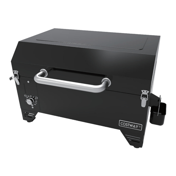
Portable Pellet Grill
THIS INSTRUCTION BOOKLET CONTAINS IMPORTANT SAFETY INFORMATION. PLEASE READ AND KEEP FOR FUTURE REFERENCE.
USER'S MANUAL
FP10073US
Advertisement
Table of Contents

Subscribe to Our Youtube Channel
Related Manuals for Costway FP10073US


Summary of Contents for Costway FP10073US
- Page 1 DE office: Hamburg FR office: Saint Vigor d'Ymonville PL office: Gdańsk USER’S MANUAL Contact Us! Portable Pellet Grill FP10073US US:cs.us@costway.com Do NOT return this item. UK:cs.uk@costway.com AU:cs.au@costway.com THIS INSTRUCTION BOOKLET CONTAINS IMPORTANT SAFETY INFORMATION. PLEASE READ AND KEEP FOR FUTURE REFERENCE.
-
Page 2: Safety Information
SAFETY INFORMATION MAJOR CAUSES OF APPLIANCE FIRES ARE A RESULT OF POOR MAINTENANCE AND A FAILURE TO MAINTAIN REQUIRED CLEARANCE TO COMBUSTIBLE MATERIALS. IT IS OF UTMOST IMPORTANCE THAT THIS PRODUCT SHOULD BE USED ONLY IN ACCORDANCE TO THE FOLLOWING INSTRUCTIONS Please read and understand this entire manual before attempting to assemble, operate or install the product. -
Page 3: Wood Pellet Fuel
WOOD PELLET FUEL After a period of storage, or non-use, check the burn grate for obstructions, the hopper for foreign objects, and any air blockage around This pellet cooking appliance is designed and approved for pelletized, all the fan intake, chimney, or rear barrel exhaust holes. Clean before use. natural, wood fuel only. -
Page 4: Carbon Monoxide
CARBON MONOXIDE PARTS & SPECS Carbon monoxide is a colorless, odorless, tasteless gas produced by burning gas, wood, propane, charcoal or other fuel. Carbon monoxide reduces the Part# Description blood’s ability to carry oxygen. Low blood oxygen levels can result in Upper Cooking Rack (x1) headaches, dizziness, weakness, nausea, vomiting, sleepiness, confusion, loss of consciousness or death. -
Page 5: Assembly Preparation
MODEL COOKING AREA WEIGHT (WxHxD) 619mm*368mm Main - 1,235 cm /191 sq. in. 18.7KG Parts Required: FP10073US *460mm/24.3”* Upper Rack - 417 cm /65 sq. in. /41.1LBS Main Barrel 14.5”*18.1” TOTAL - 1,652 cm /256 sq. in. / Hopper Assembly(#7) Foot Assembly(#10) TEMP. -
Page 6: Installing The Cooking Components
3. INSTALLING THE COOKING COMPONENTS 4. CONNECTING THE POWER CORD Parts Required: Parts Required: Flame Broiler Main Plate (#4) Main Barrel/Hopper Assembly (#7) Flame Broiler Slider (#3) Power Cord (#8) Installation: Installation: • Insert the flame broiler main plate • Insert the end of the power cord into the main grill, right side first. -
Page 7: Grill Environment
OPERATING INSTRUCTIONS 6. CONNECTING THE POWER CORD With today’s lifestyle of striving to eat healthy and nutritious foods, one factor NOTE: Before plugging your product into any electrical outlet, ensure the to consider is the importance of reducing fat intake. One of the best ways to temperature dial is in the OFF position. -
Page 8: Grill Temperature Ranges
• • MEDIUM TEMPERATURE (135-180°C / 275-356°F) Avoid lifting the lid any more than necessary. Cold gusts of wind can completely cool your grill temperature. Be flexible with your serving time; This range is best for baking, roasting, and finishing off that slow smoked add extra cooking time each time you open the lid. -
Page 9: Understanding The Control Board
UNDERSTANDING THE CONTROL BOARD FEATURE DESCRIPTION The LCD Screenis used as the information center for your unit. The LCD screen will display the current grill temperature (ACTUAL) and meat probe temperature (MP1). SeeTroubleshooting for more information on error codes. READOUT DESCRIPTION Flashing Indicates the unit was just connected to AC power. -
Page 10: First Use - Grill Burn-Off
• That you can hear the auger turning. Place your hand above the fire pot TheTemperature Control Dial allows you to set your desired and feel for air movement. Do not place your hand or fingers inside the temperature. Rotate the knob marker to select from Smoke, fire pot. -
Page 11: Manual Start-Up Procedure
IGNITER FAILURE PROCEDURE CARE AND MAINTENANCE If for any reason your electric igniter fails or your grill's flame dies out during a cook, check the following steps, or start your grill using the manual method. The product will give you many years of flavorful service with minimum cleaning. -
Page 12: Outside Surfaces
4. OUTSIDE SURFACES LAMB Size Rare-54°C Medium- Well Done- • Wipe your grill down after each use. Use warm soapy water to cut the /130°F 60°C /140°F 71°C /160°F grease. Do not use oven cleaner, abrasive cleansers or abrasive cleaning pads on the outside grill surfaces. -
Page 13: Grilling Tips And Techniques
• A marinade should never be saved to use at a later time. If you are going HOW TO USE MEAT PROBE to use it to serve with your meat, be sure to bring it to a boil before serving. •... -
Page 14: Troubleshooting
TROUBLESHOOTING PROBLEM CAUSE SOLUTION Fire in Fire Auger Motor Remove cooking components from the main barrel. Proper cleaning, maintenance and the use of clean, dry, quality fuel will pot Will Not Is Jammed Press the Power Button to turn the unit on, turn prevent common operational problems. - Page 15 PROBLEM CAUSE SOLUTION PROBLEM CAUSE SOLUTION Grill Will Not Insufficient Check fire pot for ash build-up or obstructions. "ErH" Error The Unit Has Press the Power Button to turn the unit off, and Achieve Or Air Flow Follow Care and Maintenance instructions for ash Code Overheated, allow grill to cool.
-
Page 16: Replacement Parts
REPLACEMENT PARTS Part# Description Lid (x1) 18-A Grease Tray Assembly (x1) Lid Hinge (x2) Service Door (x1) 19-A Hasp (x2) 20-A Control Board (x1) Bezel With bolt (x2) 21-A Logo Plate (x1) Lid Handle (x1) 22-A Auger Motor (x1) Hopper Lid Hinge (x2) 23-A Combustion Fan (x1) Hopper Lid (x1) -
Page 17: Electrical Wire Diagram
ELECTRICAL WIRE DIAGRAM The Digital Control Board system is an intricate and valuable piece of technology. For protection from power surges and electrical shorts, consult the wire diagram below to ensure your power source is sufficient for the operation of the unit. ELECTRIC REQUIREMENTS 110-120V, 60Hz, 230W, 3-PRONG GROUNDED PLUG...
Need help?
Do you have a question about the FP10073US and is the answer not in the manual?
Questions and answers