Advertisement
Quick Links
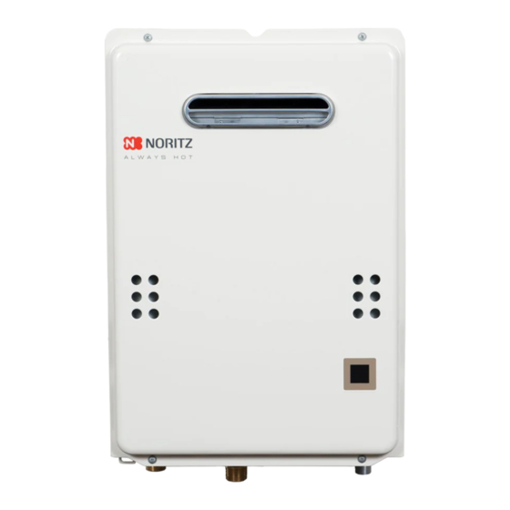
Model Include:
This instructional manual is only intended for use by a qualified service professional or authorized Noritz
Service Representative. Any unauthorized use of this manual may result in voiding the warranty.
Please contact Noritz Technical Support (866-766-7489) for additional support.
SKJ70NL
Rev. 10/13
NR501, NR662 Series Heat Exchanger
Replacement
NR501-OD, NR662-OD
Noritz America Corporation
11160 Grace Avenue, Fountain Valley, CA 92708
Phone 866-766-7489 Fax 714-241-1196
Page 1
Advertisement


Need help?
Do you have a question about the NR501 Series and is the answer not in the manual?
Questions and answers