Noritz NR66-SV Installation Manual
Hide thumbs
Also See for NR66-SV:
- Service manual (96 pages) ,
- Installation manual (64 pages) ,
- Owner's manual (32 pages)
Table of Contents
Advertisement
Quick Links
Installation Manual
TANKLESS GAS WATER HEATER
NR71-SV, NR66-SV
NR71-OD, NR66-OD
NR50-OD
Potential dangers from accidents during installation and use are divided into the following three
categories. Closely observe these warnings, they are critical to your safety.
DANGER
WARNING
CAUTION
WARNING:
If the information in this manual is not followed exactly, a fire or explosion may result
causing property damage, personal injury or death.
Prohibited
Requests to Installers
• In order to use the water heater safely, read this installation manual carefully, and follow the in-
stallation instructions.
• Failures and damage caused by erroneous work or work not as instructed in this manual are not
covered by the warranty.
• Check that the installation was done properly in accordance with this Installation Manual upon
completion.
• After completing installation, please either place this Installation Manual in a plastic pouch and
attach it to the side of the water heater (or the inside of the pipe cover or recess box if applicable),
or hand it to the customer to retain for future reference. Also, be sure to fill in all of the required
items on the warranty and to hand the warranty to the customer along with the Owner's Guide.
CERTIFIED
R
SBA8655
Rev. 12/10
(Indoor/Outdoor Installation, For USA and Canada)
(Outdoor Installation, For USA and Canada)
(Outdoor Installation, For USA only)
DANGER indicates an imminently hazardous situation which,
if not avoided, will result in death or serious injury.
WARNING indicates a potentially hazardous situation which,
if not avoided, could result in death or serious injury.
CAUTION indicates a potentially hazardous situation which,
if not avoided, may result in minor or moderate injury.
Disconnect
Power
CAUTION
FOR USE IN RESIDENTIAL, COMMERCIAL, OR MANUFACTURED HOME
APPLICATIONS. (-OD type only)
Installation must conform with local codes, or in the absence of local codes,
the National Fuel Gas Code, ANSI Z223.1/NFPA 54- latest edition and/or
CSA B149.1, Natural Gas and Propane Installation Code (NSCNGPIC).
When applicable, installation must conform with the Manufactured Home
Construction and Safety Standard, Title 24 CFR, Part 3280 or the Cana-
dian Standard CAN/CSA-Z240 MH Mobile Homes, Series M86. (NR66-OD,
NR71-OD only)
Noritz America reserves the right to discontinue, or change at any time, the
designs and/or specifications of its products without notice.
Ground
NORITZ AMERICA
CORPORATION
Be sure to do
*SBA8655*
Advertisement
Table of Contents

Related Manuals for Noritz NR66-SV


Summary of Contents for Noritz NR66-SV
- Page 1 Construction and Safety Standard, Title 24 CFR, Part 3280 or the Cana- dian Standard CAN/CSA-Z240 MH Mobile Homes, Series M86. (NR66-OD, CERTIFIED NR71-OD only) Noritz America reserves the right to discontinue, or change at any time, the designs and/or specifications of its products without notice. SBA8655 Rev. 12/10...
-
Page 2: Included Accessories
Shape Q’ty Remote Controller* Remote Controller Cord (10ft) (See p. 22) Outdoor Vent Cap Remote Controller VC4-1 (NR71-SV only) Cord (26ft) VC3 (NR66-SV only) Isolation Valves Recess Box (includes pressure relief valve) RB-600 (NR71-OD only) RB-500 (NR66-OD, NR50-OD only) Pipe Cover (PC-1S) -
Page 3: Before Installation
Before Installation DANGER Checkup • Check the fixing brackets and vent pipe yearly for damage or wear. Replace if necessary. WARNING Check the Gas Ex. For Natural Gas NR71-SV • Check that the rating plate indicates the NR71-SV correct type of gas. 180,000 BTU 25,000 BTU •... -
Page 4: Choosing Installation Site
Choosing Installation Site * Locate the appliance in an area where leakage from the unit or connections will not result in damage to the area adjacent to the appliance or to the lower floors of the structure. When such locations can- not be avoided, it is recommended that a suitable drain pan, adequately drained, be installed under the appliance. - Page 5 1) The outdoor units (-OD type only) can only be used if they are for summer use only. 2) The water heater can be used for hot water only and not in a combination of domestic and space heating. For Venting Manufacturers Requirements, see websites or phone numbers listed below: Noritz N-Vent www.noritz.com...
-
Page 6: Installation Clearances
Installation Clearances WARNING Before installing, check for the following: Install in accordance with relevant building and mechanical codes, as well as any local, state or national regulations, or in the absence of local and state codes, to the National Fuel Gas Code ANSI Z223.1/NFPA 54 –... - Page 7 [ -OD type only ] Illustration Item Check • Maintain the following clearance from both combustible and non-combustible materials. 24" (12") * ( ) indicates the distance when installing a heat insu- or more lating board (incombustible material other than metal, with thickness of 0.1"...
- Page 8 Clearance Requirements from Vent Terminations to Building Openings * All clearance requirements are in accordance with ANSI Z21.10.3 and the National Fuel Gas Code, ANSI Z223.1 and in Canada, in accordance with NSCNGPIC. Vent Terminal Area Where Terminal is Not Permitted Air Supply Inlet Indoor Installation Outdoor Installation...
- Page 9 3' above any forced air inlet within 10'. Noritz vent cap VC4-1 (NR71-SV only) (NR66-SV only) * For Installations in Canada, clearances are as follows: To windows, doors, & gravity air inlets: 36".
- Page 10 [ -OD type only ] Maintain the following clearances to any Illustration opening in any building: • 1' below, 1' horizontally from, or 1' above any door, operable window, or gravity air inlet into any building. 3' above any forced air inlet within 10'. •...
-
Page 11: Installation
Installation Securing to the wall • The weight of the device will be applied to the wall. If the strength of the wall is not suffi- cient, reinforcement must be done to prevent the transfer of vibration. • Do not drop or apply unnecessary force to the device when installing. Internal parts may be damaged and may become highly dangerous. -
Page 12: Vent Pipe Installation
• The first vertical run from the top of the heat- er should be no longer than 3'. • Noritz N-Vent is suggested for the vent system. • Make sure vent pipe is gas tight and will not If N-Vent is not used, a UL listed category III leak. - Page 13 Adapter* ity air inlet into any building per National Fuel Gas Code ANSI Z223.1/NFPA 54. * Adapter not required when using Noritz N-Vent. • Slope the horizontal vent 1/4" downwards **1' minimum recommended, for every 12" toward the termination. but not required. Avoid installing elbow directly on flue.
-
Page 14: Combustion Air
Supply combustion air to the units as per the National Fuel Gas Code, ANSI Z223.1 Combustion Air and in Canada, in accordance with NSCNGPIC. • Provide two permanent openings to allow cir- culation of combustion air. 9" • Make each opening 180 square inches if they 20"... -
Page 15: Gas Piping
NPT screw with an allen wrench and connecting the appropriate pressure gauge. Sample Gas Line Instructions Noritz Gas Water Heater (NR71 series:180,000 Btuh) 1. Size each outlet branch starting from the furthest (NR66 series:140,000 Btuh) using the Btuh required and the length from the... - Page 16 Gas Line Sizing for a Noritz Gas Water Heater Adapted from UPC 1997 Maximum Natural Gas Delivery Capacity in Cubic Feet per Hour (0.60 Specific Gravity, 0.5" WC Pressure Drop) Length in Feet Pipe Size 100' 125' 1/2" 3/4" 1"...
-
Page 17: Water Piping
Installation and service must be performed by a qualified plumber. In the Water Piping Commonwealth of Massachusetts, this product must be installed by a licensed plumber or gas fitter in accordance with the Massachusetts Plumbing and Fuel Gas Code 248 CMR Sections 2.00 and 5.00. Observe all applicable codes. This appliance is suitable for potable water and space heating applications. - Page 18 Supply water piping Hot water piping • Do not use PVC, iron, or any piping which has been • Do not use lead, PVC, iron or any piping which treated with chromates, boiler seal or other chemicals. has been treated with chromates, boiler seal or •...
-
Page 19: Water Treatment System
If this water heater will be installed in an application where the supply water is hard, the water must be treated with either the Noritz H2Flow or ScaleShield or a water softener. Refer to the below tables for suggested treatment and maintenance measures to be taken based on the water hardness level. Dam- age to the water heater as a result of water in excess of 12 gpg (200 mg/L) of hardness is not covered by the Noritz America Limited Warranty. -
Page 20: Plumbing Applications
(Model L6006A or L6006C) Combination Potable Water and Space Heating System Notes: 1. Noritz recommends the use of an Isolation Kit with the installation. These kits include an integrated shut-off and serv- ice valve with unions and a pressure relief valve. -
Page 21: Electrical Wiring
Electrical Wiring Consult a qualified electrician for the electrical work. Do not connect electrical power to the unit until all electrical wiring has been completed. Disconnect Power This appliance must be electrically grounded in accordance with local codes, or in the absence of local codes, with the National Electrical Code, ANSI/NFPA 70. -
Page 22: Remote Controller
Remote Controller • Applicable Model RC-7649M Remote controller Install the remote controller according to the instructions in the Installation Guide (p. 29). • The water heater can be programmed so that it will default to one of three temperatures (140, 135, 130°F) when the temperature selection wire is connected. - Page 23 Connecting Remote Controller Cord to Unit • Keep the remote controller cord away from the freeze prevention heaters in the unit. • Tie the redundant cord outside the water heater. Do not put the extra length inside the equipment. • The remote controller cord can be extended up to 83' with 18AWG wire. •...
-
Page 24: Maintenance
Maintenance Periodically check the following to ensure proper operation of the water heater. • The venting system must be examined periodically by a qualified service technician to check for any leaks or corrosion. • The burner flame must be checked periodically for a proper blue color and consistency. •... -
Page 25: Lighting Instructions
WARNING A fire or explosion may result if these instructions are not followed, which may cause lose of life, personal injury or property damage. Lighting Instructions This water heater does not have a pilot. It is equipped with an ignition device that automatically lights the burner. - Page 26 Dimensions NR71-SV 13.3" (VIEW FROM TOP) 4- 0.5" 10.5" 7.8" 2-0.3" x 0.5" 0.4" 6.7" 13.8" 6.2" OBLONG HOLE 3" 13.1" 1.4" 4.7" 4" 1.1" FLUE COLLAR HOT WATER OUTLET(3/4") 2.0" GAS INLET (3/4") COLD WATER INLET(3/4") 3.3" WIRING THROUGHWAYS 1.7"...
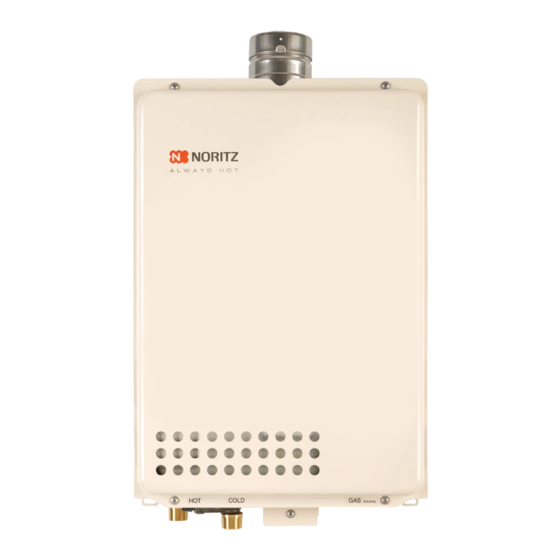
- Page 27 NR66-SV (VIEW FROM TOP) 10.0" 7.0" 4.3" 1.5" 13.3" HOT WATER OUTLET(3/4") GAS INLET (3/4") COLD WATER INLET(3/4") 7.2" WIRING THROUGHWAYS 13.8" 0.4" 6.7" 13.1" 4.7" 3" 3.0" FLUE COLLAR UPPER WALL MOUNT BRACKETS 4.7" AIR INLET 2.4" BOTTOM OF CASE...
- Page 28 NR50-OD (VIEW FROM TOP) 10.0" 7.0" 4.3" 13.3" 1.5" HOT WATER OUTLET(3/4") GAS INLET (1/2") COLD WATER INLET(3/4") 7.2" WIRING THROUGHWAYS 13.8" 4.7" 0.4" 6.7" 13.1" FLUE TERMINAL UPPER WALL MOUNT BRACKETS 4.7" AIR INLET 2.4" BOTTOM OF CASE BOTTOM OF CASE AIR INLET 0.4"...
-
Page 29: For Installers
Remote Controller RC-7649M carefully before carrying out installation. Installation Guide NORITZ AMERICA CORPORATION Note Do not connect power to the water heater before the remote controller has been properly installed. Recommended installation location of the remote controller is in a bathroom. - Page 30 Installation 3. Remove the cover of the remote control, 1. Apply Wall Packing to the rear side of the mark the location of the screw holes, and remote controller. drill holes for the wall anchors. 2. Connect the remote controller wires to the 4.
- Page 31 Installing the Remote Controller Outdoor Junction Box 5. Slide the box nut over the remote controller 1. Insert the remote controller wires through the wires and screw it onto the wall pipe. wall pipe and secure the wall pipe to the re- mote controller.
Need help?
Do you have a question about the NR66-SV and is the answer not in the manual?
Questions and answers