Advertisement
Quick Links
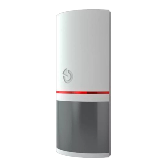
JA-151P-WG Wireless PIR motion detector
The JA-151P-WG is a wireless component of the JABLOTRON 100
system. It serves for the detection of human movement in building
interiors. Its guaranteed detection coverage is 90° horizontally
and detection range is 12 m. This PIR motion detector utilizes a grey
lens which provides better immunity against white light well above
values required by the norm (up to 10000 lux).This helps to reduce
false alarms caused by car lights, sunsets, lightning or reflective
surfaces. False alarm immunity is available in two options. The detector
has a pulse reaction and takes one position in the system. The detector
should be installed by a trained technician with a valid certificate issued
by an authorized distributor.
Installation
It's necessary to take into consideration that there should be no
obstacles in the detector's view which quickly change temperature (electric
heaters, gas appliances, etc.), which move (e.g. curtains hanging above
a radiator, robotic vacuum cleaners) or the movement of house pets.
Despite the detector being very immune to false alarms, it is not
recommended to install the detector opposite windows or floodlights or in
places with over-intense air circulation (close to ventilators, heat sources,
air conditioning outlets, unsealed doors, etc.). There should be no
obstacles in front of the detector obscuring its view over the guarded
space.
Figure 1: 1 – LED indicators, 2 – PIR lens, 3 – Hole for locking screw,
4 – Cover tab
1. Open the detector cover by pressing the cover tab (4). Avoid
touching the PIR sensor inside (6) – you could damage it
2. Take out the PCB – it is held by a tab in the lower part.
3. Punch through the holes for the screws and the cable in the plastic
base. The recommended installation height is 2.5 m above
the floor.
4. Set the DIP switches (9) according to the requirements, see
the Detector settings.
5. Insert the PCB back and proceed according to the control panel
installation manual. Basic procedure:
a. The control panel must contain the JA-110R radio module.
b. Go to the F-Link software, select the required position in
the Devices window and launch the Enrollment mode by
clicking on the Enroll option.
c. Insert the batteries (mind the correct polarity). When the second
battery has been inserted into the detector, an enrollment signal
is transmitted to the control panel and the detector is enrolled to
the selected position. The detector can be enrolled by entering
the production code (8).
d. This is followed by a detector stabilization phase indicated with
LED indicator (10) flashing which takes up to three minutes.
6. Close the detector cover.
Figure 2: 5 – Antenna; 6 – PIR sensor; 7 – Tamper contact; 8 – Production
code; 9 – Setting DIP switches; 10 – Red LED indicator;
11 – The JA-191PL external tamper connector; 12 – Battery holder
Note:
The detector can be removed from the system by deleting it from
its position in the Devices tab.
JA-151P-WG Wireless PIR motion detector
Detector internal settings
Internal settings can be configured by DIP switch on a PCB inside
the detector (*factory defaults).
Immunity level: DIP switch no. 1 determines a level of false alarm
immunity. The NORM* level (default setting) combines basic immunity
with a rapid reaction. The HIGH level (DIP switch ON) provides
increased immunity but the detector reaction is slower.
External tamper sensor: DIP switch no. 2 can enable (DIP switch
ON) /disable* the external tamper of the JA-191PL jointed bracket.
Detector function modes
The detector can work in two modes. They are indicated by one or two
flashes of the LED light (10) when batteries are inserted.
One flash represents Smartwatch* mode. It's determined for
the permanent monitoring of movement in the guarded area.
If permanent movement is detected, three reports are sent every 20 s.
The next report is then sent after 2 minutes. If the detector does not
detect any movement for 10 minutes, the mode with three reports every
20 s is used again.
Two flashes represent a One minute interval. The detector enters
standby mode for 1 minute after it has detected movement. When
the standby mode times out, the detector wakes up and is ready to be
triggered again.
To change the mode, press and hold the tamper contact (7) in
the cover, insert the batteries at the same time. Release the tamper
contact 3-5 seconds after the batteries insertion. The detector then
flashes either once or twice to indicate the currently selected mode.
When batteries are replaced the setting doesn't change.
Detector testing
When you close the detector cover, LED light indicates all movement
for a period of 15 minutes and reports it to the control panel. After this
time the detector switches to the mode which was selected during
the battery insertion.
Detector functions can also be checked via the Diagnostics window
in the F-Link software. You can check the selected mode and immunity
level in Internal settings. This information serves as a preview and can't
be changed by F-link software.
Battery replacement
The system sends automatic reports when the battery is low.
Remember to switch the system to Service mode before changing
the batteries. It's necessary to wait for 10 seconds or repeatedly press
the tamper contact (7) in order to release the remaining charge before
you insert new batteries. If you insert batteries with low energy (
detected) the LED light will indicate that by flashing rapidly during
the testing period.
Detection characteristics
The standard lens that is supplied with the detector has a grey
colour and covers an area of 90° / 12 m. The area is covered by 3
beams (curtains) – see the following figure. The lens cannot be
replaced by a different type of lens.
Figure 3. This detection characteristic is valid for standard PIR immunity.
Installation accessories
JA-193PL – Detector wall holder. Instead of installing the detector
in a room's corner, it's possible to install it on a wall surface using
a JA-193PL aesthetic frame which is distributed in two colours – white
and grey. Using the frame, the detector is partially hidden under
a plaster or plasterboard wall.
JA-191PL – PIR jointed bracket. It is used for special placement,
such as installation on the ceiling or at a tilted angle (higher installation
height). The jointed bracket is a certified detector accessory having its
own tamper contact which is to be connected to the connector inside
the detector (11).
1 / 2
MMO51305
Advertisement

Related Manuals for jablotron JA-151P-WG


Summary of Contents for jablotron JA-151P-WG
- Page 1 JA-151P-WG Wireless PIR motion detector The JA-151P-WG is a wireless component of the JABLOTRON 100 Detector internal settings system. It serves for the detection of human movement in building interiors. Its guaranteed detection coverage is 90° horizontally Internal settings can be configured by DIP switch on a PCB inside and detection range is 12 m.
- Page 2 EN 50130-4, EN 55022 JABLOTRON ALARMS a.s. hereby declares that JA-151P-WG is in a compliance with the relevant Union harmonisation legislation: Directives 2014/53/EU, 2014/35/EU, 2014/30/EU, 2011/65/EU. The original of the conformity assessment can be found at www.jablotron.com - Section Downloads.
Need help?
Do you have a question about the JA-151P-WG and is the answer not in the manual?
Questions and answers