Advertisement
Quick Links
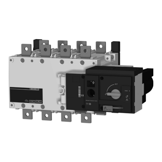
HIB4xxM
Preliminary operations
Check the following upon delivery and after removal of
the packaging:
• Packaging and contents are in good condition.
• The product reference corresponds to the order.
• Contents should include:
- 1 x motorised changeover switch
- 1 x emergency handle and fixing clip
- 1 x quick start instruction sheet
Accessories
• Bridging bars and connection kits
• Terminal shrouds
• Terminal shield
Installation and commissioning
Step 1
Step 2
Cabinet /
Back Plate
Installation
Clip for
storage
of the
emergency
handle
1
Motorised changeover switch
z
125A to 630A
This quick start is intended for personnel trained in the
installation and commissioning of this product. For further
details refer to the product instruction manual available
on the hager website.
• This product must always be installed and
commissioned by qualified and approved personnel.
• Maintenance and servicing operations should be
performed by trained and authorised personnel.
• Do not handle any control or power cables connected
to the product when voltage may be, or may become
present on the product, directly through the mains or
indirectly through external circuits.
• Always use an appropriate voltage detection device to
confirm the absence of voltage.
• Ensure that no metal objects are allowed to fall in the
cabinet (risk of electrical arcing).
Step 3
COMMAND /
Connecting the
CONTROL terminal
power section
connections
• For 125 - 160A (Uimp = 8 kV). Terminations must
respect a minimum of 8 mm clearance from live parts
to parts intended to be earthed and between poles.
• For 200 - 630A (Uimp = 12 kV). Terminations must
respect a minimum of 14 mm clearance from live parts
to parts intended to be earthed and between poles.
Failure to observe good enginering practises as well as
to follow these safety instructions may expose the user
and others to serious injury or death.
Step 4
Step 5
Power SUPPLY
Check
terminal
connections
Risk of electrocution, burns or injury to
persons
and / or
damage
to
equipment.
Risk of damaging the device: In case the
product is dropped or damaged in any way
it is recommended to replace the complete
product.
Step 6A
Control by
an external
order (AUTO)
Step 6B
Emergency
Manual
Operation
Step 6C
Padlocking
6LE007719Aa
Advertisement

Related Manuals for hager HIB4 M Series


Summary of Contents for hager HIB4 M Series
- Page 1 • For 200 - 630A (Uimp = 12 kV). Terminations must • Packaging and contents are in good condition.
- Page 2 1. Installation 4. Power supply terminal Remove the Top cover to access and connect the terminal - Replace the cover before putting in service. Door cut-out for front panel Dimensions in mm Ensure that the product is installed on a flat rigid surface. Clic ! 16,2 Max.
- Page 3 Notes Hager Electro S.A.S., Boulevard d'Europe, B.P. 3, 67215 OBERNAI CEDEX, France - www.hager.com Hager 07.21 OCOM 140890 6LE007719Aa...