
Subscribe to Our Youtube Channel
Related Manuals for SMA SMC 5000A


Summary of Contents for SMA SMC 5000A
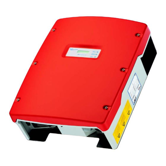
- Page 1 Sunny Mini Central SMC 5000A / 6000A Inverter for three-phase grid feeding PV plants Installation Guide Version 1.4 SMC50A_60A-11:SE3706 IME-SMC50A_60A...
-
Page 3: Table Of Contents
Technologie AG Table of Contents Table of Contents Notes on this manual ..... . 7 Validity ....... . . 7 Target group . - Page 4 Table of Contents Technologie AG 5.3.3 Reverse Current ........35 Connecting the AC output .
- Page 5 13.5.2 SMA grid guard certificate ......97 Glossary ......99 Contact.
- Page 6 Technologie AG Seite 6 SMC50A_60A-11:SE3706 Installation Guide...
-
Page 7: Notes On This Manual
1 Notes on this manual 1.1 Validity These installation instructions cover correct installation and commissioning of type Sun- ny Mini Central SMC 5000A and SMC 6000A SMA inverters. 1.2 Target group Only trained electricians approved by the responsible power supply company may in- stall and commission the inverters. - Page 8 Notes on this manual Technologie AG Page 8 SMC50A_60A-11:SE3706 Installation Guide...
-
Page 9: The Sunny Mini Central
Do not use the Sunny Mini Central for purposes other than those described here. Alternative uses, modifications to the inverter as well as installing components not recommended or sold by SMA void the warranty and operating permission. Principle of a solar system with a Sunny Mini Central... -
Page 10: Overview Of The Device
Technologie AG 2.2 Overview of the device The following diagram gives a schematic overview of the various components and con- nection points inside the SunnySunny Mini Central Mini Central SMC 5000A and SMC 6000A with the cover removed: Page 10... - Page 11 Technologie AG The Sunny Mini Central Varistors (page 70) Connection terminals for communication (page 51) Socket for communications Piggy-Back (RS232, RS485, Radio) (page 51) Jumper for communication (page 51) Sunny Display (page 56) Jumper for fan testing (page 75) Operating status LEDs (page 59) Connection terminals for mains cable (AC) (page 39) Cable duct for mains cable (AC) (page 39) Flat connection for grounding the cable shield for RS232 and RS485 commu-...
-
Page 12: Dimensions
The Sunny Mini Central Technologie AG 2.3 Dimensions 242 mm 468 mm 613 mm Page 12 SMC50A_60A-11:SE3706 Installation Guide... - Page 13 Technologie AG The Sunny Mini Central Wall mounting bracket and rear panel 2,6 2,6 11,0 43,3 Holes for wall mount Specifications in cm 48,7 Holes optional single-use screws as theft protection (4 x) Installation Guide SMC50A_60A-11:SE3706 Page 13...
-
Page 14: Identification
The type plate is found on the right-hand side of the enclosure (when viewed from the front). It contains information regarding the device type, serial number, device-spe- cific key data, the CE mark and SMA contact information. The following is an example of a Sunny Mini Central SMC 6000A type plate. -
Page 15: Special Features
Technologie AG The Sunny Mini Central 2.5 Special features: 2.5.1 LEDs The Sunny Mini Central is fitted with an operating status (Green) indicator, the three LEDs on the cover at the front, as standard. The are green, yellow and red and can indi- (Red) cate the operating status of the Sunny Mini Central via (Yellow) -
Page 16: Opticool
The Sunny Mini Central Technologie AG 2.5.3 OptiCool The Sunny Mini Central comes equipped with the patented Opti- Cool dual-chamber cooling system. At the same time, the inver- ter's enclosure is integrated into the temperature management and now serves not only to incorporate and protect the internal components but also as a cool air and heat distributor. -
Page 17: Electronic Solar Switch (Ess)
Technologie AG The Sunny Mini Central 2.5.4 Electronic Solar Switch (ESS) The Sunny Mini Central can be equipped with the "ESS" in- tegrated electronic DC circuit breaker, which fulfills all re- quirements for the installation standard for photovoltaic systems (VDE 0100-7-712) valid from June 2006. To ac- cess the DC input plugs in order to disconnect the PV gene- rator from the inverter, you only need to pull on a grip handle on the base of the inverter, which immediately inter-... - Page 18 The Sunny Mini Central Technologie AG Page 18 SMC50A_60A-11:SE3706 Installation Guide...
-
Page 19: Safety Instructions
Check the system design using the "Sunny Design" design program (www.SMA.de) or by calling the Sunny Boy Hotline before installing the- Sunny Mini Central. Overvoltages may lead to the destruction of the Sun- ny Mini Central. - Page 20 Safety instructions Technologie AG The temperature of individual parts of the case and of components inside the Sunny Mini Central can reach over 60°C. Touching could result in burns! Avoid contact with the PV modules when they are running, as a minimal displacement current could flow and cause a secondary accident due to shock.
-
Page 21: Responsibility Of The Installer
Technologie AG Safety instructions 3.2 Responsibility of the installer Each person carrying out work on electrical devices is responsible for the safety of the persons involved and for the safety of the devices. Be sure to always observe the standards and regulations applicable at the installation site. - Page 22 Safety instructions Technologie AG Page 22 SMC50A_60A-11:SE3706 Installation Guide...
-
Page 23: Mounting The Unit
Technologie AG Mounting the unit 4 Mounting the unit 4.1 Required tools and materials Number Tools/Material Purpose Drill Drilling the holes for the wall bracket 2 - 4 Dowels with a diameter of 10 mm Insert in the holes in the wall for the (for attaching to a concrete or stone wall mount wall, for example) -
Page 24: Selecting An Installation Site
Mounting the unit Technologie AG 4.2 Selecting an installation site Checkpoint Control Location The installation location and attach- ment type is suitable for the weight of approx. 63 kg and the dimensi- ons of 468 mm x 613 mm x 242 mm (width x height x depth ) of the Sunny Mini Central. - Page 25 Technologie AG Mounting the unit Checkpoint Control The Sunny Mini Central is installed in such a way that it is not possible (e. g. for children) to unintentionally unplug the DC plug connec- tors. Unintentionally pulling out the DC plug con- nector under load can damage the plug and result in bodily injury or death! Position...
- Page 26 Mounting the unit Technologie AG Checkpoint Control Safety clearances The following minimum clearances to walls, other devices or ob- jects must be observed to guarantee sufficient heat dissipation. Direction Minimum clearance sides 30 cm 30 cm underside 30 cm front 5 cm If serveral Sunny Mini Central units are installed in areas where high ambient temperatures are to be expected, the individual Sun-...
-
Page 27: Mounting The Sunny Mini Central
Technologie AG Mounting the unit 4.3 Mounting the Sunny Mini Central Only use the original wall bracket for installation. When mounting the device, be sure to take into account the weight of the Sunny Mini Central of 63 kg. Step Instructions Installing the wall mount For mounting the wall bracket, use two to four of the six holes in the middle. - Page 28 Mounting the unit Technologie AG Step Instructions Mounting the Sunny Mini Central When transporting and installing the Sunny Mini Central, use the ergonomic handles at the top and bottom at the si- des of the Sunny Mini Central (A), or the housing opening, by inserting a steel bar (B), for example, (diameter max.
- Page 29 They are required to adequately pre- vent insects entering the unit. Should the handle covers break, new ones can be ordered from SMA (page 103). Step Instructions Optional anti-theft protection To protect the Sunny Mini...
- Page 30 Mounting the unit Technologie AG Page 30 SMC50A_60A-11:SE3706 Installation Guide...
-
Page 31: Electrical Connection
Technologie AG Electrical Connection 5 Electrical Connection 5.1 Required tools and materials Number Tools/Material Purpose DC plug connector for the connecting cables of the solar modules for connection to the Sunny Mini Central Multimeter with DC input voltage ran- Check the connecting wires of the so- ge up to at least 600 V lar modules for correct polarity and ensure that the maximum input volta-... -
Page 32: Connection Procedure
Electrical Connection Technologie AG 5.2 Connection procedure When connecting the unit to the power supply, follow the sequence descri- bed here only! The following illustration shows the assignment of the individual housing ducts on the base of the Sunny Mini Central. Plug connectors for connecting the PV strings Optional plug connector for connecting the ESS (Electronic Solar Switch) Cable feed-throughs for optional communication via RS232, RS485 or radio... - Page 33 600 V (DC) 26.0 A (DC) SMC 6000A 600 V (DC) 26.0 A (DC) Check the system desing and the string size using the design program "Sunny De- sign" which is available to download free at www.SMA.de. Installation Guide SMC50A_60A-11:SE3706 Page 33...
-
Page 34: Connection Of The Pv Strings
Electrical Connection Technologie AG 5.3.2 Connection of the PV strings The inverter has to be disconnected from the grid, before connecting the PV strings. To connect up the PV strings, follow these steps: Step Instructions Make sure the connecting cables of the solar modules have the right polarity and do not exceed the maximum input voltage of the Sunny Mini Central (see section5.3.1... -
Page 35: Reverse Current
Technologie AG Electrical Connection 5.3.3 Reverse Current Advice on generator configuration for PV systems using the Sunny Mini Central In contrast to the "Sunny Boy" string inverters, in the PV generator of a system using the "Sunny Mini Central", three and more strings are usually connected in parallel. This does not sound particularly spectacular but it has practical consequences because, in such large generators, certain faults which are totally uncritical in string systems must be allowed for. - Page 36 Electrical Connection Technologie AG Despite the fact that these faults are very unlikely, and extremely rare in practice, pre- ventative measures must still be taken. After all, these types of faults carry a high poten- tial for damage and danger, since all modules in the affected string may be damaged and the local heating may also cause secondary damage.
- Page 37 Technologie AG Electrical Connection How can reverse current in the modules be prevented? First we must explain that bypass diodes which are the current state-of-the-art in module construction do not influence the reverse current in the module, but only reduce the ef- fect of any shadowing which may occur.
- Page 38 Electrical Connection Technologie AG Design notes The following must be checked or ensured above all: Step Verification Do all the strings have the same number of series-connected modules? How high is the maximum reverse current in a defective string at nominal conditions? Example: generator with 4 strings of modules with 5 A short circuit current The maximum reverse current is 3 x 5 A = 15 A.
-
Page 39: Connecting The Ac Output
Technologie AG Electrical Connection 5.4 Connecting the AC output 5.4.1 Prerequisites: For connecting the AC output, the following conditions must be satisfied: Connection requirements When connecting the inverter to the public grid, follow the connection require- ments of the local grid operator. The Sunny Mini Central is designed for operation on 220 V - 240 V grids. - Page 40 Electrical Connection Technologie AG (outside Germany), it is deactivated by means of presetting the LdVtgC parameter (see chapter 13.4 „Sunny Mini Central operating parameters” (Page 87). In this case, only the disconnection parameter Uac-Max applies. The following diagram shows the power output the inverter can feed into the grid per phase without leading to a switch-off because of a too high AC voltage.
- Page 41 Technologie AG Electrical Connection Example: - The grid voltage without mains supply is 230 V. - The grid impedance at the terminal is 1.0 Ohms. Output [kW] per phase The power read on the X axis is approx. 5.8 kW per phase. Consequently, only one Sunny Mini Central may be installed per phase in this ex- ample.
- Page 42 Electrical Connection Technologie AG Cable connection The connection terminals in the Sunny Mini Wire cross- External Central are suitable for wire cross-sections section diameter of up to 25 mm². The external diameter of the cable must therefore be between 11mm and 25mm. If you use a cable with a cross-section smal- ler than 14mm (11mm minimum), the rub- ber bushing in the screw fitting must be replaced by the one included with the...
- Page 43 Technologie AG Electrical Connection Line losses of the Sunny Mini Central SMC 5000A Do not use cables where the losses will exceed 1.0 % Cable length The following maximum cable lengths are possible for the different cable cross-sec- tions: Cable cross-section 4.0 mm²...
- Page 44 Electrical Connection Technologie AG Line losses of the Sunny Mini Central SMC 6000A Do not use cables where the losses will exceed 1.0 % Cable length The following maximum cable lengths are possible for the different cable cross-sec- tions: Cable cross-section 4.0 mm²...
-
Page 45: Connecting The Ac Output
Technologie AG Electrical Connection 5.4.2 Connecting the AC output To connect up the AC output, follow these steps: Step Instructions Check the grid voltage. For Germany, the following applies: If the grid voltage is constantly higher than 253 V, the Sunny Mini Central will not be fully operational. In this case, contact the local grid operator for assistance. - Page 46 Electrical Connection Technologie AG Step Instructions Connect the earth wire (PE) of the mains cable to the right terminal of the terminal block (see figure on the right). The PE cable must be 5 mm longer as the L and N cables! PE conductor connection Connect the mains cable as shown in the figure.
-
Page 47: The Line Circuit Breaker
Technologie AG Electrical Connection 5.4.3 The line circuit breaker Factors that determine the selection Various factors should be taken into account when selecting line circuit breakers. These include, for example: • The type of cable used (conductor material and insulation) •... - Page 48 We assume a PV system with 9 Sunny Mini Central inverters and with three inverters per phase. Required technical data of the Sunny Mini Central SMC 5000A / SMC 6000A • Maximum output current = 26 A / 26 A •...
- Page 49 30 A (Ibn = 32 A x 0.9 x 0.77 x 1.07 = 30 A) and the line circuit breaker will not trip under rated operating conditions. Recommendation by SMA: Solution 2: a. Permanent loads of longer than 1 hour are possible in photovoltaics.
- Page 50 Electrical Connection Technologie AG As well as the thermal rating of the circuit breakers, of course the applicable DIN VDE standards also need to be taken into account. The main ones that apply here are: • DIN VDE 0100; part 410 •...
-
Page 51: The Communications Interface
• the location of the jumper slots • the location of the interface port With the Sunny Mini Central SMC 5000A and SMC 6000A , communication via Powerline is not possible. Installation Guide SMC50A_60A-11:SE3706 Page 51... -
Page 52: Connecting Rs232, Rs485, Sunny Beam
The communications interface Technologie AG 6.1 Connecting RS232, RS485, Sunny Beam When opening the Sunny Mini Central, follow all the safety instructions as described in chapter 9 . Electrostatic discharges are an acute danger to the Sunny Mini Central and to the communications interface. -
Page 53: Jumper Functions
Technologie AG The communications interface Step Instructions Plug the communications interface to the left of the board (F). Close the Sunny Mini Central as described in section 9. Enclosure feed-throughs in the base of the Sunny Mini Central Cable route (gray surface) PE connector Screw terminals for connection of the communication wires Jumper slot... - Page 54 The communications interface Technologie AG Page 54 SMC50A_60A-11:SE3706 Installation Guide...
-
Page 55: Commissoning Of The Sunny Mini Central
Technologie AG Commissoning of the Sunny Mini Central 7 Commissoning of the Sunny Mini Central You can start up the Sunny Mini Central when • the housing's cover is securely screwed shut • the DC cables (PV strings) are fully connected and the unused DC plug connectors on the bottom of the housing are closed using the protective caps •... -
Page 56: Display
Commissoning of the Sunny Mini Central Technologie AG 7.1 Display After a normal grid connection of the Sunny Mini Central, it takes approx. one minute until the following display messages are shown alternately. For this, the DC and AC con- nections must be wired correctly and the circuit breaker must be switched on. - Page 57 If despite checking the DC input voltages the display message occurs again when the PV generator is connected to the Sunny Mini Central, disconnect the PV generator from the Sunny Mini Central again and contact SMA (see section 15 „Contact” (Page 103)). Installation Guide SMC50A_60A-11:SE3706...
-
Page 58: Setting The Language Of The Sunny Display
Commissoning of the Sunny Mini Central Technologie AG 7.1.1 Setting the language of the Sunny Display You can set the language of the Sunny Display using the switches on the underside of the display components inside the Sunny Mini Central . Proceed as follows: Open the Sunny Mini Central as described in chapter 9.2 „Opening of the Sunny Mini Central”... -
Page 59: Leds
Technologie AG Commissoning of the Sunny Mini Central 7.2 LEDs After a normal grid connection of the Sunny Mini Central, it takes approx. one minute until the green LED is continuously on. For this, the DC and AC inputs must be correctly connected and the circuit breaker must be activated. - Page 60 If despite checking the DC input voltage the blink code occurs again when the PV generator is connected to the Sunny Mini Central , disconnect the PV generator from the Sunny Mini Central again and contact SMA (see chapter 15 „Contact” (Page 103)).
-
Page 61: Hand-Over To The Operator
Technologie AG Hand-over to the operator 8 Hand-over to the operator After installing the Sunny Mini Central successfully, hand the system over to the opera- tor.. To do so, please use the following check list Checkpoint Control What the operator should know: Operating principles of the PV system Switching the PV system on and off Meaning of the LEDs and display messages... - Page 62 Hand-over to the operator Technologie AG Page 62 SMC50A_60A-11:SE3706 Installation Guide...
-
Page 63: Opening And Closing Of The Sunny Mini Central
Technologie AG Opening and closing of the Sunny Mini Central 9 Opening and closing of the Sunny Mini Central 9.1 Safety instructions Inappropriate opening or closing of the Sunny Mini Central may cause se- rious injury to persons or material damage. The Sunny Mini Central may therefore only be opened and closed by trained electricians in compliance with the safety regulations. -
Page 64: Opening Of The Sunny Mini Central
Opening and closing of the Sunny Mini Central Technologie AG 9.2 Opening of the Sunny Mini Central Follow the sequence described below and all safety instructions in Chap- ter 9.1 „Safety instructions” (Page 63)! Step Instructions Switch the line circuit breaker to its "off" po- sition, make sure it cannot be switched back on, and test to make sure no voltage is pre- sent. -
Page 65: Closing Of The Sunny Mini Central
Technologie AG Opening and closing of the Sunny Mini Central 9.3 Closing of the Sunny Mini Central Follow the sequence described below and all safety instructions in Chap- ter 9.1 „Safety instructions” (Page 63)! Step Instructions Secure the housing cover by evenly tightening the two middle screws with the corresponding washers... - Page 66 Opening and closing of the Sunny Mini Central Technologie AG Step Instructions Check whether the display or the LEDs on the Sunny Mini Central indicate that the device is functioning correctly (see section 7 „Commissoning of the Sunny Mini Central” (Page 55)).
-
Page 67: Troubleshooting / Problem Solving
Please do not attempt any other repairs than those described here, but instead use the 24-hour replacement service (the Sunny Mini Central is made ready for shipping within 24 hours and then given to a shipping company) and the repair service of SMA Tech- nologie AG. -
Page 68: The Red Led Illuminates Continuously
Troubleshooting / Problem solving Technologie AG 10.2 The Red LED Illuminates Continuously 10.2.1 Ground Fault Testing If the red LED on the Sunny Mini Central glows contiuously, it should be checked whe- ther there is a ground fault in the PV generator. Follow the safety instructions in chapter 9.1 „Safety instructions”... - Page 69 Technologie AG Troubleshooting / Problem solving Step Instructions Repeat points 3 and 4 for each string. Event Measure You have found a ground Restart the Sunny Mini Central as described fault. from step onwards, without reconnecting the faulty string. The PV generator's installation engineer has to fix the ground fault before you can reconnect this string.
-
Page 70: Checking The Varistors
Close the Sunny Mini Central again as descri- bed in chapter 9.3 „Closing of the Sunny Mini Central” (Page 65) and contact the SMA hotline to discuss further steps. There is no conducting The respective varistor is not working and connection. - Page 71 If you do not receive a special tool open the termi- for operating the terminal clamps with your nal clamp replacement varistors, please contact SMA. As an alternative, the terminal contacts can be operated using a suitable screwdriver. Since the failure of one varistor is generally...
- Page 72 Troubleshooting / Problem solving Technologie AG Page 72 SMC50A_60A-11:SE3706 Installation Guide...
-
Page 73: Maintenance And Cleaning
Technologie AG Maintenance and cleaning 11 Maintenance and cleaning The Sunny Mini Central has been constructed for low maintenance. To guarantee safe operation, it is usually adequate to observe the following principles: • Check the Sunny Mini Central visually for damage approximately every two months. - Page 74 Maintenance and cleaning Technologie AG Step Instructions Disconnect the Sunny Mini Central from both the DC and AC connections, paying attention to the safety instructions in section 3 „Safety instructions” (Page 19). Wait for the fans to stop rotating. Push the four latches at the sides at the top and bottom of the black plastic cover to one side and remove it carefully with the fan grates mounted be- hind.
-
Page 75: Checking The Fans
Step Instructions Setting the Parameter Ask for the Installer Password from the SMA Hotline (for contact information see page 103). Set the „Fan Test“ parameter in the installer mode to „1“ (using Sunny Data, Sunny Data Control, the Sunny Boy Control data logger or the Sunny Web- Box). - Page 76 Maintenance and cleaning Technologie AG Step Instructions Setting the Jumper Open the Sunny Mini Central as described in section 9.2 „Opening of the Sunny Mini Central” (Page 64). Place the jumper on the controller board socket, as laid out below. Jumper position for checking the fans Close the Sunny Mini Central as described in section 9.3 „Closing of the Sun-...
-
Page 77: Cleaning The Handle Covers
The handle covers must not be removed permanently, because otherwise the device is not protected against the entrance of insects! Should the handle covers break, new ones can be ordered from SMA (contact: see page 103). Installation Guide SMC50A_60A-11:SE3706 Page 77... - Page 78 Maintenance and cleaning Technologie AG Page 78 SMC50A_60A-11:SE3706 Installation Guide...
-
Page 79: Decomissioning
Technologie AG Decomissioning 12 Decomissioning 12.1 Disassembly You must follow the sequence described below and all safety instructions in chapter 3 and 9.1! Step Instructions Switch the line circuit breaker to its "off" po- sition, make sure it cannot be switched back on, and test to make sure no voltage is pre- sent. -
Page 80: Packaging
It is also possible to send the Sunny Mini Central to SMA for disposal. Shipping costs paid by sender. Mark the Sunny Mini Cen- tral as "ZUR ENTSORGUNG“ (FOR DISPOSAL"). Contact details are on page page 103. -
Page 81: Technical Data
Technologie AG Technical data 13 Technical data 13.1 Sunny Mini Central SMC 5000A Description Short Setting descr. PV generator connection data Max. input open circuit voltage 600 V PV 0 (based on -10 °C cell temperature) Input voltage, MPP range 213 V ... - Page 82 50 Hz: 45.5 Hz ... 54.5 Hz (extended operating range) 60 Hz: 55.5 Hz ... 64.5 Hz All-pole isolation on grid side Independent disconnection device (SMA grid guard 2) Power factor cos phi Overvoltage category Test voltage (50Hz) 2 kV...
- Page 83 (Page 94) for all other preset country values of your inverter. Efficiency curve of the SMC 5000A The efficiency of the Sunny Mini Central depends mainly on the input voltage of the con- nected PV strings. The lower the input voltage, the higher the efficiency.
-
Page 84: Sunny Mini Central Smc 6000A
Technical data Technologie AG 13.2 Sunny Mini Central SMC 6000A Description Short Setting descr. PV generator connection data Max. input open circuit voltage 600 V PV 0 (based on -10 °C cell temperature) Input voltage, MPP range 213 V ... 600 V @ UACmin (246 V ... - Page 85 50 Hz: 45.5 Hz ... 54.5 Hz (extended operating range) 60 Hz: 55.5 Hz ... 64.5 Hz All-pole isolation on grid side Independent disconnection device (SMA grid guard 2) Power factor cos phi Overvoltage category Test voltage (50Hz) 2 kV...
- Page 86 Technical data Technologie AG Description Short Setting descr. Efficiency ηmax Max. efficiency 96,1 % ηeuro European standard efficiency 95,2 % Weight Weight 63 kg (approx.) The Sunny Mini Central can temporarily feed power into the grid with a maxi- mum output voltage of 260 V. According to DIN VDE 0126-1-1, however, the 10-minute average must not exceed a voltage of 253 V.
-
Page 87: General Data
• Voiding the guarantee of the Sunny Mini Central. Never change the parameters of your Sunny Mini Central without express authorization by the local energy supply company and instructions from SMA. 13.4.1 Explanation of the operating parameters Name Explanation ACVtgRPro Surge voltage protection (only relevant for Germany). - Page 88 "Grid", the inverter regulates on the grid side. If set to "Bridge", the inverter regulates on the bridge side. This setting can be a corrective measure in the event of difficult grid characteristics. Discuss the alte- ration of this parameter with the SMA hotline. Default Used for setting the country specific information.
- Page 89 (disconnected on the AC side) or in "Stop" mode. Inst.-Code Parameters for grid monitoring can only be changed after entering the SMA grid guard password. KI-Wind-Reg Control factors in Turbine mode. Further information on this topic can be found in the Windy Boy instruction manuals...
- Page 90 Ripple-Ctl-Lev These parameters are not available for all Sunny Mini Centrals. The- Ripple-Ctl-Rcvr se parameters may only be changed after prior agreement with SMA Technologie AG. SMA-SN Serial number of the Sunny Mini Central Software-BFR Firmware version of the operation control unit (BFR)
- Page 91 Technologie AG Technical data Name Explanation T-Stop-Fan If after a temperature increase the inverter cools down to below this threshold value, the fan switches itself off again. Uac-Max Lower (Uac-Min) and upper (Uac-Max) limits of the allowable AC voltage (Self contained power system recognition), before the mains Uac-Min supply monitoring system disconnects the device from the mains sup- ply.
-
Page 92: Parameter Settings For Germany
Grayed out parameters are only displayed in installer mode. The table below contains the parameters that are applicable in Germany. Name Unit Value range Factory setting SMC 5000A SMC 6000A ACVtgRPro 230 ... 300 AntiIsland-Ampl * grd 0 ... 10 AntiIsland-Freq * mHz 0.1 ... - Page 93 250 ... 600 Parameters designated with * are safety-related grid monitoring parameters. To change the SMA grid guard parameters, you must enter you personal SMA grid guard password (Inst.-Code). Please call the SMA Hotline to obtain your personal SMA grid guard password.
-
Page 94: Country-Specific Parameter Settings
The settings made for the Sunny Mini Central ex works are on the type plate (see section „Type plate” (Page 14). Sunny Mini Central SMC 5000A The parameters listed below represent country-specific settings and are only displayed in installer mode. All other parameters are international and can be viewed in the table in section 13.4.2. -
Page 95: Non-Modifiable Parameters
Uac-Max 13.4.4 Non-modifiable parameters Grayed out parameters are only displayed in installer mode. The following parameters are displayed in the parameter list but cannot be changed: Name Unit Factory setting SMC 5000A SMC 6000A Fac-Pderating Fac-Tavg Hardware-BFS Plimit 5500 6000... -
Page 96: Explanations And Certificates
We declare that the above specified devices are compliant with the regulations of the European Community, in terms of the design and the version fabricated by SMA. This especially applies for the EMC Regulation defined in 89/336/EWG and the low voltage regulation defined in 73/23/EWG. -
Page 97: Sma Grid Guard Certificate
Technologie AG Technical data 13.5.2 SMA grid guard certificate The Sunny Mini Central is equipped with the "SMA grid guard 2" independent discon- nection device and it is covered by the industrial trade association "SMA grid guard" import certificate. Installation Guide... - Page 98 Technical data Technologie AG Page 98 SMC50A_60A-11:SE3706 Installation Guide...
-
Page 99: Glossary
(medium voltage transformer), the grid impedance changes abruptly. In order to detect this occurrence, and to prevent an unwanted stand-alone grid, SMA grid gu- ard measures the grid impedance and disconnects the inverter from the grid in the event of a jump in impedance. - Page 100 In the Sunny Boy / Sunny Mini Central, this function is assumed by the "SMA grid guard". Solar cell An electronic component that generates electrical energy when irradiated with sunlight.
- Page 101 Technologie AG Glossary Solar module A collection of solar cells in an enclosure that protects the sensitive cells from mechani- cal stresses and allows easy installation. Stand-alone grid system An energy generation system that is completely independent of any external power sources.
- Page 102 Glossary Technologie AG Page 102 SMC50A_60A-11:SE3706 Installation Guide...
-
Page 103: Contact
Type and number of modules connected • Communication method • Blink code or display of the Sunny Mini Central Address: SMA Technologie AG Hannoversche Strasse 1 - 5 34266 Niestetal Germany Tel.:+49 (561) 95 22 - 499 Fax:+49 (561) 95 22 - 4699 hotline@SMA.de... - Page 104 SMA Technologie AG. Sub-licensing of software is not permissible. Limitation of liability: SMA Technologie AG rejects any liability for direct or indirect damages arising from the use of software developed by SMA Technologie AG. This also applies to the provision or non-provision of support activities.
- Page 106 Fax: +49 561 9522 4040 E-mail: info@SMA.de Freecall: +800 SUNNYBOY Freecall: +800 7 8 6 6 9 2 6 9 SMA America, Inc. SMA Ibérica Tecnología Solar, S.L. Grass Valley, California, USA Barcelona, Spain E-mail: info@SMA-America.com E-mail: info@SMA-Iberica.com SMA Solar Technology China SMA Italia S.r.l.
Need help?
Do you have a question about the SMC 5000A and is the answer not in the manual?
Questions and answers