Table of Contents
Advertisement
Advertisement
Chapters
Table of Contents
Troubleshooting

Related Manuals for Hach Ultra Anatel A1000


Summary of Contents for Hach Ultra Anatel A1000
- Page 1 Operator Manual Anatel A1000 TOC Analyzer...
-
Page 3: Table Of Contents
A1000 - Table of Contents 3 of 176 Table of Contents Introduction Overview ....................13 A1000 TOC Analysis System..............13 A1000 System Features ................ 14 Instrument Installation Overview ....................17 Pre-Installation Procedures..............17 Unpacking and Inspection..............18 2.3.1 Operational Verification ............18 2.3.2 Software Setup ................. - Page 4 4 of 176 Table of Contents - A1000 Sensor Setup Factory Defaults..................49 Display Units ..................52 5.2.1 Uncompensated Temperature Measurement ......53 Auto TOC Mode ..................57 5.3.1 Auto TOC Software Setup ............59 5.3.2 Auto TOC Printout ..............66 Purge Mode ...................
- Page 5 A1000 - Table of Contents 5 of 176 Digital Inputs and Outputs Digital Inputs ..................117 9.1.1 Hardware Setup..............117 9.1.2 Software Setup ............... 118 Digital Outputs ..................120 9.2.1 Hardware Setup..............120 12 VDC Bias Output 10.1 Hardware Setup ................... 121 Serial Communications 11.1 Hardware Setup ...................
- Page 6 6 of 176 Table of Contents - A1000 Appendix A:Service Procedures Return Procedures................155 Technical Support Information ............. 156 Appendix B:Specifications and Options A1000 Specifications ................157 B.1.1 Performance Specifications ............ 157 B.1.2 A1000 Physical Specifications..........158 C80 Controller Specifications............... 158 S10 Sensor Specifications ..............
- Page 7 However, Hach Ultra assumes no responsibility for any inaccuracies that may be contained in this manual. In no event will Hach Ultra be liable for direct, indirect, special, incidental, or consequential damages resulting from any defect or omission in this manual, even if advised of the possibility of such damages.
- Page 8 WARNING Hach Ultra cannot address all health and safety issues associated with using the Anatel A1000 TOC Analysis System. Inherent dangers include high voltage electronics and ultraviolet radiation. Reading the Operator Manual thoroughly before installing or operating the instrument is strongly recommended.
- Page 9 The CE Marking has been affixed on the devices according to the EU Directive 89/336/EEC. The Anatel A1000 TOC Analyzer supports those parts of 21 CFR, Part 11 concerning the collection, retention, access and retrieval of data as electronic records. The instrument uses no electronic signature(s), thus those parts of the rule referring to electronic signature(s) are not applicable.
- Page 10 Hach Ultra will pay for return shipping if the shipment is to a location within the same country as the service support center.
- Page 11 11 of 176 Acknowledgements Apparatus and products are manufactured and sold by Hach Ultra Analytics, Inc. under one or more of the following U.S. patents: 4,626,413; 4,666,680; 4,683,435; 4,868,127; 5,047,212; 5,260,633; 5,275,975; 5,334,940; 5,677,190 and equivalents in other countries where issued.
- Page 12 12 of 176 Manual Overview - A1000 Anatel Operator Manual...
-
Page 13: Introduction
Introduction Overview The Anatel A1000 TOC Analysis System is designed to provide high-purity water processing facilities with optimum flexibility, performance and networking capabilities in the monitoring of their critical processes. Properly installed and operated, the A1000 System offers accurate and repeatable results. -
Page 14: A1000 System Features
14 of 176 Introduction - A1000 A1000 System Features The Anatel A1000 TOC Analysis System offers several advantages in the monitoring of ultrapure water systems: Fast Analysis Mode Rapid analyses ensure that results are available as soon as possible and that all necessary data are recorded in order to capture even the briefest TOC excursions. - Page 15 A1000 - Introduction 15 of 176 The A1000 Sensors can accurately detect TOC levels between 0.05 and 9,999 parts per billion (ppb). The available water system pressure is then employed to rinse and fill the measurement cell prior to the next sample analysis. The results of each sample analysis are digitally displayed on the front panel of the corresponding Sensor, and its supervisory C80 Controller, as a concentration of TOC in ppb.
- Page 16 16 of 176 Introduction - A1000 Anatel Operator Manual...
-
Page 17: Instrument Installation
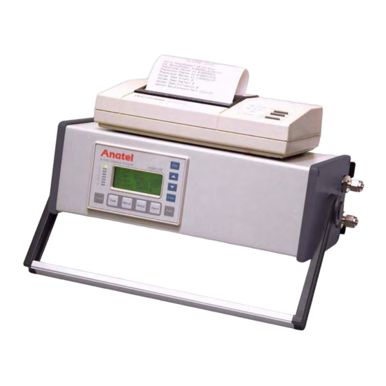
A1000 - Instrument Installation 17 of 176 Instrument Installation Overview The A1000 TOC Analysis System is specifically designed to provide a flexible method of monitoring ultrapure water systems. The most basic A1000 configuration consists of a C80 Controller and S-10 Sensor. These two components are combined with a printer on the S20P to form a portable analysis System. -
Page 18: Unpacking And Inspection
If damage is apparent, notify the freight carrier immediately. Claims must be filed by the customer. Also notify Hach Ultra of any such problems. Include the Serial Number of the damaged unit(s) and the purchase order number with all factory communications. -
Page 19: Software Setup
Fig 2-2 : C80 Logon Screen The Controller display reports that it is establishing communications with the Sensor. If “Sensor Head not communicating” is displayed or either instrument fails to operate, check the connections. Contact Hach Ultra if these initial problems persist. 2.3.2 Software Setup With communications established, you must define the System Time on the C80 Controller and give the S10 a Sensor Name. -
Page 20: Fig 2-3 : Sensor Setup Selections
20 of 176 Instrument Installation - A1000 To set the Controller’s clock/calendar: 1) Press the Setup Key to display the Setup Menu. Sensor Setup: System Setup C80 Setup: Fig 2-3 : Sensor Setup Selections 2) Use the Up and Down Keys to specify System Setup. 3) Press Enter to access its submenu. -
Page 21: Fig 2-6 : Date/Time Setup Selections
A1000 - Instrument Installation 21 of 176 5) Use the Up and Down Keys to highlight the division of the Date/Time display that is to be changed. 6) Press Enter to enable the Controller’s Edit Mode. The flashing cursor becomes an underscore and the key functions change. -
Page 22: Fig 2-9 : Sensor Name Screen
22 of 176 Instrument Installation - A1000 Fig 2-9 : Sensor Name Screen To name a Sensor: 1) With Sensor Setup highlighted on the System Setup, press Enter. Analysis Setup: Display/Print: Sensor Name: Diagnostics: Fig 2-10 : System Setup Menu 2) Specify Sensor Name and press Enter to display that parameter screen. -
Page 23: Hardware Installation
A1000 - Instrument Installation 23 of 176 6) Press Enter to save the new character and advance the cursor to the next. 7) Again scroll through the display using the Up and Down Keys until the desired character is displayed. 8) Press Enter to save the altered character. -
Page 24: Fig 2-13 : S10 Mounting Template
24 of 176 Instrument Installation - A1000 S10 Sensor The S10 Sensor is designed to be a wall-mount unit. The instrument is splash-resistant, but it is not waterproof, and therefore should be installed in a dry and relatively dust-free environment. Do not allow the air flow through the intake and outlet filters located on the bottom of the Sensor to be obstructed or to not get wet. -
Page 25: Plumbing Connections
A1000 - Instrument Installation 25 of 176 S20P Sensor Orientation is important when locating the portable S20P Sensor. The instrument must be maintained in an upright position with the integral C80 Controller’s front panel facing upwards. This precaution assures that the A1000’s measurement cell is flushed completely between analysis cycles. -
Page 26: Fig 2-15 : Isolation Valve
Instrument Installation - A1000 Fig 2-15 : Isolation Valve Hach Ultra provides a 1/4” tube x 1/4” MNPT stainless steel compression fitting that can be inserted in the valve to assist in connection to the Sensor. A 5-foot length of PFA sample tubing and a 10-foot length of polypropylene drain tubing are supplied with each Sensor. -
Page 27: Fig 2-16 : Tubing Installation
A1000 - Instrument Installation 27 of 176 Fig 2-16 : Tubing Installation 5) Using the two wrenches, tighten the compression nut 1-1/4 turns to secure the connection. 6) Repeat step 2 through step 5 to connect the sample tubing to the (customer-supplied) isolation valve. -
Page 28: Communications Connections
28 of 176 Instrument Installation - A1000 7) Repeat step 2 through step 5 to attach the 10-foot polypropylene drain tubing to the WATER OUT port. Run the open end to a suitable drain. 8) Leak test the connections by slowly opening the upstream isolation valve to introduce water into the instrument. -
Page 29: Fig 2-18 : A1000 Sensor, Bottom View
A1000 - Instrument Installation 29 of 176 Fig 2-18 : A1000 Sensor, Bottom View External wiring connections are made by removing the entire I/O Connector Block from the bottom of the Sensor and wiring each I/O cable to the appropriate screw terminals. The connector type and gender of the other end of the cable is determined by the auxiliary device to which it is attached. -
Page 30: Fig 2-19 : A1000 Connector Block
30 of 176 Instrument Installation - A1000 5) Make the connections to the appropriate terminals. Refer to the following sections for detailed information on the specific interface connections: • “Printer Output” on page 91 • “Analog Outputs” on page 99 •... -
Page 31: Power Connections
AC power source. The Sensor’s internal electronics are self- adjusting to accommodate either a 110 VAC or 220 VAC supply. The C80 Controller receives its 9 VDC power through a Hach Ultra-supplied transformer that connects to a 120 VAC adapter. A 230 VAC version is also available. -
Page 32: Sensor Initialization
32 of 176 Instrument Installation - A1000 Sensor Initialization With the plumbing, communications and power connections properly established, the A1000 Sensor can be initialized and placed into operation. Because the cleanliness of commercially available tubing varies (particularly stainless steel), it is suggested that the Sensor’s plumbing be thoroughly flushed. -
Page 33: Network Installation
A1000 - Network Installation 33 of 176 Network Installation General Information As many as eight sensors and eight controllers can be networked together in any configuration to create a diverse combination of A1000 Systems. The controller in a single S20P, for example, can oversee as many as seven additional Sensors, or a single S10 Sensor may be linked to eight separate controllers. -
Page 34: Fig 3-2 : Id To Serial Number Cross-Reference Screen
34 of 176 Network Installation - A1000 Fig 3-2 : ID to Serial Number Cross-Reference Screen 4) Accept this ID-S/N cross-reference, or press Enter to access the Controller’s Edit Mode. The flashing block cursor becomes an underscore. S20P SN: XXXXX S10 SN: XXXXX S20P SN: XXXXX S10 SN: XXXXX... -
Page 35: Controller Address
A1000 - Network Installation 35 of 176 3.2.2 Controller Address Note: Default: Address 9 Fig 3-4 : Controller Address Screen Like A1000 Sensors, each C80 Controller also must have its own unique address on the Network for identification and reporting functions. The Sensor address is pre-configured at the factory to a default of “9,”... - Page 36 36 of 176 Network Installation - A1000 The A-Net Network must be configured as a single trunk line with each A1000 component connected through an individual tee connector using a local cable no longer than 3 feet. The A- Net trunk line can extend a total of 3000 feet not including these local cable lengths. If the trunk line exceeds 500 feet, its cable should be installed in conduit which is free from other cables or AC buses to prevent the potential for electrical interference.
-
Page 37: S20P Network Connections
A1000 - Network Installation 37 of 176 Fig 3-5 : A-Net Communications Connections 3.3.1 S20P Network Connections The local cable must be attached to an S20P Sensor when connecting it to the network. This 3-foot communications cable is provided with each portable Sensor and can be found in its installation kit. -
Page 38: Fig 3-7 : I/O Connector Block
38 of 176 Network Installation - A1000 Fig 3-7 : I/O Connector Block 7) Replace the I/O Connector Block on the bottom of the Sensor, taking care not to pinch any wires, and secure it in place by tightening the thumbscrews. 8) Reconnect the power cord and turn the Sensor ON. -
Page 39: C80 Controller Setup
A1000 - C80 Controller Setup 39 of 176 C80 Controller Setup General Information The C80 Controller provides the user interface with the various Sensors, furnishing data displays and access to individual Sensor parameters. The Controller is either a stand-alone unit or an integral component of the S20P Sensor. User interaction with the C80 Controller is through a consistent interface. -
Page 40: Operational Conventions
40 of 176 C80 Controller Setup - A1000 C80 Controller Edit Keys Table 4-1 : Function Esc Key Saves the displayed setting, exits the current screen and returns to the previous screen. Up and Down Keys Used to specify menu items and parameter values for selection. The Up arrow key moves the cursor up or left within the display while the Down arrow moves the cursor down or right. -
Page 41: Fig 4-2 : Sensor Setup Selections
A1000 - C80 Controller Setup 41 of 176 To adjust the Controller’s display contrast: 1) With any Channel View displayed, press the Setup Key and its menu selections are presented. Sensor Setup: System Setup C80 Setup: Fig 4-2 : Sensor Setup Selections 2) Use the Up and Down Keys to specify C80 Setup. -
Page 42: View Options
42 of 176 C80 Controller Setup - A1000 View Options The View Key determines the type of Sensor information that is presented in the Controller’s LCD display. Three data display formats are offered: 1) Detailed readings for a single Sensor including the current TOC, trend, profile type, resistivity and temperature values. -
Page 43: Multichannel View
A1000 - C80 Controller Setup 43 of 176 Fig 4-6 : Single Channel View The first line of the display identifies the Sensor by its Channel ID number and user-entered name. The remaining lines furnish the following information on the Sensor’s previous analysis cycle: •... -
Page 44: Differential View
44 of 176 C80 Controller Setup - A1000 Fig 4-7 : Multichannel View “PURGE MODE” indicates that water is flowing through the corresponding Sensor’s measurement cell and no analysis is being conducted. In the “CLEAN MODE,” the Sensor’s UV lamp is turned on to oxidize any residual organics while the water sample flows through its measurement cell. -
Page 45: Fig 4-8 : Toc Differential View
A1000 - C80 Controller Setup 45 of 176 Fig 4-8 : TOC Differential View Fig 4-9 : Purge Differential View Anatel Operator Manual... -
Page 46: Channel Display
46 of 176 C80 Controller Setup - A1000 The first two lines of the Differential View identify the primary Sensor, followed by the reference Sensor. The information in the last two lines depends on the common operational state of the two Sensors: •... -
Page 47: Fig 4-11 : Checksum Display
A1000 - C80 Controller Setup 47 of 176 This information may be examined for other associated Sensors simply by pressing the Up and Down Keys once the Channel display is presented. Pressing the Chnl Key twice displays the checksum value of the A1000’s controlling EPROM as well as its current firmware version. - Page 48 48 of 176 C80 Controller Setup - A1000 Anatel Operator Manual...
-
Page 49: Sensor Setup
A1000 - Sensor Setup 49 of 176 Sensor Setup Once they have been installed, A1000 Sensors can begin analysis immediately based on the factory default parameters. The user can selectively alter these default values to tailor the instrument’s operation to the requirements of the particular application. A1000 Sensors run in one of four modes: •... - Page 50 50 of 176 Sensor Setup - A1000 Sensor Default Factory Values (Continued) Table 5-1 : Parameter Default Value Outputs mA Range 4 to 20mA TOC Zero-Scale 0000 ppb TOC Full-Scale 1000 ppb Resistivity Zero-Scale MΩ –cm Resistivity Full-Scale MΩ –cm Temperature Zero-Scale 0000 °C Temperature Full-Scale...
-
Page 51: Fig 5-1 : More Setup Submenu
A1000 - Sensor Setup 51 of 176 3) Press Enter to display its submenu. 4) Specify Analysis Setup and press Enter. 5) Specify More Setup and press Enter to access its submenu. SENSOR NAME Valve at Idle: Factory Default Fig 5-1 : More Setup Submenu Note: This procedure restores all parameters to their factory default values. -
Page 52: Display Units
52 of 176 Sensor Setup - A1000 Display Units Default: Resistivity This Display/Print submenu selection determines which measurement units are logged, displayed and output to the printer. Sample resistivity is reported in megaohm-centimeters and sample conductivity in microsiemens per centimeter. Either may also be selected. To specify the reported display units: 1) With the desired Sensor indicated in any View, press the Setup Key to display its submenu. -
Page 53: Uncompensated Temperature Measurement
5.2.1 Uncompensated Temperature Measurement The Anatel A1000 TOC Analysis System software also can report the raw conductivity, or resistivity, of the sample water. A compensation factor normally is applied to the water temperature in order to adjust it to a 25 °C standard. This calculation provides consistency from one analysis reading to the next. -
Page 54: Fig 5-6 : Display Units Screen
54 of 176 Sensor Setup - A1000 1) With the desired Sensor indicated in any View, press the Setup Key to display its submenu. 2) Use the Up and Down Keys to specify Sensor Setup. 3) Press Enter to access its submenu. 4) Specify Display/Print from among the available selections and press Enter display its options. -
Page 55: Fig 5-7 : Uncompensated Zero-Scale Conductivity Display
A1000 - Sensor Setup 55 of 176 To set the uncompensated output range: 1) With the Sensor specified in any View, press the Setup Key to display its submenu. 2) Use the Up and Down Keys to specify Sensor Setup. 3) Press Enter to display the Sensor Setup Menu. -
Page 56: Fig 5-9 : Uncompensated Full-Scale Conductivity Display
56 of 176 Sensor Setup - A1000 Fig 5-9 : Uncompensated Full-scale Conductivity Display 11) Select DAC Full-Scale and press Enter. 12) Specify Resis/Cond DAC and press Enter to display its full-scale parameter screen. 13) Use the Up and Down Keys to scroll the setting until the desired value is displayed. SENSOR NAME Zero-Scale Conf 01 uS/cm U... -
Page 57: Auto Toc Mode
A1000 - Sensor Setup 57 of 176 A1000 S10 Organics Analyzer S/N xxxxx ID: 2 Name: SENSOR NAME – – – – – – – – – – – – – – – – – – – – – – – – 07/31/2006 TIME COND... -
Page 58: Fig 5-12 : Auto Toc Mode Selection
58 of 176 Sensor Setup - A1000 Fig 5-12 : Auto TOC Mode Selection In this mode, water analyses are conducted automatically by the A1000 Sensor using a patented procedure. TOC measurement uses a microprocessor-controlled photocatalytic process in conjunction with conductivity detection. The initial conductivity of the water sample is determined to establish a reference value. -
Page 59: Auto Toc Software Setup
A1000 - Sensor Setup 59 of 176 During the Oxidation Time, the Sensor’s sample valve is closed, the UV lamp is turned on and oxidation begins. This interval varies depending on the organic content of the water. The nature of the oxidation curve determines the sample to be one of the following Profile Types: Oxidation Profile Types Table 5-2 : Profile Type Abbreviation Description... - Page 60 60 of 176 Sensor Setup - A1000 4) Specify Analysis Setup from among the available selections and press Enter to display its options. The Times & Rate Menu offers the following Sensor-specific analysis parameters: Times and Rate Menu Parameters Table 5-3 : Parameter Description Sample Time...
-
Page 61: Fig 5-14 : Sample Time Screen
A1000 - Sensor Setup 61 of 176 2) Press Enter to access its parameter screen. The current Sample Time is displayed in an hour:minute:second format and represents duration, not clock time. The flashing block cursor highlights the hour division. 3) Use the Up and Down Keys to specify the time division to be changed. Fig 5-14 : Sample Time Screen 4) Press Enter to enable the Controller’s Edit Mode and the flashing block becomes an underscore. - Page 62 62 of 176 Sensor Setup - A1000 7) Repeat the editing process with each time division until the desired Sample Time has been entered into the display. 8) Press Esc twice to retain the setting and return to the Times & Rate Menu. Cycle Time Default: 0 minutes The Cycle Time is user-selectable from 00:00:00 to 17:59:59 and defines the minimum duration...
-
Page 63: Fig 5-17 : Analyze Rate Screen
A1000 - Sensor Setup 63 of 176 Fig 5-17 : Analyze Rate Screen 4) Press Enter to save the specified Analyze Rate. 5) Press the Esc Key twice to retain the setting and return to the Analysis Setup Menu. Note: When enabled, the Fast Analyze Rate is reported on the Auto TOC Printout (see “Auto TOC Printout”... -
Page 64: Fig 5-18 : Valve At Idle Screen
This is not a calibration procedure! changing the TOC multiplier will significantly affect analysis results. Do not alter this setting without instructions from Hach Ultra. The TOC Multiplier is a variable scaling factor that is applied to the calculated TOC value in order to determine the reported TOC. -
Page 65: Fig 5-19 : Toc Multiplier Screen
A1000 - Sensor Setup 65 of 176 Fig 5-19 : TOC Multiplier Screen To change the TOC Multiplier: 1) With the desired Sensor indicated in any View, press the Setup Key to display its submenu. 2) Use the Up and Down Keys to specify Sensor Setup. 3) Press Enter to access its submenu. -
Page 66: Auto Toc Printout
66 of 176 Sensor Setup - A1000 5.3.2 Auto TOC Printout Default: Continuous The Printer Setup parameter determines the format of analysis printouts as well as the frequency at which they are output to the Sensor’s local printer. The TOC Format reports an individual Sensor’s values while the Diff Format reports the differential values between two A1000 Sensors. -
Page 67: Fig 5-21 : Toc Printout
A1000 - Sensor Setup 67 of 176 A1000 S10 Organics Analyzer S/N XXXXX ID: 1 Name: SENSOR NAME FAST Analyze Rate SAMPLE CYCLE LIMIT TIME TIME MULTIPLY [PPB] [hh:mm:ss] [hh:mm:ss] – – – – – – – – – – – – – – – – – – – – – – – – – – – – – – 07/31/2007 TIME TREND... -
Page 68: Fig 5-23 : Toc Print Submenu
68 of 176 Sensor Setup - A1000 5) Specify TOC Print and press Enter. 6) Use the Up and Down Keys to specify one of the two TOC Print outputs. SENSOR NAME √ Continuous Paper Saver: Fig 5-23 : TOC Print Submenu 7. -
Page 69: Purge Mode
A1000 - Sensor Setup 69 of 176 Purge Mode In the Purge Mode, the Sensor’s internal sample valve is open to permit sample water to continuously flow through its measurement cell. This action provides a method of reporting the resistivity (or conductivity) and temperature values on the Controller’s display and on local printouts. -
Page 70: Purge Printouts
70 of 176 Sensor Setup - A1000 5.4.1 Purge Printouts Default: Timed / 1 Minute As with the Auto TOC Mode, there are two potential Purge Print intervals: • Timed generates a purge printout at user-specified intervals. • Paper Saver triggers a purge printout only when the change in the water sample’s resistivity (or conductivity) level exceeds a user-defined percentage in two successive analyses. -
Page 71: Fig 5-28 : Purge Printout
A1000 - Sensor Setup 71 of 176 A1000 S10 Organics Analyzer S/N xxxxx ID: 1 Name: SENSOR NAME – – – – – – – – – – – – – – – – – – – – – – – – – – – – – – 07/31/06 TIME RESIS... -
Page 72: Fig 5-30 : Timed Print Purge Interval Submenu
72 of 176 Sensor Setup - A1000 Timed Purge Print If Timed Purge Print is selected, a flashing block cursor highlights the minutes division. 1) Use the Up and Down Keys to specify the time division to be changed. 2) Press Enter to enable the Controller’s Edit Mode and the flashing block becomes an underscore. -
Page 73: Differential Mode
A1000 - Sensor Setup 73 of 176 1) Use the Up and Down Keys to scroll the value until the desired percentage is displayed. 2) Press Esc to retain the setting and exit the screen. SENSOR NAME % Change in data 10 percent to change Fig 5-32 : Display/Print Submenu... -
Page 74: Referencing Sensors
74 of 176 Sensor Setup - A1000 5.5.2 Referencing Sensors Default: No Reference This software selection specifies the secondary Sensor to which the primary (current) Sensor is referenced. Once a reference assignment is specified, the Differential View is available on the primary Sensor and, when specified, the comparative measurements are output to the local printer (see “Differential Printout”... -
Page 75: Differential Printout
A1000 - Sensor Setup 75 of 176 Note: The values of the referenced Sensor are always subtracted from those of the primary Sensor. 6) Use the Up and Down Keys until the desired reference Sensor’s Channel ID Number is displayed. SENSOR NAME is referenced to SENSOR NAME... -
Page 76: Fig 5-38 : Differential Printout
76 of 176 Sensor Setup - A1000 A1000 S10 Organics Analyzer S/N xxxxx This Sensor: ID: 1 Name: SENSOR NAME • Ref Sensor: ID: 5 Name: SENSOR NAME SAMPLE CYCLE LIMIT TIME TIME MULTIPLY [PPB] [hh:mm:ss] [hh:mm:ss] 00:01:00 00:00:00 1.000 –... -
Page 77: Manual Mode
A1000 - Sensor Setup 77 of 176 The Differential Printout reports the values shown in Table 5-7. Differential Printout Values Table 5-7 : Parameter Description Sensor Model Number of the primary Sensor. Serial Number of the primary Sensor. Its Channel ID Number of both Sensors. Name User-entered name of both Sensors. -
Page 78: Manual Samples
78 of 176 Sensor Setup - A1000 5.6.1 Manual Samples Access to the Sensor by other connected C80 Controllers is denied while the instrument is in the Manual Sample or Oxidation State. Access is restored when the Manual Mode is exited. To conduct a manual measurement: 1) With the desired Sensor indicated in any View, press the Manual Key to access its menu selections. -
Page 79: Fig 5-42 : Manual Oxidize State
A1000 - Sensor Setup 79 of 176 Fig 5-42 : Manual Oxidize State 9) Press Enter to stop sampling and the analysis continues with the Oxidation stage. Once oxidation is complete, the sample’s TOC value is displayed. 10) Another manual operation can be initiated by pressing Enter again. 11) The Manual Mode can be terminated at any time by pressing the eKey to exit the screen. - Page 80 80 of 176 Sensor Setup - A1000 Anatel Operator Manual...
-
Page 81: A1000 Alarms
A1000 - A1000 Alarms 81 of 176 A1000 Alarms Alarm Overview A Sensor’s absolute or differential TOC level can be monitored for fluctuations, an excursion triggering an alarm condition. The type and limit of the alarm can be independently defined for each instrument. -
Page 82: Fig 6-2 : Sensor Setup Menu
82 of 176 A1000 Alarms - A1000 Analysis Setup: Display/Print: Sensor Name: Diagnostics: Fig 6-2 : Sensor Setup Menu 5) Specify and select More Setup. SENSOR NAME Times & Rate Analog Setup: More Setup: Fig 6-3 : Sensor Setup Menu 6) Specify and select Alarm Setup to display its submenu. -
Page 83: Fig 6-5 : Toc Alarm Limit Screen
A1000 - A1000 Alarms 83 of 176 Fig 6-5 : TOC Alarm Limit Screen 10) Press Enter to enable the Controller’s Edit Mode and the flashing block cursor becomes an underscore. 11) Use the Up and Down Keys to scroll until the desired value is displayed. 12) Press Enter to retain the pair’s setting. -
Page 84: Beeper Setup
84 of 176 A1000 Alarms - A1000 6.2.2 Beeper Setup Default: Enabled The Beeper Setup is a global parameter for sounding the Controller’s audible alarm in the event of a TOC limit excursion by one of its connected Sensors. The alarm continues to sound until it is acknowledged by pressing the Alarm Key. -
Page 85: Alarm Reporting
A1000 - A1000 Alarms 85 of 176 Alarm Reporting The most common A1000 fault condition is a Sensor that measures a TOC value greater than its specified TOC or Differential Alarm setting (see “Alarm Setup” on page 81). There are several ways in which an alarm condition is reported: •... -
Page 86: Uncompensated Temperature Alarms
86 of 176 A1000 Alarms - A1000 6.3.1 Uncompensated Temperature Alarms Alarms are reported for conductivity excursions only in the Uncompensated Mode (see “Uncompensated Temperature Measurement” on page 53) and require that “Conductv” and “Uncompensated” be selected in the Resistivity/Conductivity Parameter Screen. In the Auto TOC mode, the alarm limit is checked at the end of each analysis cycle, In the Purge mode, it is checked every 15 seconds. -
Page 87: Fig 6-10 : Alarm Setup Menu
A1000 - A1000 Alarms 87 of 176 Fig 6-10 : Alarm Setup Menu Note: The Cond Alarm parameter does not appear unless the display was set to “Conductv” (see “Auto TOC Software Setup” on page 59). To access the Sensor’s Alarm Setup parameters: 1) Press the Setup Key to display its menu selections. -
Page 88: Fig 6-11 : Uncompensated Conductivity Alarm
88 of 176 A1000 Alarms - A1000 Fig 6-11 : Uncompensated Conductivity Alarm When the uncompensated limit is exceeded, an alarm is generated and several things occur: • The LED corresponding to the Sensor’s Channel ID begins flashing red on all of its associated A1000 C80 Controllers. -
Page 89: Alarm Acknowledgement
A1000 - A1000 Alarms 89 of 176 Alarm Acknowledgement A limit excursion is acknowledged by specifying the appropriate Sensor and then pressing the Alarm Key. Acknowledgement stops the Controller’s LCD from flashing, stops the flashing red Channel ID, and silences the audible warning. If more than one alarm has been detected, all must be acknowledged before these fault indications are terminated. -
Page 90: Fig 6-13 : Error Code Reporting
90 of 176 A1000 Alarms - A1000 Fig 6-13 : Error Code Reporting The Alarm Key is also used to acknowledge Sensor Errors. When a Sensor error is detected, it displays the following information: • Affected Sensor’s Channel ID and its userentered Name. •... -
Page 91: Printer Output
4) Feed the interface wiring through one of the five holes at the end of the Connector Block cover and along the corresponding slot in the foam padding. Note: When purchased from Hach Ultra, the local printer’s (PN FG 2996301) interface cable is provided. Fig 7-1 : External Printer Wiring 5) Make the necessary serial connections to the Sensor’s PRINTER port as shown. -
Page 92: Software Setup
92 of 176 Printer Output - A1000 Seiko Instruments Inc. DPU-414 Type II Thermal Printer DIP Switch Defaults Table 7-1 : DIP Switch 1 DIP Switch 2 Serial Interface 8 Data Bits CR only No Parity 40-Column Even Parity Standard Characters 1200 Baud 0 Font Setting 1200 Baud... -
Page 93: Data Logger
A1000 - Printer Output 93 of 176 4) Specify Print Format and then press Enter to display its two output options: • TOC Format outputs the current date, the TIME at which each sample was captured, the measured TOC in PPB, the current TOC value as a percentage of its Alarm Limit, the directional TREND over the last hour, RESIStivity (or CONDuctivity) and TEMPerature values, and the CuRVe (Profile) TYPe of the sample. -
Page 94: Fig 7-3 : Print Submenu
94 of 176 Printer Output - A1000 approximately two and a half days worth of information before it begins writing over the earliest data recorded. To access Data Logger information: 1) With the desired Sensor specified in any View, press the Print Key to access its submenu. -
Page 95: Printouts
A1000 - Printer Output 95 of 176 7.2.3 Printouts The Printouts option provides detailed setup information on the individual instruments. These two hardcopy outputs list all of the Sensor’s operational parameters and its factory configuration parameters. Fig 7-5 : Printouts Screen To generate Printouts of this parameter information: 1) With the desired Sensor specified in any View, press the Print Key to access its menu. -
Page 96: Fig 7-7 : Sensor Factory Configuration Printout
96 of 176 Printer Output - A1000 4) Use the Up and Down Keys to specify the desired Printout function. 5) Press Enter to generate the specified output. The information in both Printouts is preceded by the following Sensor-specific header data: •... -
Page 97: Fig 7-8 : Sensor Parameter Settings Printout
A1000 - Printer Output 97 of 176 A1000 S10 Organics Analyzer S/N xxxxx ID: 1 Name: SENSOR NAME Sensor Parameter Settings 07/31/06 14:32:41 Sample Time = 00:01:00 Cycle Time = 00:00:00 TOC Alarm Limit = 100 Diff Alarm Limit = 000 Reference Sensor = 1 ID Number = 2 ID Name = SN-1001... - Page 98 98 of 176 Printer Output - A1000 Anatel Operator Manual...
-
Page 99: Analog Outputs
A1000 - Analog Outputs 99 of 176 Analog Outputs A1000 Sensors provide two methods for outputting signals to external analog devices. The first offers TOC data through the dedicated 4–20 mA port located on the instrument’s Connector Block; the second outputs resistivity and/or temperature data to optional External DAC (Digital -to-Analog Conversion) Modules via the Sensor’s DIAGNOSTICS port. -
Page 100: Software Setup
100 of 176 Analog Outputs - A1000 5) Make the necessary positive and ground connections to the Sensor’s 4-20mA terminals. 6) Replace the metal strain relief plate. Fig 8-1 : Current Output Wiring Fig 8-2 : Voltage Output Wiring 7) Replace the I/O Connector Block on the bottom of the Sensor, taking care not to pinch any wires, and secure it in place by tightening the thumbscrews. -
Page 101: Fig 8-3 : Setup Menu
A1000 - Analog Outputs 101 of 176 Sensor Setup: System Setup: C80 Setup: Fig 8-3 : Setup Menu 2) Use the Up and Down Keys to specify Sensor Setup. 3) Press Enter to display the Sensor Setup Menu. Analysis Setup: Display/Print: Sensor Name: Diagnostics:... -
Page 102: Fig 8-6 : Dac Range Setup Menu
102 of 176 Analog Outputs - A1000 SENSOR NAME DAC mA Range: DAC Zero-Scale: DAC Full-Scale: Fig 8-6 : DAC Range Setup Menu Analog Output Range Default: 4 to 20 mA, optional: 0 to 20 mA The mA Range internally defines the span (4 to 20 or 0 to 20 mA) of the analog output that is presented at the Sensor’s 4–20 mA port. -
Page 103: Fig 8-8 : Zero-Scale Toc Screen
A1000 - Analog Outputs 103 of 176 TOC Output Range Defaults: Zero-Scale – 0000 ppb, Full–Scale – 1000 ppb , Range: 0000 to 9999 These settings define the lower and upper ppb limits proportional to the mA Range setting. The analog signal generated at the conclusion of each analysis is converted to a scaled TOC value for display and reporting purposes. -
Page 104: Fig 8-10 : Toc Dac Submenu
104 of 176 Analog Outputs - A1000 2) Press Enter to display its menu selections. 3) Specify TOC DAC and press Enter to display its zero-scale parameter screen. The flashing block cursor highlights the first pair of digits. 4) Use the Up and Down Keys to highlight the digit pair that is to be changed. 5) Press Enter to enable the Controller’s Edit Mode and the flashing block becomes an underscore. -
Page 105: Fig 8-13 : Toc Dac Submenu
A1000 - Analog Outputs 105 of 176 Note: The Full-Scale TOC value must be greater than the Zero-Scale TOC value. 11) Specify TOC DAC once again and press Enter to display its full-scale parameter screen. The flashing block cursor highlights the first pair of digits. 12) Use the same procedure as that described in step 4 through... -
Page 106: Optional Resistivity And Temperature Outputs
(AWG 24 is recommended). Two DAC Modules can be daisy-chained to obtain both resistivity and temperature data and can be positioned up to 50 feet from the associated Sensor (Hach Ultra provides 5 feet of cabling). Anatel... -
Page 107: Fig 8-15 : Connector Block For The A1000
A1000 - Analog Outputs 107 of 176 Fig 8-15 : Connector Block for the A1000 These auxiliary analog connections are made on the Senor’s I/O Connector Block as follows: 1) Turn the Sensor OFF and disconnect the power cord from its source. 2) Remove the I/O Connector Block from the bottom of the Sensor by loosening the four thumbscrews. -
Page 108: Software Setup
108 of 176 Analog Outputs - A1000 Fig 8-16 : External DAC Wiring Note: The S20P Sensor’s integral printer is wired to its BIAS port. An external +12 VDC supply must be provided for any DAC Modules in these instances. 5) Make the necessary connections to the Sensor’s DIAGNOSTICS port as shown. -
Page 109: Fig 8-17 : Setup Menu
A1000 - Analog Outputs 109 of 176 External DAC Module Default: No This software switch enables and disables the resistivity and temperature output to an External DAC Module. The Module converts the output into an analog signal for processing by a variety of devices. -
Page 110: Fig 8-19 : External Dac Module Screen
110 of 176 Analog Outputs - A1000 Fig 8-19 : External DAC Module Screen Analog Output Range Default: 4 to 20 mA, Optional: 0 to 20 mA The mA Range internally defines the span (4 to 20 or 0 to 20 mA) of the analog output that is presented at the Sensor’s DIAGNOSTICS port. -
Page 111: Fig 8-21 : Zero-Scale Resistivity Screen
A1000 - Analog Outputs 111 of 176 To set the Sensor’s mA Range: 1) With the Analog Setup Menu displayed, select DAC Range to display its menu selections. 2) Specify mA Range and press Enter to display its parameter screen. 3) Use the Up and Down Keys to specify the desired analog output range. -
Page 112: Fig 8-22 : Dac Zero-Scale Menu
112 of 176 Analog Outputs - A1000 SENSOR NAME DAC mA Range: DAC Zero-Scale: DAC Full-Scale: Fig 8-22 : DAC Zero-Scale Menu Note: Resistivity is output regardless of the Display Units setting (see “Display Units” on page 52). 2) Press Enter to display its menu selections. 3) Specify Resis DAC and press Enter to display its zero-scale parameter screen. -
Page 113: Fig 8-25 : Zero-Scale Parameter Screen
A1000 - Analog Outputs 113 of 176 8) Use the Up and Down Keys to scroll the setting until the desired value is displayed. SENSOR NAME Full-Scale Resis 10 MΩ-cm to change Fig 8-25 : Zero-Scale Parameter Screen Note: The Full-Scale Resis value must be greater than the Zero-Scale Resis value. 9) Press Esc twice to retain the Full-Scale Resis setting and return to the DAC Range Menu. -
Page 114: Fig 8-27 : Dac Range Menu
114 of 176 Analog Outputs - A1000 To set the temperature output range: 1) With the DAC Range Menu displayed, use the Up and Down Keys to specify DAC Zero-Scale. SENSOR NAME DAC mA Range: DAC Zero-Scale: DAC Full-Scale: Fig 8-27 : DAC Range Menu 2) Press Enter to display its menu selections. -
Page 115: Fig 8-30 : Full-Scale Temperature Screen
A1000 - Analog Outputs 115 of 176 Fig 8-30 : Full-Scale Temperature Screen Note: The Full-Scale Temp value must be greater than the Zero-Scale Temp value. 9) Press Esc twice to retain the Full-Scale Temp setting and return to the DAC Range Menu. -
Page 116: Fig 8-31 : Dac Error Output Screen
116 of 176 Analog Outputs - A1000 DAC Error Output Default: Minimum Output The user may select from among three states to be output when a fatal error is encountered which causes the Sensor to abort its current analysis. This fixed signal is global for all analog outputs and can be used externally to indicate an error condition. -
Page 117: Digital Inputs And Outputs
A1000 - Digital Inputs and Outputs 117 of 176 Digital Inputs and Outputs The Sensor’s I/O Connector Block is equipped with two opto-isolated inputs and two opto- isolated outputs for receiving and sending digital signals. The digital inputs allow limited supervisory control of the Sensor by a remote device or switch. -
Page 118: Software Setup
118 of 176 Digital Inputs and Outputs - A1000 • IN1* allows external initiation of an analysis. When Input #2 selects the Auto TOC Mode, a high-to-low state transition forces the Sensor to initiate an analysis cycle. • IN2* selects between the Auto TOC (high state) and the Purge (low state) Mode. State transitions are ignored on IN1* when the Sensor is in the Purge Mode. -
Page 119: Fig 9-2 : Special Modes Screen
A1000 - Digital Inputs and Outputs 119 of 176 Fig 9-2 : Special Modes Screen To enable external Digital Control: 1) With the Sensor specified in any View, press the Manual Key to display its submenu. SENSOR NAME Modes: Manual Samples: Fig 9-3 : Manual Submenu 2) Use the Up and Down Keys to specify Modes. -
Page 120: Digital Outputs
120 of 176 Digital Inputs and Outputs - A1000 6) Press Enter to enable external digital control of the Sensor. Activating this mode inserts “r/c” anywhere the Sensor’s TOC status is displayed to indicate that it is under remote control. 7) Press Esc to exit the Special Modes Screen. -
Page 121: 10 12 Vdc Bias Output
A1000 - 12 VDC Bias Output 121 of 176 10 12 VDC Bias Output A1000 Sensors are equipped with a Bias connection. It can supply power for such auxiliary devices as the External DAC Modules in order to obtain resistivity and temperature data from S10 Sensors. - Page 122 122 of 176 12 VDC Bias Output - A1000 Anatel Operator Manual...
-
Page 123: 11 Serial Communications
A1000 - Serial Communications 123 of 176 11 Serial Communications A1000 Sensors are equipped with a bidirectional serial interface that allows them to communicate with a wide variety of intelligent devices such as a Programmable Logic Controller (PLC) or a host computer. The wiring is configured as for any PC-compatible Data Terminal Equipment (DTE) interface. -
Page 124: A1000 Command Set
124 of 176 Serial Communications - A1000 DB-9 to DB-25 Pin Correspondance Table 11-1 : Signal DB-9 DB-25 Function Transmit Data Output Input Receive Data Input Output Request-To-Send Output Input Clear-To-Send Input Output Data Set Ready Input Output Signal Ground –... -
Page 125: Mode Set Commands
A1000 - Serial Communications 125 of 176 11.2.1 Mode Set Commands The Mode Set commands are used to determine the Sensor’s operational mode. Any changes generate an automatic printout. Mode Set Commands Table 11-3 : Command Function Comment Self-Clean Mode Valve open, lamp on Auto TOC Mode Continuous TOC analyses... - Page 126 126 of 176 Serial Communications - A1000 Parameter Set Commands (Continued) Table 11-4 : Command Function Section Purge Mode Print Strategy ( 0 = Continuous, 1 = Paper Saver) “Purge Printouts” on page 70 Active Alarm Type (0 = absolute ppb, 1 = differential ppb, “Software Setup”...
-
Page 127: Data Read Commands
A1000 - Serial Communications 127 of 176 11.2.3 Data Read Commands Data Read functions return multiple values, the string terminated with a <cr><lf>. Data Read Commands Table 11-5 : Command Function Comment Notes Read Sensor Data Returns one line of time stamped data from The mode is: when the unit began oxidation: mm/dd/yyyy, 1 = Auto TOC... - Page 128 128 of 176 Serial Communications - A1000 Anatel Operator Manual...
-
Page 129: 12 A1000 Maintenance
Repairs are performed only at Hach Ultra Service Centers due to the specialized equipment and parts required. Contact Hach Ultra for more information or to schedule a service plan. If problems persist after performing maintenance or repair procedures, contact the Hach Ultra Customer Service department at 800.866.7889 or +1-541.472.6500. -
Page 130: Fig 12-1 : Manual Submenu
130 of 176 A1000 Maintenance - A1000 1) With the desired Sensor indicated in any View, press the Manual Key to display its menu. SENSOR NAME Modes: Manual Samples: Fig 12-1 : Manual Submenu 2) Use the Up and Down Keys to specify Modes. 3) Press Enter to display its submenu. -
Page 131: Prepartory Maintenance Procedures
A1000 - A1000 Maintenance 131 of 176 The A1000’s external case can be cleaned by wiping it with a soft cloth moistened with water. Do not use abrasive cleaners as they can scratch the instrument’s painted finish and do not subject the enclosure to a direct spray as it could damage internal components. -
Page 132: Uv Lamp Replacement
UV Lamp Replacement Kits are available to perform on-site lamp exchange. Alternatively, the Sensor may be returned to Hach Ultra for lamp replacement. The Sensor logs UV lamp usage based on its total hours of operation and advises when replacement is warranted. -
Page 133: Fig 12-5 : Exploded View Of Lamp
A1000 - A1000 Maintenance 133 of 176 3) Remove the Sensor’s Water I/O Cover as outlined in “Prepartory Maintenance Procedures” on page 131 to access the UV lamp assembly. 4) Remove the plastic lamp assembly cover. 5) Disconnect the heater connector and unplug the two UV lamp plugs by pulling them straight out of their sockets. -
Page 134: Fig 12-6 : Analyzer Module Assembly
134 of 176 A1000 Maintenance - A1000 Fig 12-6 : Analyzer Module Assembly WARNING DO NOT touch the quartz window or the UV lamp. 7) Gently remove the UV lamp assembly from the enclosure. Discard the standoffs, the septum and the O-Ring located inside the housing. 8) Install the new O-Ring and septum. - Page 135 A1000 - A1000 Maintenance 135 of 176 CAUTION: Tighten the hex bolts carefully. Uneven or undertightening will result in a faulty seal. 10) Install the new standoffs, replace the hex bolts and tighten all three evenly until some resistance is felt. Alternately torque the bolts until they seat, then tighten them another 1/8-turn.
-
Page 136: Sample Valve
136 of 176 A1000 Maintenance - A1000 Fig 12-8 : Resetting the Lamp Counter To reset the Sensor’s UV Lamp counter: 19) With the appropriate Sensor specified in any View, press Setup to access its submenu. 20) Specify Sensor Setup and press Enter. 21) Specify Analysis Setup and press Enter. -
Page 137: Fig 12-9 : Modes Menu
A1000 - A1000 Maintenance 137 of 176 In either instance, the sample valve should be backflushed and possibly disassembled and cleaned to restore normal flow. If a clogged sample valve is a recurring problem, a Prefilter Kit (P/ N FG2000901) can be installed to reduce the need for frequent disassembly and cleaning of the sample valve. -
Page 138: Fig 12-10 : Sample Valve, Exploded View
138 of 176 A1000 Maintenance - A1000 Fig 12-10 : Sample Valve, Exploded View 16) Use a flathead screwdriver to unscrew and remove the plunger housing. 17) Check the housing to verify that the plunger moves freely. Clean any debris from the housing. -
Page 139: Air Filter Cleaning
A1000 - A1000 Maintenance 139 of 176 CAUTION: Do not overtighten. 20) Replace the valve coil, taking care not to damage its wire. Route the wire around the coil rather than between it and the UV lamp assembly. 21) Secure the coil on the sample valve assembly with the 9/16” locknut. Air Filter Cleaning 12.6 Each A1000 Sensor is equipped with air filters which can become clogged over time, reducing... -
Page 140: Fig 12-12 : Electronics I/O Assembly, Exploded View
140 of 176 A1000 Maintenance - A1000 CAUTION: Any logged data will be lost and an Error Code “4–Data Log Corrupt” will be reported when the battery is replaced. Print the data log as described in “Printouts” on page 95 for a copy of the data. -
Page 141: Printer Maintenance
The appearance of a red stripe along the edge of the paper is an indication that the roll is getting low. When the paper runs out, the printer’s red OFF LINE/PAPER END LED begins flashing. Additional thermal paper rolls are available from Hach Ultra. Note: If paper has run out and the A1000 has sent data to the printer, the green ON LINE LED also flashes. -
Page 142: Fig 12-13 : Trimming The Paper Roll
142 of 176 A1000 Maintenance - A1000 Fig 12-13 : Trimming the Paper Roll 4) Insert the point of the “V” into the appropriate slot, feeding the paper from the bottom of the roll. The OFF LINE/PAPER END LED stops flashing and when the paper is inserted properly. -
Page 143: 13 Troubleshooting
A1000 - Troubleshooting 143 of 176 13 Troubleshooting In addition to the standard self-tests conducted by the Sensor during its analyses, an extended diagnostic and reporting facility is incorporated to inform the user about the nature of a problem. Error Codes, in conjunction with user-initiated diagnostic tests, serve to isolate the source of the problem. - Page 144 144 of 176 Troubleshooting - A1000 A1000 Electromechanical Error Codes Table 13-1 : Code Message Indication Bad ROM Hardware failure Bad RAM Hardware failure Watchdog Timeout Hardware failure Data Log Corrupt Invalid data log (hardware failure or battery removed) Bad DUART Hardware failure Bad NET Power Hardware failure...
-
Page 145: Troubleshooting
“Lithium Battery Replacement” on page 139). A “Network Problem (18)” indicates faulty communications; check A-Net wiring and contact Hach Ultra if the problem persists. The Analysis Errors listed in Table 13-3 warrant a general check to verify that your isolation valve is open and the Sensor’s solenoid valve (see... - Page 146 An alert that the quality of the sample water is outside the instrument’s optimum performance range. Measure the resistivity of the sample water. Large discrepancies in the measurements may be due to a hardware failure; contact Hach Ultra. Reports a suspended analysis cycle and does not affect Sensor operation.
-
Page 147: 13.2.1 Purging The Instrument
A1000 - Troubleshooting 147 of 176 13.2.1 Purging the Instrument CAUTION: Remember that an instrument stored in a warehouse in the winter can be freeze-damaged if water is left inside and a unit shipped from a warm climate to a cold climate is exposed to extreme temperatures en route. -
Page 148: Sensor Diagnostics
The instrument is ready for shipment or storage. Fig 13-1 : Purging the A1000 Measurement Cell Note: For assistance in performing this procedure, call Hach Ultra at 800.866.7889 or +1-541.472.6500 for assistance. Sensor Diagnostics 13.3 Diagnostic tests conducted on individual Sensors can be quite helpful in isolating the source of a reported error. -
Page 149: 13.3.1 Electronics Tests
A1000 - Troubleshooting 149 of 176 SENSOR NAME Electronics: Cell: I/O: Fig 13-2 : Diagnostics Menu 5) Specify the desired diagnostic area and then press Enter to display its function. 13.3.1 Electronics Tests The Sensor’s electronic diagnostics are divided into three tests: •... - Page 150 • Printer Test confirms all characters are printing. 2) Press Enter to execute the chosen operation. The results of the test are presented on the Controller’s display and a printout is generated. Contact Hach Ultra if the Sensor fails any of these tests.
-
Page 151: 13.3.2 Cell Tests
A1000 - Troubleshooting 151 of 176 13.3.2 Cell Tests These tests facilitate manual control of the Sensor’s ultraviolet lamp and its internal sample valve. Diagnostics testing interrupts the current TOC analysis. Normal analysis resumes upon termination of the test. Fig 13-4 : Cell Diagnostics Screen To check the status of these two Sensor components: 1) With the Sensor’s Diagnostics Menu displayed, specify Cell and press Enter to access its options. -
Page 152: 13.3.3 I/O Tests
3) Press Enter to execute the test. The results are presented on the Controller display and a corresponding printout is generated. If the Sensor fails either of the tests, check the wiring before contacting Hach Ultra for assistance. 4) Press Esc repeatedly in order to return to previous display screens. -
Page 153: 13.3.4 Network Test
A1000 - Troubleshooting 153 of 176 Fig 13-6 : RS-232 Loopback Wiring Fig 13-7 : Digital I/O Loopback Wiring 13.3.4 Network Test The Network Test provides a method of verifying that a Sensor is interfacing with its associated Controller. This communications check can be performed on any A1000 Sensor to verify proper communications without affecting A-Net operation. - Page 154 If the Sensor continues to fail the Network Test, execute a Memory test (as outlined “Electronics Tests” on page 149) to generate a printout of the instrument’s recorded communications errors and then contact Hach Ultra. Anatel Operator Manual...
-
Page 155: Appendix A:service Procedures
• All analyzers returned for repair or replacement must be thoroughly cleaned and all process material removed. • Sludge contains bacteria that could be hazardous to Hach Ultra personnel. If a contaminated unit is received, Hach Ultra reserves the right to have the unit removed and destroyed by a hazardous material disposal team at the shipper’s expense. -
Page 156: Technical Support Information
Please provide name, company, phone, fax, model number, serial number and comment or question. Hach Ultra Analytics 5600 Lindbergh Drive Loveland, CO 80538 Global Headquarters Service Department 6, route de Compois, C.P. -
Page 157: Appendix B:specifications And Options
157 of 176 Appendix B: Specifications and Options The Anatel A1000 TOC Analytical System is specifically designed for use in applications that monitor ultrapure water with a typical resistivity greater than 5MΩ-cm (as low as 1 megaohm- cm for pH neutral waters) compensated to 25°C. -
Page 158: A1000 Physical Specifications
158 of 176 Specifications and Options - A1000 B.1.2 A1000 Physical Specifications General Installation Category II, IEC 1010 Pollution Degree 2, IEC 664 Indoor Use Only A1000 Network Type RS-485 Maximum Number of Sensors 8 Maximum Number of C80 Controllers (any configuration) Maximum Network Length 1 km (3,000 ft) Network Cabling... -
Page 159: S10 Sensor Specifications
A1000 - Specifications and Options 159 of 176 S10 Sensor Specifications P/N FG 1000401 The S10 Sensor is the basic analysis component in the A1000 TOC Analytical System. Display Main 1-line x 16-character Super-Twist LCD Backlighting Yellow LED Character Height 0.163 in. -
Page 160: Thermal Printer Specifications
S10 Sensor and is integrated into the design of the S20P Sensor. The S20P printer’s onboard NiCad battery is not field-replaceable; contact Hach Ultra for replacement. The battery can be recharged, however, by turning the printer “OFF” and the S20P “ON”... -
Page 161: Sample Time
A1000 - Specifications and Options 161 of 176 Sample Time During the Sample Time, the Sensor’s sample valve is open to allow the measurement cell to purge of any residual contamination. This parameter is set as outlined in “Sample Time” on page An empirical method for determining an appropriate Sample Time for any flow rate is to switch the instrument into the Purge Mode at the end of an oxidation cycle and note the time it takes... - Page 162 162 of 176 Specifications and Options - A1000 Fig B-3 : P3-Type Oxidation Curve A1000 Sensors continuously monitor conductivity and temperature during analysis to ensure complete oxidation (100% yield) of the sample. The relationship between conductivity and time is called the “oxidation curve.” Three forms of oxidation curve are reported: •...
-
Page 163: Appendix C:certifications
A1000 - Certifications 163 of 176 Appendix C: Certifications Overview This section contains the WEEE statement and any Certificates of Conformity. For more information, contact a local Hach Ultra representative or contact the factory at 800-866-7889 or +1-541-472-6500. Anatel Operator Manual... - Page 164 164 of 176 Certifications - A1000 DECLARATION OF CONFORMITY (according to ISO/IEC Guide 22 and EN 45014) Anatel Corporation ’ ANUFACTURER 5600 Lindbergh Drive ’ ANUFACTURER DDRESS Loveland, Colorado 80538 U.S.A. declares that the product A1000 Total Organic Carbon (TOC) Analysis System, inclusive of model(s): •...
-
Page 165: Appendix D:glossary
A1000 - Glossary 165 of 176 Appendix D: Glossary Several of the terms used throughout this User Guide have specific meaning within high-purity water applications. Conductivity A measure of the flow of electrical current through water. This conductance, very low with high-purity deionized water, is the reciprocal of resistivity and is measured in microsiemens per centimeter (µS/cm). - Page 166 166 of 176 Glossary - A1000 Anatel Operator Manual...
-
Page 167: Appendix E:sensor Log
A1000 - Sensor Log 167 of 176 Appendix E: Sensor Log Sensor Log Table E-1 : Channel Number Sensor Name Location Model and Serial Installation Date Number Anatel Operator Manual... - Page 168 168 of 176 Sensor Log - A1000 Anatel Operator Manual...
- Page 169 A1000 - Annex 169 of 176 Annex Tables and illustrations Fig 2-1 : Passive Terminator Location............. 18 Fig 2-2 : C80 Logon Screen ................19 Fig 2-3 : Sensor Setup Selections ..............20 Fig 2-4 : Sensor Time Selection ..............20 Fig 2-5 : System Time Screen .................
- Page 170 170 of 176 Annex - A1000 Fig 5-2 : Factory Defaults Screen..............51 Fig 5-3 : Display/Print Submenu..............52 Fig 5-4 : Display Units Screen ................. 52 Fig 5-5 : A1000 Uncompensated Conductivity Display ........53 Fig 5-6 : Display Units Screen ................. 54 Fig 5-7 : Uncompensated Zero-scale Conductivity Display......
- Page 171 A1000 - Annex 171 of 176 Fig 6-1 : Setup Menu ..................81 Fig 6-2 : Sensor Setup Menu................82 Fig 6-3 : Sensor Setup Menu................82 Fig 6-4 : Alarm Setup Submenu ..............82 Fig 6-5 : TOC Alarm Limit Screen ..............83 Fig 6-6 : Differential Alarm Limit Screen............
- Page 172 172 of 176 Annex - A1000 Fig 8-22 : DAC Zero-Scale Menu ..............112 Fig 8-23 : Zero-Scale Parameter Screen............112 Fig 8-24 : Full-Scale Resistivity Screen............112 Fig 8-25 : Zero-Scale Parameter Screen............113 Fig 8-26 : Zero-Scale Temperature Screen............. 113 Fig 8-27 : DAC Range Menu ................
- Page 173 A1000 - Annex 173 of 176 Fig 13-8 : Network Test Screen............... 153 Fig B-1 : P1-Type Oxidation Curve ..............161 Fig B-2 : P2-Type Oxidation Curve ..............161 Fig B-3 : P3-Type Oxidation Curve ..............162 Table E-1 : Sensor Log ..................167 Anatel Operator Manual...
- Page 174 174 of 176 Annex - A1000 Anatel Operator Manual...
- Page 175 A1000 - User Notes 175 of 176 User Notes Anatel Operator Manual...
- Page 176 176 of 176 User Notes - A1000 end of the book Anatel Operator Manual...
- Page 178 Grants Pass, Oregon 97526 USA Tel 1 800 866 7889 / +1 541 472 6500 Fax +1 541 472 6170 www.hachultra.com © 2007 Hach Ultra Analytics, Inc. All rights reserved. Trademarks are property of their respective owners. Specifications are subject to change without notice.
Need help?
Do you have a question about the Anatel A1000 and is the answer not in the manual?
Questions and answers