Table of Contents
Advertisement
Quick Links
Advertisement
Table of Contents

Related Manuals for Hach Ultra POLYMETRON 9185


Summary of Contents for Hach Ultra POLYMETRON 9185
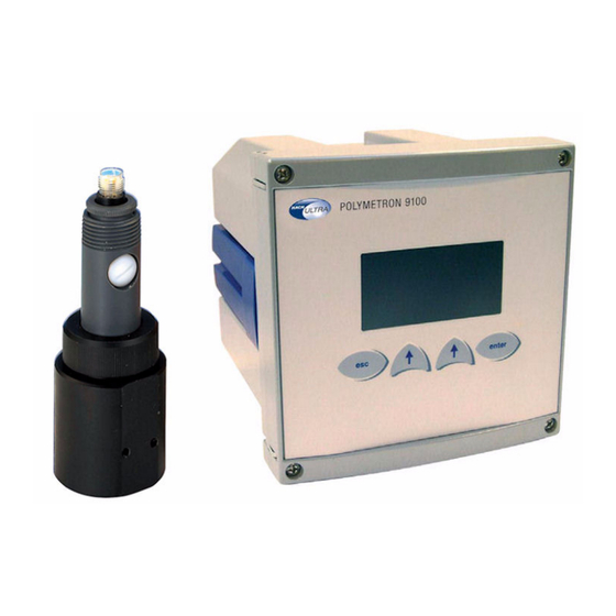
- Page 1 Operator Manual POLYMETRON 9185 221=191=085 - Revision E - 10/12/2007...
-
Page 3: Table Of Contents
OZONMAT 9185 - INSTRUCTION MANUAL SUMMARY Page Presentation of the instrument....................... 5 Introduction ..............................5 Reminders..............................5 Description of the OZONMAT ....................... 10 Synoptic of the instrument ........................10 Technical specifications ........................11 Transmitter section ..........................16 Installation .............................. 20 Unpacking .............................. - Page 4 OZONMAT 9185 - INSTRUCTION MANUAL Start-up, cleaning and maintenance ....................46 Start-up ..............................46 Replacing the membrane......................... 49 Electrode regeneration procedure ......................51 Detection of functional faults........................52 Detection of electrical faults ........................54 APPENDIX 1 ............................A1 APPENDIX 2 ............................A2 APPENDIX 3 ............................
- Page 5 OZONMAT 9185 - INSTRUCTION MANUAL This instrument conforms to the European Directives : - 89/336/CEE modified by the directive 93/68/CEE - 73/23/CEE modified by the directive 93/68/CEE Warning ! This equipment has been tested and found to comply with the limits for Class A digital device, pursuant to Part 15 of the FCC Rules.
- Page 6 Restriction of Hazardous Substances Note: The following only applies to exports of the product into the People’s Republic of China. Marking Products contain toxic or hazardous substances or elements. Environment Protection Use Period Marking (years). Toxic or Hazardous Substances and Elements Hexavalent Polybrom Polybrom...
-
Page 7: Presentation Of The Instrument
OZONMAT 9185 - INSTRUCTION MANUAL Presentation of the instrument Introduction The oxidative properties of ozone are used for disinfecting water in a large number of industrial installations. Continuous monitoring of dissolved ozone levels is therefore essential in order to guarantee the bacteriological quality of water. - Page 8 OZONMAT 9185 - INSTRUCTION MANUAL for example, for an ozoniser generating a concentration of 2 g/m , the maximum concentration X in water, at P = 1 atm, will be as follows: T°C (ppm) 1.28 0.78 0.62 0.48 0.38 0.24 It appears that this concentration is divided by 2 between 5 and 20 °C.
- Page 9 OZONMAT 9185 - INSTRUCTION MANUAL The presence of air in the conduits The exposure to free air of highly ozone-loaded water results in significant degassing: as the ozone content of ambient air is very low compared to that of the sample, exchange therefore occurs, with rapid loss of ozone in the sample.
- Page 10 OZONMAT 9185 - INSTRUCTION MANUAL Measurement principle Measurement is performed using the amperometric method, after diffusion of ozone molecules through a gas permeable membrane. Ozone measurement is based on the Clark cell principle. This amperometric sensor is made up of: - a gold work electrode where the main reaction occurs, - a silver counter-electrode, - an electrolyte, which is an ionic conductor,...
- Page 11 OZONMAT 9185 - INSTRUCTION MANUAL The ozone molecules contained in the sample diffuse through the membrane. O is therefore located in a very thin electrolyte layer between the membrane and the cathode. A constant work potential is applied to the work electrode (cathode) where O is reduced to oxygen.
-
Page 12: Description Of The Ozonmat
OZONMAT 9185 - INSTRUCTION MANUAL Description of the OZONMAT Synoptic of the instrument Figure 2.1 Inlet connector (for DN4/6 tube) Cell Outlet connector (for DN6/8 tube) Membrane Electrode body Filling stopper Electrode Clamping nut Cell cap - 10 Probe cable - 11 Transmitter Page 10 621=191=085... -
Page 13: Technical Specifications
OZONMAT 9185 - INSTRUCTION MANUAL Technical specifications Transmitter dimensions Dimensions are given in mm and in inches. p o ly m e tro n Figure 3.1 Cell dimensions Figure 3.2 (Dimensions are given in mm and in inches). 621=191=085 Page 11... - Page 14 OZONMAT 9185 - INSTRUCTION MANUAL General properties - Measurement range: 0 to 2 mg/l - Temperature compensation - Programmable thresholds, relay outputs - 4-20 mA and 0-20 mA outputs, standard alarm relays and optional RS 485 This instrument complies with the following standards: - Immunity to electromagnetic EN 61326-1997 and EN 61326 A1-1998 disturbances...
- Page 15 OZONMAT 9185 - INSTRUCTION MANUAL Analogue outputs Maximum load 800 Ohms 2 x 0/4... 20 Ma galvanically, insulated, assigned to measurement or to temperature, linear, bi-linear, precision: 0,1 mA Number: 4 Alarms Functions: threshold system alarm - timer Hysteresis: 0-10 % Delay: 0-999 s Breaking power: 250 VAC, 3A maximum...
- Page 16 OZONMAT 9185 - INSTRUCTION MANUAL MAINTENANCE Approximately sample life Between one and six months membrane according to sample µA, ppb-µg/l, ppm-mg/l, °C, °F Units Calibration Electrical zero, chemical zero with ozone--free water, process calibration of the slope by comparison with a laboratory measurement TRANSMITTER Display...
- Page 17 OZONMAT 9185 - INSTRUCTION MANUAL Chemical cleaning kit (optional) Figure 3.4 The complete kit possesses the following reference (220 V version): 09185=A=7100 It is comprised of the following elements: (09184=C=2700) Mounting plate (09184=A=2500) Acidification pump + tubing + tub 09185=A=1800 Overflow vessel for acidification: The no.
-
Page 18: Transmitter Section
OZONMAT 9185 - INSTRUCTION MANUAL Transmitter section Presentation of the transmitter Polymetron 0.065 23.2 °C Display 2 Menu Enter Figure 3.5 The transmitter amplifies the signal generated by the amperometric measurement cell and converts it to a direct digital read-out in ppm, mg/l, ppb, mg/l, °C and °F. - Page 19 OZONMAT 9185 - INSTRUCTION MANUAL The potentiostat output is continuously controlled by the microprocessor in order to detect any anomalies. This condition may arise with open cell connections, inoperative electrodes or a faulty anode. The transmitter synoptic is as follows: Figure 3.6 - 1 Programmable potentiostat - 2 Polarising voltage amplifier...
- Page 20 OZONMAT 9185 - INSTRUCTION MANUAL Standard transmitter mounting possibilities (use of the red clamp) The housing complies with the DIN 43700 standard. Figure 3.7 Fitting onto a specific panel 138 × 138 mm Panel cut-out: 144 × 144 mm Front dimensions: Panel thickness: 1 à...
- Page 21 OZONMAT 9185 - INSTRUCTION MANUAL Polymetron 0.065 23.2 °C Affi. 2 Menu Enter Vertical tube mounting ⇒ ∅ 2” maximum - 2 M 4 mm screws width (not supplied) Horizontal tube mounting ⇒ ∅ 2” maximum - 2 M 4 mm screws width (supplied) Figure 3.9 621=191=085 Page 19...
-
Page 22: Installation
Keep all packaging in the event of claims. If any parts or accessories are missing, refer to your distributor or to: Hach Ultra Analytics 6 route de Compois - CP212 CH-1222 Vesenaz Geneva... -
Page 23: Sample Properties
OZONMAT 9185 - INSTRUCTION MANUAL Sample properties Supply pressure must be sufficient to ensure analyser supply. A minimum pressure of approximately 15 mbar is sufficient to provide the correct flow rate. In the case of very hard water (high °TH), it may be necessary to fit an acidification system (c.f. - Page 24 OZONMAT 9185 - INSTRUCTION MANUAL Figure 4.1 - 1 Microprocessor board - 2 Relay board - 3 Amperometric board - 4 Power supply board - 5 Program update connector The various terminal strips represented on the right are accessible by removing this shielding plate. Refer to appendix 6 for connection details.
-
Page 25: Mains Connection
OZONMAT 9185 - INSTRUCTION MANUAL Electrical connections must always remain dry and clean in order to ensure reliable instrument operation. Ensure that the cables are positioned correctly when opening the transmitter. We recommend the use of shielded cables. Shielding should be connected to the earth terminal of the central shielding. -
Page 26: Programming
OZONMAT 9185 - INSTRUCTION MANUAL Programming Polymetron 0.065 23.2 °C Display 2 Menu Enter Cancels an operation or returns to the next level up Figure 5.1 The display can be controlled to show: - Sample concentration - Sample temperature - Diffusion current - Programming codes - Programming parameters General... - Page 27 OZONMAT 9185 - INSTRUCTION MANUAL Passage from level 1 to 2 is achieved by pressing the function key under the highlighted ”menu”. Make your selection using the function key under the highlighted ”SELECT” option. Passage from level 2 to 3 is available only for the PROGRAMMING and SERVICE menus, using the ”Enter”...
-
Page 28: Programming Synoptic
OZONMAT 9185 - INSTRUCTION MANUAL Remarks: • If you do not touch any keys for over 10 minutes, the instrument returns to the main display. • An access code for programming and maintenance can be defined (c.f. CODE menu §) in order to protect the configuration. •... - Page 29 OZONMAT 9185 - INSTRUCTION MANUAL • Analog output status I1 : Conc Analog output status 4.9 mA I2 : Conc 4.9 mA Start-up screen access • Alarms menu Relays S1..S4 may be assigned to threshold, system alarm and timer functions. ALARME 2 Relay S3 can also be assigned to the system alarm.
- Page 30 OZONMAT 9185 - INSTRUCTION MANUAL • System alarm function The S3 relay can be used to indicate a malfunction detected by the analyser. We recommend connecting the S3 relay to an external alarm device in order to control faults detected by the instrument. When a fault occurs, the S3 relay is activated.
- Page 31 OZONMAT 9185 - INSTRUCTION MANUAL • Programming - timer The S4 relay can be used for cyclical operation. The operating cycle is defined using the following programming steps: ALARM 4 (TIMER) Mode:Timer Inter: 1440 mn For alarm 4, you have the choice Nb impl.: 5 - No MODE...
- Page 32 OZONMAT 9185 - INSTRUCTION MANUAL • Temperature compensation Available from “Menu”, then “Programming” COMP. TEMP. TEMPERATURE COMPENSATION Sensor Type of temperature sensor. The AD590 NTC (default value) must be Selection programmed Menu - Auto TYPE Used for selecting a temperature Sensor: NTC - Manual measurement with automatic or...
- Page 33 OZONMAT 9185 - INSTRUCTION MANUAL • Programming - mA outputs The signals generated by the analogue outputs allow Output 1 the measurements made by the analyser to be Output 2 transmitted to any external control or recording device. To screen 1 Test To screen 2 For output signals, we strongly recommend using a...
- Page 34 OZONMAT 9185 - INSTRUCTION MANUAL OUTPUTS 1/2 ASSIGN. - Conc. Used to determine whether the - µA analogue output is assigned to - °C/°F current, concentration or tempera-ture measurement 0/20 TYPE Used for selecting the type of 4/20 analogue output - Lin MODE.
- Page 35 OZONMAT 9185 - INSTRUCTION MANUAL • Programming - Service Mean Display You may be required to enter an access code. Code Software version mA setting Configuration Polymetron Selection validation Selection Return • Programming display Accessible from “Menu” then “Service”, then “Display”. Conc : ppb/ppm Temp.
- Page 36 OZONMAT 9185 - INSTRUCTION MANUAL • Programming - Code Accessible from “Menu”, then “Service”. Protection codes can be defined for accessing the Calib.: 0000 Prog.: 0000 PROGRAMMING, CALIBRATION SERVICE Service: 0000 menus. This code can be deactivated by entering the figure 0000.
- Page 37 OZONMAT 9185 - INSTRUCTION MANUAL • Programming - RS485 menu If you possess the RS485 option, set the parameters of the following menu. The optional RS485 board allows you to connect the analyser to a digital communication N : 00 system.
- Page 38 OZONMAT 9185 - INSTRUCTION MANUAL • Programming - Software version This menu displays the version number of the software Monec 9185 Amp X.XX installed on the instrument. Return • Programming - Default value If you press Yes, you will reload the default values and will lose any programmed values, along with Loading calibration parameters.
-
Page 39: Calibration
OZONMAT 9185 - INSTRUCTION MANUAL Calibration Reminder See chapter 6 for details of command programming. REMARK: All results (calibration or measurements) are always brought back to the reference temperature (25 °C, 77 °F). If the sample’s temperature is different to the reference temperature, temperature compensation must be performed, which can be automatic or manual. - Page 40 OZONMAT 9185 - INSTRUCTION MANUAL Execution • Execution is triggered from the CALIBRATION menu. Enter the value of the sample temperature in °C. Press OK to adjust the displayed temperature to the actual value of the sample, measured with a high precision 21.2 21.2 thermometer.
-
Page 41: Measurement Calibration
OZONMAT 9185 - INSTRUCTION MANUAL Execution • There is no execution in manual compensation. Measurement calibration Slope calibration is performed by comparison with a laboratory measurement, with the chemical zero, or with the electrical zero. Electrical zero calibration Programming • Choice of slope or electrical zero calibration using the ”SELECT”... - Page 42 OZONMAT 9185 - INSTRUCTION MANUAL Chemical zero calibration • Programming The zero is obtained with a sample of ozone-free water. Ensure that there is sufficient flow rate or mixing. Slope Choice of chemical zero: in the CALIBRATION menu, select CONC. CALIBRATION. Choice of slope or electrical zero calibration using the ”SELECT”...
- Page 43 OZONMAT 9185 - INSTRUCTION MANUAL • Execution Execution of the chemical zero. The CAL message flashes, indicating that the instrument is in calibration mode. Wait for current stabilisation and press ”OK”. The instrument displays the zero for a few seconds, then returns to the previous level.
- Page 44 OZONMAT 9185 - INSTRUCTION MANUAL Slope calibration • Execution From the CALIBRATION menu, select CALIBRATION, followed by CONC. and SLOPE. The CAL message flashes, indicating that the instrument is in calibration mode. Wait for current stabilisation and press ”OK”, then immediately take a sample for reference analysis. Next, enter digit by digit the value stated in the reference 5 nA method, using the...
- Page 45 OZONMAT 9185 - INSTRUCTION MANUAL History • Accessible from ”Menu”, then ”Calibration” Cond. Calib. Temp. Calib Parameters History PARAMETERS DATE xx/xx/xx Date of the last calibration. The programmed date is not automatically updated. x.xxx Slope value µA/ppm Menu ZERO x.xxx nA Offset value ∆T x.x °C...
-
Page 46: Processing Anomalies
OZONMAT 9185 - INSTRUCTION MANUAL Processing anomalies Remark: If an error occurs, the measurements are replaced by dashes “- - - ”. Measurement-related error messages Positive measurement range overflow. Check the current value, along with calibration parameters. CONCENTRATION TOO HIGH Negative measurement range overflow. -
Page 47: Calibration-Related Error Messages
OZONMAT 9185 - INSTRUCTION MANUAL Measurement range overflow. Ensure that there are no short-circuits on the measurement chain. Check the polarising voltage CURRENT TOO HIGH Calibration-related error messages The temperature difference between calibration and the 21.6 theoretical sensor response is greater than the °C authorised limit. -
Page 48: Start-Up, Cleaning And Maintenance
OZONMAT 9185 - INSTRUCTION MANUAL Start-up, cleaning and maintenance Start-up Probe assembly The probe is made up of the following elements: Figure 8.1 - 1 Clamping nut - 2 Measurement electrode - 3 Filling cap - 4 Probe body - 5 Membrane Page 46 621=191=085... - Page 49 OZONMAT 9185 - INSTRUCTION MANUAL To assemble the probe, proceed as follows: 5 ml Figure 8.2 - Screw on the membrane, it should push up against the body of the probe. - Fill with 5 ml of electrolyte. C-D - Insert the electrode, screw on the clamping nut. - Insert the filling screw.
- Page 50 OZONMAT 9185 - INSTRUCTION MANUAL Placing the probe in the cell Figure 8.3 A - Position the connectors. B - After positioning the connectors, fix the cell (M4 screws, thread length: min. 35 mm). C - Insert the inlet and outlet tubing. The recommended dimensions are: Inlet tube: ∅...
-
Page 51: Replacing The Membrane
OZONMAT 9185 - INSTRUCTION MANUAL Connecting the probe See § 4 for electrical connections. The standard cable length is 10 m. Mains connection Place the mains supply and transmitter ferrite and connect according to figure 4.1 page 22. Starting the analyser The analyser performs an automatic test and displays an initial value. - Page 52 OZONMAT 9185 - INSTRUCTION MANUAL Ensure that the alarms generated by this procedure have no effect. If this is not the case, switch to maintenance mode before the operating. A - Unscrew the cell cap, remove the sensor. B - Unscrew the electrode cap and filling cap. C - Remove the electrode, pour off the electrolyte.
-
Page 53: Electrode Regeneration Procedure
OZONMAT 9185 - INSTRUCTION MANUAL Electrode regeneration procedure After several months of use (from 3 to 12 months depending on the sample ozone concentration), a dark deposit may cover part of the silver anode. This deposit only affects measurements at a contamination of 90 % of the surface and above. -
Page 54: Detection Of Functional Faults
OZONMAT 9185 - INSTRUCTION MANUAL Detection of functional faults High instability in measurement mode CAUSES SOLUTIONS - There is water in the - Dry the connector and check that it is probe connector correctly screwed on - Poor connection - Check the transmitter to probe connections - High degree of - Find a better position for the cable and electromagnetic... - Page 55 OZONMAT 9185 - INSTRUCTION MANUAL Miscellaneous problems CAUSES SOLUTIONS - Probe current is null - There is no electrolyte in the probe (leak) during measurement - Probe current is - Anode circuit connection problem negative (intermittent contact) - Leakage of electrolyte at the membrane: replace the membrane - Inappropriate electrolyte: replace the electrolyte with OZONMAT-specific...
-
Page 56: Detection Of Electrical Faults
OZONMAT 9185 - INSTRUCTION MANUAL Detection of electrical faults WARNING ! Never open the instrument before unplugging it PROBLEM SYMPTOM SOLUTION No display No power Check the mains and the Poorly connected connection instrument Faulty fuse Check the fuse The instrument’s Check the voltage mains voltage is terminals... - Page 57 OZONMAT 9185 - INSTRUCTION MANUAL Check the program Incorrect The instrument has parameters. Do they measurement not been correctly match the probe programmed properties? System, including the Calibrate the whole probe, in correctly system (probe connected) programmed Probe poorly Check all probe connected connections Check probe condition...
- Page 58 OZONMAT 9185 - INSTRUCTION MANUAL Read-out is blocked Faulty CPU board Check that the probe is and cannot be and/or another piece properly connected altered of transmitter Reinitialise hardware Reprogram the instrument If the problem persists, perform a reset: cut the power for 5 to 10 seconds If problems persist, call the technical department...
- Page 59 OZONMAT 9185 - INSTRUCTION MANUAL APPENDIX 1 Cable connection details Orange tip Blue tip Blue tip VUE INTERNE CONNECTEUR INTERNAL VIEW OF CONNECTOR Mark Colour Function Connector mark Black Blue White Work (orange tip) Counter White GND (blue tip) White Earth (blue tip) 621=191=085 Page A1...
- Page 60 OZONMAT 9185 - INSTRUCTION MANUAL APPENDIX 2 Accessories and options Standard 9180 transmitter 09180=A=0300 24 V 9180 transmitter 09180=A=0320 Ozonmat EPROM 09180=A=6200 Conductimetric board 09180=A=1501 Relay board 09125=A=4000 Microchip board 09125=A=1001 10 m probe cable 09180=A=8010 Electrode 09185=A=1000 Probe body 09078=C=1010 Filling screw 09078=C=1020...
- Page 61 OZONMAT 9185 - INSTRUCTION MANUAL Accessories and options Mounting plate 09184=C=2700 Fitted overflow vessel 09185=A=1700 Control valve 696=046=001 220 V 50/60Hz chemical cleaning kit 09185=A=7100 110 V 50/60Hz chemical cleaning kit 09185=A=7110 24 V 50/60Hz chemical cleaning kit 09185=A=7124 Overflow vessel for chemical cleaning 09185=A=1800 220 V 50/60Hz chemical cleaning 09184=A=2500...
- Page 62 OZONMAT 9185 - INSTRUCTION MANUAL APPENDIX 3 Temperature conversion table Conversion from °C to °F : °F = 1.8 x °C + 32 Conversion from °C to °K : °K = °C + 273.15 °C °F °K °C °F °K 273.15 75.2 297.15...
- Page 63 OZONMAT 9185 - INSTRUCTION MANUAL APPENDIX 4 RS485 MODBUS-JBUS addressing CALIBRATION MENU APPENDIX 2 Accessories and options /CONC. CALIBRATION /ZERO /PROGRAMMING /Type (0:AutoElec, 1: Chem.) 0121 /EXECUTION /SLOPE /PROGRAMMING /Type (0:Process) 0221 0222 /Tamb 0223 /EXECUTION /TEMP. CALIBRATION /EXECUTION /PARAMETERS MEASUREMENT MENU /TEMP.
- Page 64 OZONMAT 9185 - INSTRUCTION MANUAL /ALARM4 /Mode (0: Threshold, 1:Timer, 2:No) 2410 /Assign (0:conc, 1:°C/°F, 2:No) 2420 /Threshold 2430 /Direction (0:Down, 1:Up) 2440 /Tempo. 2450 /Hyst. 2460 /Relays (0:N.O., 1:N.F.) 2470 /Interv. 2401 /Nb impul. 2402 /Ton 2403 /Toff 2404 /TmA 2405 OUTPUTS MENU mA...
- Page 65 OZONMAT 9185 - INSTRUCTION MANUAL SERVICE MENU /MEAN /Mean (0:0...10:10) 7210 /TEST /DISPLAY /Conc. (0:ppb-ppm,1: µg-mg/l) 7360 /Temp. 7320 (0:°C, 1:°F) /Language 7330 (0:F, 1:GB, 2:D, 3:Sp, 4:I) /CODE /Control 7410 /Program 7420 /Service 7430 /SOFT VERSION /DEFAULT VAL. /mA SETTING /OUTPUT1 OUTPUT2 /CONFIGURATION...
- Page 66 OZONMAT 9185 - INSTRUCTION MANUAL APPENDIX 5 Default values CALIBRATION CONTROL CONC. PARAMETERS OFFSET DATE : 01/01/99 Type : ElecAuto ∆T : -0.0°C SLOPE 200 nA/ppm Tamb :20.0 °C PROGRAMMING MEASUREMENT COMP. TEMP. TYPE : Auto ALARMS ALARM S4 ALARM S3 ASSIGN.
- Page 67 OZONMAT 9185 - INSTRUCTION MANUAL APPENDIX 6 Description of the various terminal strip functions insulated 0/4-20 mA output galvanic Description Wiring 0-20 mA or 4-20 mA (n° 1) [+] user user 0-20 mA or 4-20 mA (n° 1) [-] user 0-20 mA or 4-20 mA (n°...
- Page 68 OZONMAT 9185 - INSTRUCTION MANUAL APPENDIX 7 Electrolyte toxicity sheet for OZONMAT 9185 This solution is not recorded as being dangerous in the European directive 67/548/CEE and its amendments. Page A10 621=191=085...
Need help?
Do you have a question about the POLYMETRON 9185 and is the answer not in the manual?
Questions and answers