Table of Contents
Advertisement
Quick Links
Advertisement
Table of Contents
Troubleshooting

Subscribe to Our Youtube Channel
Related Manuals for Hach Ultra ORBISPHERE 3625


Summary of Contents for Hach Ultra ORBISPHERE 3625
- Page 1 Operator Manual ORBISPHERE 3625 Revision F - 04/04/2008...
- Page 3 3625 Package Analyzer - Important Information Product Recycling Information ENGLISH Electrical equipment marked with this symbol may not be disposed of in European public disposal systems after 12 August 2005. In conformity with European local and national regulations (EU Directive 2002/96/EC), European electrical equipment users must now return old or end-of-life equipment to the manufacturer for disposal at no charge to the user.
- Page 4 Important Information - 3625 Package Analyzer SWEDISH Elektronikutrustning som är märkt med denna symbol kanske inte kan lämnas in på europeiska offentliga sopstationer efter 2005-08-12. Enligt europeiska lokala och nationella föreskrifter (EU-direktiv 2002/96/ EC) måste användare av elektronikutrustning i Europa nu återlämna gammal eller utrangerad utrustning till tillverkaren för kassering utan kostnad för användaren.
- Page 5 Hach Ultra. Hach Ultra will then be responsible for the disposal of this equipment. In addition, Hach Ultra will offer to take back (at cost to the customer) any old, unserviceable or redundant analyzers and systems which do not carry the above symbol, but which were originally supplied by Hach Ultra.
- Page 6 Important Information - 3625 Package Analyzer Restriction of Hazardous Substances Note: The following only applies to exports of the product into the People’s Republic of China. Marking Products contain toxic or hazardous substances or elements. Environment Protection Use Period Marking (years). Toxic or Hazardous Substances and Elements Hexavalent Polybrom...
-
Page 7: Table Of Contents
3625 Package Analyzer - Table of Contents 1 of 90 Table of Contents System Description Main components ................9 System Layout...................10 Package Positioning Systems ............11 Package Piercer Components............12 1.4.1 Package Piercer Manual Operation Sequence ....13 Measuring Instrument Controls ............13 1.5.1 Display.................13 1.5.2 Function Keys..............13 1.5.3... - Page 8 2 of 90 Table of Contents - 3625 Package Analyzer 3.4.2 Copy ..................31 3.4.3 Select Package ..............31 3.4.4 Select All ................31 3.4.5 Base Styles ................31 3.4.6 Table Settings ..............32 3.4.7 Resize Rows ................33 3.4.8 Resize Columns..............33 Tools Menu ..................33 3.5.1 Statistics ................33 3.5.2 Diagnostics ................34...
- Page 9 3625 Package Analyzer - Table of Contents 3 of 90 Serial (RS-232) Output ..............56 Thermal Conductivity Sensor Continuous Purge.......56 Sampling System Purge ..............57 Nitrogen TC Sensor Corrections ............57 6.5.1 Humidity Factor Correction..........57 6.5.2 Oxygen Factor Correction ...........58 6.5.3 Temperature Correction ............59 Check Routine ...................59 Oxygen Stability.................60 Calibrations...
- Page 10 4 of 90 Table of Contents - 3625 Package Analyzer 10 Spare Parts 10.1 Piercer Parts ..................83 10.2 Sensor Specific Parts ................84 Appendix A: Glossary Common Units ...................85 Terms and Definitions................85 ORBISPHERE Operator Manual...
- Page 11 However, Hach Ultra assumes no responsibility for any inaccuracies that may be contained in this manual. In no event will Hach Ultra be liable for direct, indirect, special, incidental, or consequential damages resulting from any defect or omission in this manual, even if advised of the possibility of such damages.
- Page 12 None of the instrument’s components can be serviced by the user. Only personnel from Hach Ultra or its approved representative(s) is (are) authorized to attempt repairs to the system and only components formally approved by the manufacturer should be used.
- Page 13 3625 Package Analyzer - Manual Overview 7 of 90 Precautionary Labels Read all labels and tags attached to the instrument. Personal injury or damage to the instrument could occur if not observed. This symbol, when noted on a product enclosure or barrier, indicates that a risk of electrical shock and/or electrocution exists and indicates that only individuals qualified to work with hazardous voltages should open the enclosure or remove the barrier.
- Page 14 8 of 90 Manual Overview - 3625 Package Analyzer ORBISPHERE Operator Manual...
-
Page 15: System Description
3625 Package Analyzer - System Description 9 of 90 System Description 1.1 Main components Equipment included Part number Notes with O & CO sensors (N calculated) 3625 / 4110 Measuring instrument 3625 / 5110 with O & N sensors (CO calculated) Beverage package piercer 29 995... -
Page 16: System Layout
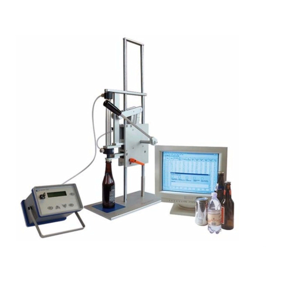
10 of 90 System Description - 3625 Package Analyzer 1.2 System Layout Fig 1-1: System Layout ORBISPHERE Operator Manual... -
Page 17: Package Positioning Systems
3625 Package Analyzer - System Description 11 of 90 1.3 Package Positioning Systems Holding plate for cans and glass bottles Holding clamp for PET bottle neck, with (swivel 90° to accommodate cans or a positioning groove (level of cap top) bottle). -
Page 18: Package Piercer Components
12 of 90 System Description - 3625 Package Analyzer 1.4 Package Piercer Components Components identification 1) Sampling tube insertion device and handles 2) Sampling tube adjustable lower stop 3) Analyzer manifold 4) Two step device (left side) for cans analyze, with release spacer 5) Piercing knife, metal or plastic type 6) Package positioning system (cans, glass, PET bottles) 7) Flow meter to regulate product flow past sensors... -
Page 19: Package Piercer Manual Operation Sequence
3625 Package Analyzer - System Description 13 of 90 1.4.1 Package Piercer Manual Operation Sequence According to instructions given on instrument display and PC: • Install a package in position • Pierce the package • Lower the sampling tube (only when asked !) •... -
Page 20: Main Menu
14 of 90 System Description - 3625 Package Analyzer 1.5.3 Main Menu Main menu is reached by pressing ESC as many times as needed: • MEASURE: Measurement • OPTIONS: Set up the instrument • CALIBRATE: Calibration procedures 1.5.4 Entering Values When entering numbers, several digits are displayed. -
Page 21: Installation
Your Beverage Package Analyzer includes the components listed in the Introduction section of this manual. Hach Ultra recommends installing the Beverage Package Analyzer on a laboratory table. Place it on a clean flat area, close to water and drain location, such as a sink. Locate the instrument convenient to the power source, the piercer and sensor connectors, and the PC running the OrbiPack software. -
Page 22: Measuring Instrument
16 of 90 Installation - 3625 Package Analyzer 2.2 Measuring Instrument The 3625 measuring instrument controls the measurement sequence of the Package Analyzer. It computes data and communicates results to the PC. 2.3 Package Piercer Installation The piercer operates under control of the 3625 instrument. The piercer is connected to the measuring instrument, the sensors, and the forcing gas supplies. - Page 23 See service instructions in sensor’s Maintenance manual. If you are not familiar with Orbisphere sensor servicing, your Hach Ultra representative will be glad to assist you. Once serviced, install the O sensor into the lower flow chamber.
-
Page 24: Purge And Forcing Gas Supply
18 of 90 Installation - 3625 Package Analyzer 2.3.2 Purge and Forcing Gas Supply The thermal conductivity sensor must have a supply of purge gas running before operating the system. Purge and forcing gas are the same gas. Connect the main inlet port of the piercer to the supply line. -
Page 25: Instrument Back Panel Connections
3625 Package Analyzer - Installation 19 of 90 2.3.3 Instrument Back Panel Connections Personal Computer (PC) Connect, using the RS 232 "serial" cable, the 6 pin socket on rear panel of the instrument to the RS- 232 port on the PC operating the OrbiPack software. -
Page 26: Liquid And Pneumatic Connections
20 of 90 Installation - 3625 Package Analyzer 2.3.4 Liquid and Pneumatic Connections Connect all components according to diagram below. ORBISPHERE Operator Manual... -
Page 27: Pc Software Installation
3625 Package Analyzer - Installation 21 of 90 2.4 PC Software Installation Note: Before installing, be sure to remove any previous versions of the software from your computer using the standard Add or Remove Programs option available from the Windows Control Panel. This will remove the software but leave all measurement files intact. -
Page 28: Installation Completion Check List
22 of 90 Installation - 3625 Package Analyzer • Click Finish to complete the installation. • The OrbiPack program icon will be installed on the desktop as part of the installation. Note: If you intend to use the inter-process communication option (see “Communication”... -
Page 29: Orbipack Pc Software
3625 Package Analyzer - OrbiPack PC Software 23 of 90 OrbiPack PC Software The Package Analyzer system cannot function without the OrbiPack software. Before attempting any measurements with the analyzer, ensure that: • An RS232 cable connects the PC to the instrument •... -
Page 30: Getting Help
24 of 90 OrbiPack PC Software - 3625 Package Analyzer 3.1.2 Getting Help A sophisticated on-line help system is available with the software. This manual gives an overview of the most important features of the software. For detailed and in-depth information of any screen or its contents, select the Help button associated with that screen. -
Page 31: Measurement Data Display
3625 Package Analyzer - OrbiPack PC Software 25 of 90 3.1.4 Measurement Data Display The illustration below is an example of the measurement display (the data and column definitions displayed are an example only). The display is user definable to meet different customer requirements. -
Page 32: Warning Messages
26 of 90 OrbiPack PC Software - 3625 Package Analyzer 3.1.6 Warning Messages During measurements, warning messages may pop up informing the user of potential problems with the measurement. The error will point the user to a table for more information. For example See table ID 09 as illustrated in the illustration below left. -
Page 33: Toolbar Shortcuts
3625 Package Analyzer - OrbiPack PC Software 27 of 90 3.1.8 Toolbar Shortcuts A number of shortcuts to menu options are available from the toolbar. In order from left to right in the illustration below: • Start a new measurement run •... -
Page 34: Package Menu
28 of 90 OrbiPack PC Software - 3625 Package Analyzer 3.3 Package Menu 3.3.1 Setup 3.3.1.1 Package Characteristics Enter the data corresponding to the package to be tested. Up to 500 different package specifications can be saved. Select the package to define from the drop-down list. The current settings for that package will be displayed: •... - Page 35 3625 Package Analyzer - OrbiPack PC Software 29 of 90 Alarms Alarm limits can be set on all measured and computed values. The example screen shot below shows all the values against which alarm limits can be set. The limits illustrated (MAX of 100 and MIN of 0) are the standard default values.
-
Page 36: Selection
30 of 90 OrbiPack PC Software - 3625 Package Analyzer Offsets Three of the measured values sent to the PC from the 3625 instrument can be modified. The offset value is used as a multiplication factor against the measured value received from the 3625 instrument (e.g. -
Page 37: Delete
3625 Package Analyzer - OrbiPack PC Software 31 of 90 3.4 Table Menu All the options available under this menu apply to the measurement lines (table data) displayed on the PC screen. 3.4.1 Delete Select one or more measurement lines to delete, then select Delete from the Table menu. - Page 38 32 of 90 OrbiPack PC Software - 3625 Package Analyzer 3.4.6 Table Settings This password protected option allows the user to define the parameters for the tabular measurement display on the PC. The dialog box contains six tabs that set the display parameters. Select each in turn to define what data to display, the data format, and the measurement units (screen illustrated above).
-
Page 39: Resize Rows
3625 Package Analyzer - OrbiPack PC Software 33 of 90 3.4.7 Resize Rows Select one, several or all rows, and then use this option to resize the selected rows to fit the cell contents. Note: You may also resize a row manually with the mouse by dragging the bottom border of the row header. -
Page 40: Diagnostics
34 of 90 OrbiPack PC Software - 3625 Package Analyzer 3.5.2 Diagnostics Displays the data exchanged on the serial link between the 3625 instrument and the OrbiPack program, while the data is being sent or received. Use the File menu option to save the diagnostic data in a text file or exit the window. The Edit menu option allows the user to copy, clear, or select the diagnostic data. - Page 41 3625 Package Analyzer - OrbiPack PC Software 35 of 90 • Login window - If this box is not checked, then no username or password is requested at login or when a new measurement run is selected. • Auto log off - If this box is checked, and if there is no access to the software after the time elapsed in the Log off inactivity time box has expired, no measurements will be allowed.
- Page 42 36 of 90 OrbiPack PC Software - 3625 Package Analyzer • CO2 measurement - Activate if the CO sensor result is greater than the calculated pressure-temperature CO result by a specified percentage. This limit is selectable in the % between measured and calculated CO concentration edit box.
- Page 43 3625 Package Analyzer - OrbiPack PC Software 37 of 90 Communication The software allows for communication with other control and management systems such as SCADA and LIMS, etc. OPC is used as the inter-process communication solution. The communication option is used to define the necessary parameters. If using the OPC inter-process communication solution, you must have the appropriate communications software installed on your PC (see “PC Software Installation”...
-
Page 44: Factory Settings
“OrbiPack Startup” on page 23). 3.5.5 Factory Settings This option requires a special password that is only available to qualified Hach Ultra service technicians. 3.5.6 Can Counter Reset This password protected option resets the can counter to zero. The counter is displayed in the status bar at the bottom of the screen and shows the total number of completed measurements. -
Page 45: User Management
3625 Package Analyzer - OrbiPack PC Software 39 of 90 The following table lists the operations allowed for the different access levels: Table 3-1: Security Access Levels Operation Guest Operator Supervisor Factory (no password) Read measured data Calibration Delete measured data Comments addition Package set-up Data table settings... -
Page 46: View Menu
40 of 90 OrbiPack PC Software - 3625 Package Analyzer 3.6 View Menu Use the view menu to hide or display: • The Toolbar at the top of the screen • The Status Bar at the bottom of the screen •... -
Page 47: Automatic Analysis Sequence
3625 Package Analyzer - Automatic Analysis Sequence 41 of 90 Automatic Analysis Sequence This section describes the sequence of actions that the Beverage Package Analyzer automatically performs during the analysis of a sample package (operator actions are indicated by the sign "=>"). A process drawing shows valves activated with gas and liquid path. -
Page 48: Headspace (Hs) Measurement
42 of 90 Automatic Analysis Sequence - 3625 Package Analyzer => Lower the piercing lever and pierce the package. Once the package is pierced, the pressure change gives a signal to start the analysis sequence. The instrument checks the package specifications, as entered in the "Package Selection"... - Page 49 3625 Package Analyzer - Automatic Analysis Sequence 43 of 90 Note: If the pressure exceeds the "safe limit" for this package type, or is insufficient to lift the liquid to the sensors (at least 0.5 bar greater than package pressure is required), the instrument displays a Too high or Too low error message, and the measurement sequence stops.
-
Page 50: Product Sampling And Analysis
44 of 90 Automatic Analysis Sequence - 3625 Package Analyzer 4.3 Product Sampling and Analysis => Lower the piercing lever and sampling tube. Lowering the sampling tube all the way triggers the sampling process. Forcing gas is sent through the sampling tube into the package. The forcing gas applies a down force to the product, pushing it through the sampling tube into the flow chambers. -
Page 51: Results Calculation And Transfer
3625 Package Analyzer - Automatic Analysis Sequence 45 of 90 Dissolved gas analysis The package content is pushed past the sensors. The next two displays indicate the results of gas concentration measurement. Note: On the CO analyzer, the O and CO concentrations are obtained from the sensors, while the N concentration is computed by the software. - Page 52 46 of 90 Automatic Analysis Sequence - 3625 Package Analyzer ORBISPHERE Operator Manual...
-
Page 53: Operating Instructions
3625 Package Analyzer - Operating Instructions 47 of 90 Operating Instructions 5.1 Measurement Menu The flow chart below gives an overview of the MEASURE menu and sequence. ORBISPHERE Operator Manual... -
Page 54: Package Piercer Adjustments
48 of 90 Operating Instructions - 3625 Package Analyzer 5.2 Package Piercer Adjustments 5.2.1 Two Step Device for Cans Note: When testing other packages than cans, block the two step knob out, using the spacer provided. For analyzing cans’ headspace, the two step device must be used to limit the travel of the piercing knife. -
Page 55: Adjust The Sampling Tube Lower Stop
3625 Package Analyzer - Operating Instructions 49 of 90 PET holding clamp: Lower the assembly until the bottom of the PET bottle touches down the rubber mat, the neck being supported by the clamp. 5) Lock orange lever when height is correct for the package used. 6) Check that positioning plate clears the package when the piercing lever is tilted backward (away from the operator), allowing easy substitution of packages. -
Page 56: Measurement Process
Note: It is recommended to perform the package analysis with packages at room temperature. Contact your Hach Ultra agent for measuring cold packages. When a series of cold packages follows a series of warm packages (or the opposite), the sensors will measure an evolution in temperature, until thermal equalization is reached. -
Page 57: Pierce The Package
3625 Package Analyzer - Operating Instructions 51 of 90 Note: During analysis, any pressure leak past rubber seal will alter results. If a leak is noticed and rubber seal is in good condition, try another position on the package top surface, where sealing can be complete. -
Page 58: Daily Cleaning (User Maintenance)
52 of 90 Operating Instructions - 3625 Package Analyzer CAUTION: Do not pull on cables and connections. This could damage the equipment. A position switch sends a signal saying that the tube is up. The instrument will not continue until such signal is received. Note: Once the piercing lever is up, forcing gas is briefly sent through the manifold to purge liquid out. - Page 59 3625 Package Analyzer - Operating Instructions 53 of 90 Note: Check that the small O-ring at the bottom of the flow chamber is present during removal and installation of the sensor, as it may stick to the sensor head and fall. Optional Purge Backup Unit Using the optional purge backup unit allows for switching off the instrument, still having the purge gas system running.
- Page 60 54 of 90 Operating Instructions - 3625 Package Analyzer ORBISPHERE Operator Manual...
-
Page 61: Options
3625 Package Analyzer - Options 55 of 90 Options The flow chart below gives an overview of the OPTIONS menu and sequence. Note: Always note on the test report the set values, as entered in the instrument, for traceability. ORBISPHERE Operator Manual... -
Page 62: Membrane Selection
56 of 90 Options - 3625 Package Analyzer 6.1 Membrane Selection Note: The selection of a membrane is a compromise between sensor services frequency (calibration, maintenance) and sensor sensitivity. It is also dependent of plant conditions (frequency of analysis, O level being measured). -
Page 63: Sampling System Purge
= 2.5 V2200 < V3 < 2800 [mV] for the N sensor If not within tolerance, contact your Hach Ultra representative. 6.4 Sampling System Purge This command opens the purge gas to the beverage sampling system. This is used to flush and dry the system during daily maintenance. -
Page 64: Oxygen Factor Correction
58 of 90 Options - 3625 Package Analyzer Procedure • ESC displays main menu • select OPTIONS; ENTER • select SERIAL OUTPUT; ENTER • select DIAGNOSTIC; ENTER • select CORRECTIONS; ENTER • select HUMIDITY; ENTER • select CALIBRATE; ENTER • Wait for stabilization of slope value. •... -
Page 65: Temperature Correction
3625 Package Analyzer - Options 59 of 90 • Check slope value on the OrbiPack Diagnostic view window. • Wait for stabilization of value (-15 [mV/sec] ± 10). • When value is stable, press ENTER to save the new oxygen correction factor. 6.5.3 Temperature Correction A significant change in the sample temperature influences the N sensor reading. -
Page 66: Oxygen Stability
60 of 90 Options - 3625 Package Analyzer • OPEN indicates that the tube is all the way up. • CLOSED indicates that the tube has been lowered. Pressure Forcing gas pressure check. Select PRESSURE. The instrument opens valves A and B, and closes valve C, and displays the forcing gas pressure P3 for 2 seconds. -
Page 67: Calibrations
3625 Package Analyzer - Calibrations 61 of 90 Calibrations The flow chart below gives an overview of the CALIBRATE menu and sequence. ORBISPHERE Operator Manual... -
Page 68: Planning Sensor Calibrations
62 of 90 Calibrations - 3625 Package Analyzer 7.1 Planning Sensor Calibrations This table shows recommended sensor calibration intervals for an average of 500 package analyses per week. This proposed schedule should be modified according to operating conditions. Sensor calibration Interval Notes PT 1000 temperature sensor... -
Page 69: Tools Needed
3625 Package Analyzer - Calibrations 63 of 90 7.1.2 Tools Needed • Sensor storage cap (sensor’s head plastic cover) • Certified barometer with a precision of ± 3 mbar • Certified pressure gauge - range: 0 - 5 bar - precision: ± 5 mbar •... -
Page 70: Barometric (Internal) Pressure Sensor Calibration
64 of 90 Calibrations - 3625 Package Analyzer 7.3 Barometric (internal) Pressure Sensor Calibration • ESC displays the main menu • select CALIBRATE; ENTER • select BAROM. PRESSURE; ENTER The instrument displays current barometric pressure reading. Measure barometric pressure using a certified barometer in the location where the measuring instrument is used. -
Page 71: One Point Calibration
3625 Package Analyzer - Calibrations 65 of 90 • Open forcing gas supply • enter the pressure value in bar, as read on the certified pressure gauge, plus barometric pressure (4 bar + 1.013 bar, in this example); ENTER • move decimal point ENTER 7.4.2 One Point Calibration The one point calibration starts with the following screen. -
Page 72: Thermal Conductivity Co Sensor Calibration
66 of 90 Calibrations - 3625 Package Analyzer Procedure • On the instrument, pressing ESC displays the main menu. • select CALIBRATE; ENTER • select O2 IN AIR; ENTER • Wait 5 minutes until the values read on the instrument display are stable. •... -
Page 73: Fraction Calibration Method
3625 Package Analyzer - Calibrations 67 of 90 7.6.1 Fraction Calibration Method Using the external calibration flow chamber accessory, the sensor is exposed to a known composition of CO (or N ) at atmospheric pressure. Note: Make sure the flow chamber is absolutely dry inside and out before use. Preparation •... -
Page 74: Partial Pressure Calibration
68 of 90 Calibrations - 3625 Package Analyzer After the third calibration cycle, the variation in sensitivity of the sensor is displayed as a percentage of the last calibration. Note: If the 3 calibration cycles show a variation over 1%, the 3 cycles are restarted. The instrument displays RECAL ERR XX% until the 3 cycles are within range. -
Page 75: Calibration Kit
3625 Package Analyzer - Calibrations 69 of 90 • enter the absolute pressure of CO (or N ) in the calibration gas, plus barometric pressure (4 bar + 1.013 bar, in this example); ENTER • move decimal point; ENTER The instrument will follow the same procedure as detailed in previous section (fraction calibration). -
Page 76: Dissolved Calibration With Reference Sample
70 of 90 Calibrations - 3625 Package Analyzer 7.6.4 Dissolved Calibration with Reference Sample In this method a beverage sample containing a known CO concentration is used. The system checks for 3 measurement cycles (20 sec. each) within a range of 1%. The reference value is introduced at the end of the procedure as the operator needs to know the liquid temperature of the reference being used, which will be shown by the analyzer. -
Page 77: Maintenance
3625 Package Analyzer - Maintenance 71 of 90 Maintenance Wear on the membrane and chemical reactions within the gas sensors requires that the sensors be serviced regularly to restore original sensitivity. A clear sign that a sensor maintenance is required is when measurements are noticeably less stable than usual, and when a calibration does not improve the situation. -
Page 78: Pressure Regulator
72 of 90 Maintenance - 3625 Package Analyzer 8.2 Pressure Regulator Drain the condensate periodically. Unscrew the drain at bottom of bowl. If filter is dirty: • Turn off the gas supply. • Unscrew the bowl by hand. • Unscrew the black disc at the bottom. •... -
Page 79: Sampling Tube Maintenance
3625 Package Analyzer - Maintenance 73 of 90 8.4 Sampling Tube Maintenance The sampling tube and sliding piece are sensitive items. Avoid scratching tube surface, as this will damage the rubber seals. Wipe tube daily with a cloth impregnated with Monolykote®... -
Page 80: Servicing The Manifold
74 of 90 Maintenance - 3625 Package Analyzer 8.6 Servicing the Manifold Whenever it is suspected that some product may have entered the manifold, manifold and electro valves require cleaning and testing. Product seen in the transparent lines connected to the manifold means that electro valves inside may be leaking. Manifold reservoir •... -
Page 81: Instrument Service
3625 Package Analyzer - Maintenance 75 of 90 Note: During disassembly, carefully note location and orientation of components. For proper operation, tightness of the complete assembly is mandatory. 8.7 Instrument Service To open the instrument, disconnect the AC power, remove the front-panel key, and place the instrument face down. - Page 82 76 of 90 Maintenance - 3625 Package Analyzer ORBISPHERE Operator Manual...
-
Page 83: Troubleshooting
3625 Package Analyzer - Troubleshooting 77 of 90 Troubleshooting 9.1 Control Valves Check Routine The measuring instrument Check Routine function allows checking forcing gas pressure and control valves operation. Select CHECK ROUTINE from the OPTIONS menu, then select ABC check or D check. The measuring instrument will run the corresponding test. -
Page 84: Orbipack Software Error Messages
78 of 90 Troubleshooting - 3625 Package Analyzer 9.2 OrbiPack Software Error Messages See also “Table Settings” on page 32 for details on how to view the error flags on the measurement display. The error flag is a 32 digit field filled with either a zero or one (0 = OK and 1 = error). On completion of a measurement, check the status of the error flag. -
Page 85: Measuring Instrument Error Messages
Recommended action Restore purge gas to specifications Purge gas failure Perform the Continuous Purge test (Options menu) Damaged sensing element Return sensor to Hach Ultra Check purge gas Purge voltage drifting Perform the Continuous Purge test (Options menu) Reduce gas permeation... -
Page 86: Troubleshooting Guide
80 of 90 Troubleshooting - 3625 Package Analyzer 9.4 Troubleshooting Guide The following table lists possible problems, causes, and proposed solutions. Symptom Possible cause Correction Sensor Check connections. Instrument No power. Check instrument voltage label on the does not start. Incorrect voltage. -
Page 87: Diagnostic Information On Pc
3625 Package Analyzer - Troubleshooting 81 of 90 9.5 Diagnostic Information on PC 9.5.1 Diagnostic Information During the Measure Procedure Slope Temp Part. St-Dv T corr press 1000 [mV] [mV] [mV/s] [°C] [bar] [mv/s] [°C] [°C] [mv/s] #0 -256.8 -301.2 -3.170 24.53 -0.2825 0.000... -
Page 88: Diagnostic Information During The Calibrate Procedure
82 of 90 Troubleshooting - 3625 Package Analyzer 9.5.2 Diagnostic Information During the Calibrate Procedure % last Slope Temp corr T corr [mV] [mV] [mV/s] [°C] corr 92.3 3990.5 3985.3 -0.516 12.93 -0.525 -0.000 -0.006 0.0002 93.4 3992.7 3987.5 -0.520 12.92 -0.525 -0.000... -
Page 89: Spare Parts
3625 Package Analyzer - Spare Parts 83 of 90 10 Spare Parts 10.1 Piercer Parts Part N° Description 2952A Tefzel membranes for electrochemical sensors Ø 32 mm 25 µm. (25 piece set) 2956A PFA membranes for electrochemical sensors Ø 32 mm, 25 µm. (25 piece set) 28078A Filters for filter assembly (gas filters- 5 piece set) 28114... -
Page 90: Sensor Specific Parts
84 of 90 Spare Parts - 3625 Package Analyzer Part N° Description 32910 Package piercing seal to package (10 piece set) 32912 O-ring set for micro-volume flow chambers ( 5 inner + 5 outer o-ring set) 32914 In line particle filter assembly, complete 32915 O-ring for in line particle filter (10 piece set) 32920... -
Page 91: Appendix A: Glossary
3625 Package Analyzer - Glossary 85 of 90 Appendix A: Glossary A.1 Common Units Table A-1: Common Units Unit Meaning percentage, by weight % vbar percentage per volume, barometric pressure referenced % vext percentage per volume, sample pressure compensated cc/kg cubic centimeters per kilogram g/kg grams per kilogram... - Page 92 86 of 90 Glossary - 3625 Package Analyzer ORBISPHERE Operator Manual...
- Page 93 3625 Package Analyzer - Annex 87 of 90 Annex Tables and Illustrations Fig. 1-1 System Layout...................10 Table 2-1 Supplies.....................15 Table 3-1 Security Access Levels..............39 Table 7-1 Electrochemical Sensor Calibration Methods........65 Table 7-2 Thermal Conductivity Sensor Calibration Methods ......66 Table 7-3 Calibration Kit Part Numbers .............69 Table 8-1 Recommended Maintenance Schedule..........71 Table 9-1 Electro Valve A, B, and C Check............77 Table 9-2 Electro Valve D Check (pilots the pneumatic valves D’...
- Page 94 88 of 90 Annex - 3625 Package Analyzer ORBISPHERE Operator Manual...
- Page 95 3625 Package Analyzer - User Notes 89 of 90 User Notes ORBISPHERE Operator Manual...
Need help?
Do you have a question about the ORBISPHERE 3625 and is the answer not in the manual?
Questions and answers