Table of Contents
Advertisement
Quick Links
Advertisement
Table of Contents

Related Manuals for Void Inca 500


Summary of Contents for Void Inca 500
- Page 1 Inca 500 Pro audio you can depend on U S E R G U I D E V 1 . 0...
- Page 2 For the latest online version, visit: www.voidacoustics.com Void Acoustics and the Void logo are registered trademarks of Void Acoustics Research Ltd. in the United Kingdom, USA and other countries; all other Void trademarks are the property of Void Acoustics Research Ltd.
-
Page 3: Table Of Contents
Input Tab 5.3.2 Zone Tab 5.3.3 Output Tab 5.3.4 Speaker Preset Menu Parameters 5.3.5 Settings Tab Setup and Signal Routing 5.4.1 Input Setup 5.4.2 Zone Setup & Routing GPIO Setup and Connection UG10637-1.0 - Inca 500 User Guide V1.0 Page 3... -
Page 4: Safety And Regulations
18. The appliance coupler, or the AC Mains plug, is the AC mains reprocessor, or by returning it to Void Acoustics Research Ltd for disconnect device and shall remain readily accessible after reprocessing. - Page 5 0°C to 40°C. These amplifiers are not intended for use above 2000 meters above sea level. Amplifiers installation or operated in environments outside these limits may invalidate support, warranty or guarantees of performance. UG10637-1.0 - Inca 500 User Guide V1.0 Page 5...
-
Page 6: Unpacking And Checking
Carton Contents Inca 500 amplifiers are shipped in a cardboard carton containing the amplifier unit, a mains cable appropriate for the sales territory, an accessory pack, and a document pack. The full contents is listed below. -
Page 7: About
In buying this product, you are now part of the Void family and we hope using it brings you years of satisfaction. This guide will help you both use this product safely and ensure it performs to its full capability. -
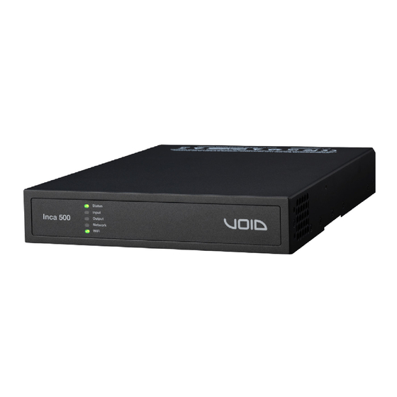
Page 8: Connections
RJ45 socket Ethernet network connection options are also provided. Inca 500 amplifiers have no mains power switch and are operational as soon as mains power is connected via the IEC 60320 mains socket. -
Page 9: Installation
Multiple Inca 500 amplifiers can also be mechanically connected using accessory connecting plates. Figure 4.3 illustrates the use of connecting plates. Figure 4.3: 2 x Inca 500 with Connection Plate. 2 positions UG10637-1.0 - Inca 500 User Guide V1.0 Page 9... -
Page 10: Free Standing
Wall and desk mounting is 2 x M3 x 6 countersunk illustrated in figure 4.4 and 4.5. Figure 4.4: Inca 500 with desk/wall Mounting Plate and adhesive feet. 2 positions and 4 positions. It is important in any free standing installation that airflow through the amplifier’s side... -
Page 11: Configurations
Note: Inca 500 amplifiers can be configured to use DHCP for network connection if required. However, if an Inca 500 amplifier using DHCP is power cycled, it is possible that the TCP/IP network router will assign it a different IP address, leaving its configuration page inaccessible via the previous address. -
Page 12: Wireless (Wifi) Network Connection
To connect an Inca 500 amplifier to a TCP/IP network using a wireless connection (WiFi) follow the steps below. 1. With the Inca 500 amplifier connected to mains power, wait for the front panel WiFi indicator to illuminate green. 2. Use a mobile, laptop or desktop device to search for available WiFi networks. Connect to, Inca 500 (product serial number)’... -
Page 13: Configuration Menus
Opening a web browser that is network connected to an Inca 500 amplifier initially displays the Inca 500 Web App Dashboard illustrated in figure 5.1. The Dashboard is the ‘home’ page from which all other configuration options can be accessed. -
Page 14: Zone Tab
The default compression parameters are appropriate for most installations. Select zone Zone name - type to edit Select mono or stereo Adjust zone volume Select input Figure 5.3: Zone Tab display UG10637-1.0 - Inca 500 User Guide V1.0 Page 14... -
Page 15: Output Tab
Equalizer settings configured for one amplifier output can be copied and applied to other outputs. Select output Output name - type to edit Select zone Figure 5.4: Output Tab display UG10637-1.0 - Inca 500 User Guide V1.0 Page 15... - Page 16 2. Select the appropriate ‘.zcp’ format speaker preset data file to import. The preset data will be applied to the selected amplifier output as soon as the file import is complete. Figure 5.5: Speaker Preset Parameters Figure 5.6: Speaker Preset import file selection UG10637-1.0 - Inca 500 User Guide V1.0 Page 16...
-
Page 17: Speaker Preset Menu Parameters
Begin with the default filter setting of 70Hz. If low frequency distortion is still audible, increase the frequency setting one step at a time until the distortion is no longer audible. UG10637-1.0 - Inca 500 User Guide V1.0 Page 17... -
Page 18: Settings Tab
5.4 Setup and Signal Routing Thanks to their network based configuration features, Inca 500 amplifiers offer considerable versatility in terms of sources, signal routing, installation zones and output modes. Inputs can be freely assigned to installation zones, and those zones assigned freely to the available amplifier outputs in either Lo-Z or Hi-Z modes. -
Page 19: Input Setup
• 1 x mono Hi-Z zone + 2 x mono Lo-Z zones Note: When configured in Hi-Z mode Inca 500 amplifiers operate in ‘bridged’ mode where the output of two channels is combined. This means that the number of output channels available in Hi-Z mode is half that available in Lo-Z mode . - Page 20 Polarity Limiter Gain Adjustment Alignment Sensitivity Output 4 Analog 4 Input Gain SPDIF (stereo) Pink Noise Gain SPDIF Out (stereo). Zones A (left) and B (right) Figure 5.8: Signal Flow Schematic UG10637-1.0 - Inca 500 User Guide V1.0 Page 20...
-
Page 21: Gpio Setup And Connection
5 Configurations 5.5 GPIO Setup and Connection Inca 500 amplifiers provide a GPIO socket that enables remote control of volume, standby, mute and trigger functions. The GPIO connector pin functions are described in the GPIO Settings menu illustrated in figure 5.12. -
Page 22: Connections
Analog Inputs Inca 500 analog inputs are of line level format with a default input sensitivity of +4dBu (full output voltage swing/sensitivity) in all output modes. Input signal levels up to +24dBu can be handled without input clipping. Input sensitivity options can be set via the amplifier net- work interface. -
Page 23: Speaker Cable Gauge
Figure 6.1: Inca 500 rear panel connections 6.4 Speaker Cable Gauge Cable Gauge Table Inca 500 speaker connection cable gauge should be chosen appropriately to reflect the Lo-Z installations. 4Ω & 8Ω loads type of installation. The adjacent Cable Cross... -
Page 24: Network Connections
Inca 500 amplifiers are TCP/IP network connected devices that are configured via a web page based interface. Wired (Ethernet) and wireless (WiFi) connection options are available. Connecting Inca 500 amplifiers to a TCP/IP network is described in Section 5 of this manual. - Page 25 WIRING text, intended to alert users to the risk of hazardous voltages. Output connectors that could pose a risk are marked with the exclamation point. Do not touch the output terminals while the amplifier is switched on. Make all connections with the amplifier switched off. UG10637-1.0 - Inca 500 User Guide V1.0 Page 25...
-
Page 26: Operations
Audio will be heard from any connected speakers. Note: Inca 500 amplifiers will not switch on from Standby Mode unless an input signal is present, a network ‘ON’ command is received, or an external standby switch (or 12V trigger) is operated. -
Page 27: Automatic Power Sharing
7.3 Default Reset Inca 500 amplifiers can be returned to their default settings via either the Control Web App Settings Tab or the hardware reset pinhole button. The reset pin-hole button is located on the underside panel of the amplifier. With the amplifier connected to mains power, use an appropriate tool to press and hold the reset pinhole button for a few seconds. -
Page 28: Specifications
2x Rack ears 1x ½ rack plate extension Accessories 2x ½ rack mounting 2x Rear supports Power Ratings 1% THD @ 120Vac and 230Vac *100V line mode is @ -1dB (≈ 90 V) UG10637-1.0 - Inca 500 User Guide V1.0 Page 28... - Page 29 H E A D O F F I C E Void Acoustics Research Ltd, Unit 15, Dawkins Road Industrial Estate, Poole, Dorset, BH15 4JY United Kingdom Call: +44(0) 1202 666006 Email: info@voidacoustics.com voidacoustics.com Void Acoustics Research Limited is a company registered in England and Wales registration number 07533536...
Need help?
Do you have a question about the Inca 500 and is the answer not in the manual?
Questions and answers