Advertisement
Quick Links
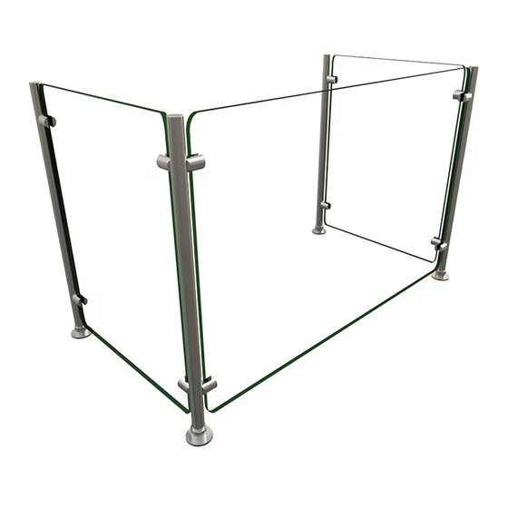
Flav-R-Shield™
Full Service Sneeze Guards
Model EP5
Model EP5 Full Service Sneeze Guards are available in ten
widths ranging from 36"–144" (914–3658 mm), with a common
height of 25" (635 mm) and a common depth of 18" (457 mm).
For additional information regarding Model EP-5 sneeze guards,
scan the QR Code below:
https://www.hatcocorp.com/en/equipment/sneeze-guard-equipment/
full-service/flav-r-shield-full-service-pass-over-sneeze-guard-ep5
Important Safety Information
To avoid serious injury and damage to equipment or property, read
the following safety information before installing this equipment.
Do not attempt to assemble and install sneeze guards alone.
Installation of sneeze guards requires two or more people,
dependent upon unit.
Always wear proper protective eye wear when handling glass
sneeze guards.
Never spray cleaners directly onto sneeze guard surfaces.
Spray cleaner into non-abrasive cloth, and then wipe down
surfaces.
Use non-abrasive cleaners and cloths only. Abrasive cleaners
and cloths could scratch finish of unit, marring its appearance
and making it susceptible to soil accumulation. Use of abrasive
materials will void warranty.
Assembly and Installation
1. Unpack all components. Verify that the appropriate number of
the items below are present.
• Face Panel, 1/4" Glass
• End Panel, 1/4" Glass
• Post Assembly, 1" Stainless Steel
• Hardware Packet (includes hex wrench for set screws)
2. Remove the Mounting Flanges from each Post Assembly.
a. Slide the Flange Cover up and off of the flange.
b. Using the included hex wrench, loosen the set screw on the
flange.
c. Slide the flange off of the Post Assembly.
IMPORTANT NOTE
Sneeze guards that consist of multiple bays require careful
measurement before installation of the Mounting Flanges.
3. Install the Mounting Flanges to the mounting surface.
a. Refer to the "Model EP5 Standard Sizes" chart and illustration
below to determine the location of the flanges. For multiple
bay installations, refer to "Width per Bay" column in the chart.
b. Position the flanges in the appropriate locations, and mark
the screw hole locations. IMPORTANT! Measure carefully,
and make sure the flanges remain square to each other as
well as the installation location.
c. Pre-drill the screw holes in the mounting surface.
d. Install the flanges using the appropriate, #8 countersunk-
style fasteners for the mounting surface.
© 2022 Hatco Corporation
INSTALLATION GUIDE
Model EP5 Standard Sizes
Total Width (A)
(post center to
Item Number
center)
EP5-036
(914 mm)
EP5-048
(1219 mm)
EP5-060
(1524 mm)
EP5-072
(1829 mm)
EP5-084
(2134 mm)
EP5-096
(2438 mm)
108"
EP5-108
(2743 mm)
120"
EP5-120
(3048 mm)
132"
EP5-132
(3353 mm)
144"
EP5-144
(3658 mm)
A
EP5-060 (2 Bay)
30"
NOTE: 18" End Panels meet NSF requirements.
4. Insert each Post Assembly into its corresponding Mounting
Flange. Make sure the posts are fully seated in the flanges.
5. Tighten the set screw on each Mounting Flange securely.
6. Slide each Flange Cover down onto its corresponding flange.
1
P/N 07.14.002.00-0822 [EP5_IG]
Number
Width per Bay
of
(post center to
Bays
center)
36"
1
(914 mm)
48"
2
(610 mm)
60"
2
(762 mm)
72"
2
(914 mm)
84"
2
(1067 mm)
96"
3
(813 mm)
3
(914 mm)
3
(1016 mm)
4
(838 mm)
4
(914 mm)
EP5-036 (1 Bay)
18"
30"
A
36"
24"
30"
36"
42"
32"
36"
40"
33"
36"
25"
continued...
Advertisement

Subscribe to Our Youtube Channel
Related Manuals for Hatco Flav-R-Shield EP5


Summary of Contents for Hatco Flav-R-Shield EP5
- Page 1 5. Tighten the set screw on each Mounting Flange securely. d. Install the flanges using the appropriate, #8 countersunk- style fasteners for the mounting surface. 6. Slide each Flange Cover down onto its corresponding flange. continued... © 2022 Hatco Corporation...
- Page 2 HATCO CORPORATION P.O. Box 340500 24 Hour 7 Day Parts and Service Milwaukee, WI 53234-0500 U.S.A. Assistance available in the United States 414-671-6350 and Canada by calling 414-671-6350. support@hatcocorp.com www.hatcocorp.com © 2022 Hatco Corporation...
Need help?
Do you have a question about the Flav-R-Shield EP5 and is the answer not in the manual?
Questions and answers