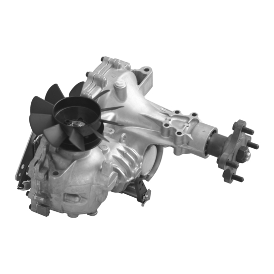
Hydro-Gear ZT-2800 Service And Repair Manual
Integrated zero-turn transaxle
Hide thumbs
Also See for ZT-2800:
- Service and repair manual (52 pages) ,
- Service and repair manual (52 pages)

Related Manuals for Hydro-Gear ZT-2800


Summary of Contents for Hydro-Gear ZT-2800
- Page 1 ZT-2800 /ZT-3100 /ZT-3200™ ® ® Integrated Zero-Turn Transaxle Service and Repair Manual BLN-52441 January 2023...
-
Page 2: Table Of Contents
Side Cover – Screw Tightening Sequence .. 42 Control Arm Assembly ........ 15 How To Use Service Schematic ....43 Parking Brake Adjustment ......16 ZT-2800 Exploded View & Parts List ..44-45 ® Parking Brake Assembly......17 ZT-3100 Exploded View &... -
Page 3: Foreword
Central Service Distributor, or call our Customer Service Depart- ment at (217) 728-2581. PRODUCT IDENTIFICATION The model and configuration of the ZT-2800, ZT-3100 and ZT-3200 can be determined from the label found on the transaxle. BOM Model Number 2D Q Code... -
Page 4: Description And Operation
® ® transaxle allows for easy oil maintenance. The Zero-Turn Transaxles. This manual includes ZT-2800 is designed for both charged and the general descriptions, hydraulic schematics, uncharged product versions. In the uncharged technical specifications, servicing and trouble- consumer vehicle drive, fluid passes through shooting procedures for both transaxles. -
Page 5: Hydraulic Schematic
Charge Relief Charge Pump Figure 2, Hydraulic Schematic With Charge Pump Vent Case Reservoir Input Shaft Bypass Motor Pump Motor Shaft System Check Valves Filter Figure 3, Hydraulic Schematic Without Charge Pump (ZT-2800) ZT-2800 ZT-2800 /ZT-3100 /ZT-3200 ® ® ®... -
Page 6: External Features
EXTERNAL FEATURES ZT-2800 /ZT-3100 /ZT-3200 ® ® Axle Shaft Main Housing Bypass Arm Control Arm — Top View — Drain Port Top Port Plug (For Horizontal Installation) Parking Brake Arm Side Cover — Inboard View — ZT-2800 /ZT-3100 /ZT-3200 ®... - Page 7 EXTERNAL FEATURES ZT-2800 /ZT-3100 /ZT-3200 ® ® Input Shaft Axle Shaft Oil Filter Expansion Port (For Horizontal Installation) — Outboard View—Left (Standard Control) — Fan and Pulley Kit Return To Neutral Assembly Charge Pump — Outboard View—Right (Return To Neutral Control) —...
-
Page 8: Technical Specifications
TECHNICAL SPECIFICATIONS ZT-2800 ® SPECIFICATIONS ZH/ZJ ZK/ZL Overall Transaxle 20.69:1 24.74:1 27.23:1 Reductions Pump Displacement 0.61 in /rev [10cc/rev] Motor Displacement 0.97 in /rev [16cc/rev] Filter Rating 25 Micron Nominal, 40 Micron Absolute Suction Filter Input Speeds Maximum Hi-Idle (No Load) 3000 rpm Non-Charge —... -
Page 9: Safety
Never allow untrained or unauthorized person- nel to service or repair the equipment. ZT-2800 ZT-2800 /ZT-3100 /ZT-3200 ® ®... -
Page 10: Troubleshooting
Brake Partially Engaged Disengage Brake, Replace Broken or Missing Brake Return Spring Tr a ns a xle Leaks Oil Damaged seals, housing, or gaskets Replace damaged components Air trapped in hydraulic system Purge hydraulic system, Page 12 ZT-2800 /ZT-3100 /ZT-3200 ® ®... -
Page 11: Service And Maintenance
1. Use of components for purpose of repair other Correct oil volume is determined by characters 7 and 13 of the model number. (Z*-****-X***-***X*) than Genuine Hydro-Gear parts must be pre au- thorized in writing by Hydro-Gear to be eligible for CHAR 7 CHAR 13 Oil Volume warranty consideration. -
Page 12: Filter And Filter Guard
(111) from inlet port and allow any remaining oil to drain from the transaxle. Inspection 1. Inspect all parts for excessive wear or dam- age. Replace if necessary. Units will have installed, the fitting (111) or the plug (5). Breather vent on units equipped with internal expansion tank. When refilling the transaxle with oil, remove the port plug (5), if installed, and plug (11). Fill until the oil reaches the lower lip of port (11) on side cover. Figure 4, Filter and Guard ZT-2800 /ZT-3100 /ZT-3200 ® ®... -
Page 13: Fluid Change Procedure
12. Continue to fill the transaxles through the expansion tank until the “Full Cold” line is reached on the Hydro-Gear ex- 2. Place an oil drain pan (12” or more diameter and 8 qt. pansion tank (refer to vehicle owner’s manual for specific capacity is optimal) beneath the oil filter. -
Page 14: Purging Procedures
Before starting, make sure the transaxle is at forward and reverse at normal speeds, then the proper oil level. If it is not, fill to the specifi- the transaxle is considered purged. cations outlined in this manual. ZT-2800 /ZT-3100 /ZT-3200 ® ®... -
Page 15: Return To Neutral Setting
2. Remove the Original Equipment Manufac- to Figure 7. turer’s (OEM’s) control linkage at the control arm. ROTATION "B" ROTATION "A" RTN Adjusting Screw Speed and Direction Control Arm Figure 7, Return to Neutral Setting ZT-2800 ZT-2800 /ZT-3100 /ZT-3200 ® ® ®... -
Page 16: Return To Neutral Assembly
The seal is not part of the RTN control arm kit (211), and cannot be serviced separately. Refer to “Seal Kit” in the Items List on pager 46. Inspection 1. Inspect all parts for excessive wear or dam- age. Replace if necessary. Refer to “Return to Neutral Setting” On Page 13. Figure 8, Return to Neutral Assembly ZT-2800 /ZT-3100 /ZT-3200 ® ®... -
Page 17: Control Arm Assembly
Refer to “Seal Kit” in the reassembling the unit. Items List on page 46. Inspection 1. Inspect all parts for excessive wear or dam- age. Replace if necessary. Figure 9, Control Arm Assembly ZT-2800 ZT-2800 /ZT-3100 /ZT-3200 ® ® ®... -
Page 18: Parking Brake Adjustment
ZT-2800 /ZT-3100 PARKING BRAKE ADJUSTMENT (Code 1 or 2) ® ® Only if Character #7 in the model number 4. While holding the parking brake handle code is 1 or 2. (102) firmly onto the splines, remove clip (103) from the shaft tip. -
Page 19: Parking Brake Assembly
ZT-2800 /ZT-3100 PARKING BRAKE ASSEMBLY (Code 1 or 2) ® ® Only if character #7 in the model number code is 1 or 2. Example: ZX-XXXX-1XXX-XXXX Refer to Figure 12 Inspection Disassembly 1. Inspect all parts for excessive wear or dam- 1. Mark the position of the cam stop retainer age. -
Page 20: Brake Arm Assembly
ZT-2800 /ZT-3100 /ZT-3200 BRAKE ARM ASSEMBLY ® ® (Code 3/5/6/7) Character #7 in the model number code is 3, 5, 6 or 7. Example: ZX-XXXX-3XXX-XXXX Refer to Figure 13 Inspection Disassembly 1. Inspect all parts for excessive wear or dam- 1. Mark the position of the brake arm (102) in age. -
Page 21: Parking Brake Assembly
ZT-2800 /ZT-3100 PARKING BRAKE ASSEMBLY ® ® Assembly (Code A) 1. Reassemble all parts in the reverse order Character #7 in the model number code is A. of disassembly. See page 22 for the torque Example: ZX-XXXX-AXXX-XXXX values of the brake yoke bolts (176 and 175). -
Page 22: Hub Removal
2. Remove the hex retaining nut (3/4-16) from the center of the axle hub and discard. 3. Back out the hub removal tool bolt with a 1-1/8” socket before installing the hub re- moval tool to the axle hub. ZT-2800 /ZT-3100 /ZT-3200 ® ®... -
Page 23: Tear Down And Reassembly
Hydro-Gear replacement parts of maintenance. Cleaning of all parts by us- found at www.hydro-gear.com or at your Hydro- ing a solvent wash and air drying is usually Gear Central Service Distributor. -
Page 24: Tools
80-120 lb-in (9.04 - 13.5 Nm) Brake Yoke Bolt Bolt, Hex Head w/ Patch 80-120 lb-in (9.04 -13.5 Nm) Brake Yoke Bolt As a general rule, use the low end of the torque spec on fasteners when reassembling the unit. ZT-2800 /ZT-3100 /ZT-3200 ® ®... -
Page 25: Transaxle Removal
2. When tightening the fasteners, refer to the summary of the assembly procedures, in the table on page 22 for the required torque order in which they should occur, is given on values. page 41. NOTE: As a general rule, use the low end of the torque specification on fasteners when reassembling the unit. Figure 16, Fan/Pulley Kit (207) Configuration “A” ZT-2800 /ZT-3100 /ZT-3200 ® ®... - Page 26 22 for the required torque table on page 22 for the required torque values. values. NOTE: As a general rule, use the low end of the torque specification on fasteners when reassembling the unit. Figure 18, Fan/Pulley Kit (207) Configuration “C” Figure 17, Fan/Pulley Kit (207) Configuration “B” ZT-2800 /ZT-3100 /ZT-3200 ® ®...
- Page 27 FAN AND PULLEY (Continued) Refer to Figure 19 Disassembly FAN AND PULLEY KIT (207) CONFIGURATION “D” (ZT-2800 /ZT-3100 ® ® 1. Remove the locknut (122), slotted washer (123), pulley (121), fan (120) and pulley disc (121) the from the input shaft. nspection 1. Check all components for excessive wear or damage.
-
Page 28: Side Cover
22 for the required torque ant from the main housing, place a protective values. cover over the internal parts of the transaxle; avoiding any debris from entering the hous- ing. Pry Point Locating pin Pry Point Locating pin Stuff a clean rag in the center section oil filter passage before scraping the sealant off the center section. This is to prevent any sealant from getting into the oil passage. Figure 20, Side Cover ZT-2800 /ZT-3100 /ZT-3200 ® ®... -
Page 29: Bull, Pinion And Reduction Gears
2. Separate the reduction gears and inspect the gears and jack shaft pin for excessive wear or damage. Replace if necessary. Motor Shaft (73) Figure 21, Bull, Reduction and Pinion Gear ZT-2800 /ZT-3100 /ZT-3200 ® ®... -
Page 30: Internal Expansion Tank (Iet)
Removal of the internal expansion tank (195) and the breather vent (194) is not neces- sary while performing service and repair to the unit. Breather Vent (194) Top Port Plug (5) Internal Expansion Tank (195) Figure 22, Internal Expansion Tank ZT-2800 /ZT-3100 /ZT-3200 ® ®... -
Page 31: Charge Pump
2. Align the mark on the charge pump cover, (from step 1, Disassembly), with the mark on the main housing. Charge Pump Cover Main Housing Squared Directional Mark Mark made before disassembly Figure 23a, Charge Pump Figure 23, Charge Pump Cover Orientation ZT-2800 /ZT-3100 /ZT-3200 ® ®... -
Page 32: Charge Pump Orientation
CHARGE PUMP ORIENTATION Z*-L***-****-**** Z*-K***-****-**** Z*-P***-****-**** Z*-N***-****-**** Z*-G***-****-**** Z*-H***-****-**** Figure 24, Charge Pump Orientation ZT-2800 /ZT-3100 /ZT-3200 ® ®... -
Page 33: Input Shaft
(using a neoprene of disassembly. head hammer) the shaft from the charge pump side of housing. Care should be taken not to damage the shaft or gerotor running surface. Remove the bearing from pump shaft only if worn or damaged. ZT-2800 /ZT-3100 /ZT-3200 ® ® Figure 25, Input Shaft ZT-2800 /ZT-3100 /ZT-3200 ®... -
Page 34: Bypass Arm
NOTE: It is not necessary to remove the clip retaining ring (31) from the bypass rod (32) unless it is damaged or worn. 5. Remove the lip seal (30) and discard. Inspection 1. Inspect the bypass rod (32) for wear or dam- age. Replace if necessary. NOTE: Take care to insure that the bypass rod is free of burrs that may cut the rubber lip seal. Figure 26, Bypass Arm ZT-2800 /ZT-3100 /ZT-3200 ® ®... -
Page 35: Swashplate
1. Inspect the swashplate (40) and thrust bearing assembly (65) for wear or damage. Replace if necessary. 2. Inspect pump block per detail (figure 28). Thick Race Toward Pistons Figure 28, Hydraulic Pump Components Figure 27, Swash Plate ZT-2800 /ZT-3100 /ZT-3200 ® ®... -
Page 36: Center Section
Replace if necessary. 3. Inspect for scratches on the machined sur- faces of the center section. 4. Inspect motor cylinder block assembly (34) per detail on page 37. Assembly Center Section Figure 29, Center Section ZT-2800 /ZT-3100 /ZT-3200 ® ®... -
Page 37: Brake Assembly
BRAKE ASSEMBLY (Code 1 or 2) (ZT-2800 /ZT-3100 ® ® Assembly Character #7 in the model number code = 1 or 2. 1. Install the new O-rings (10) onto the brake Example: ZX-XXXX-1XXX-XXXX (cam) shaft (101). NOTE: Apply a thin coating of oil to the O-rings Refer to Figure 30 before installing. Disassembly... - Page 38 Z * - (G, H, J) * * * - * (E-H, N-T) * * - * * * * Left Rot. B Z * - (K, L, M) * * * - * (E-H, N-T) * * - * * * * Figure 31, Brake Shaft Assembly Figure 32, Brake Pawl Orientation ZT-2800 /ZT-3100 /ZT-3200 ® ®...
-
Page 39: Center Section Kit
Figure 33, Center Section Kit (201) damage. Pay particular attention to the cen- ter section’s threaded ports and passages; there must be no lose particles or debris. Rubber Plug (16) NOTE: For non-charge ZT-2800 units without ® Solid “charge relief,” a rubber plug (16) will be present rather than connecting tubes (ref. -
Page 40: Check Plugs & Seals
Refer to pages 33 and 34. Figure 34, Plug Seal (26) Pistons Piston Seats Springs Cylinder Block Figure 35, Pump/Motor Cylinder Block Assembly ZT-2800 /ZT-3100 /ZT-3200 ® ®... -
Page 41: Axle Shaft
AXLE SHAFT (ZT-2800 /ZT-3100 ® ® Refer to Figure 36 Assembly Disassembly 1. Assemble items in reverse order of disas- 1. Remove all items beginning on page 14. sembly. 2. Remove the retaining ring (90). NOTE: To protect the lip seal from possible 3. - Page 42 6. Remove the axle shaft (94) in the direction of arrow. NOTE: To protect the lip seal from possible damage when installing into the bore 7. Remove the bearing (95). and over the axle shaft, apply a protec- NOTE: Remove the bearing from the axle shaft tive covering over the splines, sharp only if worn or damaged. corners and/or keyway of the axle shaft (e.g., cellophane, tape, etc.). Figure 37, Axle Assembly ZT-2800 /ZT-3100 /ZT-3200 ® ®...
-
Page 43: Assembly After Complete Tear Down
6. Install the reduction gears, pinion gear and 11. Perform the purge procedures listed on bull gear. See page 27. page 12. Sealant Path for Main Housing Sealant Path for Center Section Figure 38, Sealant Application Diagram ZT-2800 /ZT-3100 /ZT-3200 ® ®... -
Page 44: Side Cover - Screw Tightening Sequence
SIDE COVER – SCREW TIGHTENING SEQUENCE Starting with the number “1” screw location, tighten sequentially through to “16.” Torque each screw to 105 - 155 lb-in (11.87 - 17.52 Nm). NOTE: As a general rule, use the low end of the torque specification. Figure 39, Screw tightening sequence diagram ZT-2800 /ZT-3100 /ZT-3200 ® ®... -
Page 45: How To Use Service Schematic
In this example it will be “H”. Refer to the model number in step 2. 7. Since character number 2 is “H”, the part number for item 81 is 52148. ZT-2800 /ZT-3100 /ZT-3200 ®... -
Page 46: Zt-2800 ® Exploded View & Parts List
ZT-2800 /ZT-3100 /ZT-3200 TRANSAXLE EXPLODED VIEW ® ® ZT-2800 /ZT-3100 /ZT-3200 ® ®... - Page 47 ZT-2800 /ZT-3100 /ZT-3200 TRANSAXLE PARTS LIST ® ® Housing, Main Handle, Brake Cover, Side Clip, Retaining Plug 9/16-18 (Metal) Screw, Hex Flange Head 1/4-20 x .75 Screw, Hex head 1/4-20 x 1.25” Guard, Filter O-ring, -111,.103 x .424 Spacer Plug, 9/16-18 (Metal) Fitting, STR 9/16-18 SAE .5 BARB...
-
Page 48: Glossary Of Terms
Hydrostatic Transaxle: A multi component assembly including a gear case and a hydrostatic transmission. Hydrostatic Transmission: The combination of a hydraulic pump and motor in one housing to form a device for the control and transfer of power. ZT-2800 /ZT-3100 /ZT-3200 ®... - Page 49 Valve: A device which controls fluid flow direction, pressure, or flow rate. Variable Displacement Pump: A pump in which the displacement per revolution can be var- ied. Volumetric Displacement: The volume for one revolution. ZT-2800 /ZT-3100 /ZT-3200 ® ®...
-
Page 50: Notes
NOTES ZT-2800 /ZT-3100 /ZT-3200 ® ®... - Page 51 © 2023 HYDRO-GEAR Printed in U.S.A. BLN-52441_P24...
Need help?
Do you have a question about the ZT-2800 and is the answer not in the manual?
Questions and answers
How to properly fill a toro ztm with oil that has a hydro gear zt2800 transaxle that has internal expansion tank after changing the two filters.
To fill oil in a Toro ZTM with a Hydro-Gear ZT-2800 transaxle after changing the filters, follow these steps:
1. Place an Oil Drain Pan: Position a drain pan (12” or more in diameter, 8 qt. capacity) beneath the oil filter.
2. Remove the Old Filter: Take off the oil filter from the transaxle and let the oil drain completely.
3. Prepare the New Filter: Wipe the filter base surface clean and apply a thin film of new oil to the gasket of the replacement filter (Hydro-Gear part number 52114).
4. Install the New Filter: Hand-tighten the new filter, turning it ¾ to one full turn after making contact.
5. Fill the Transaxle with Oil: Add oil through the expansion tank until the “Full Cold” line is reached on the Hydro-Gear expansion tank. Refer to the vehicle owner’s manual for specific oil volume recommendations.
6. Reinstall the Expansion Tank Cap: Secure the cap by hand, ensuring not to overtighten.
7. Proceed with the Purge Procedure: Follow the purge procedure as specified on page 12 to remove air from the system.
This answer is automatically generated