Table of Contents
Advertisement
Quick Links
Advertisement
Table of Contents

Related Manuals for Icom RMK-4


Summary of Contents for Icom RMK-4
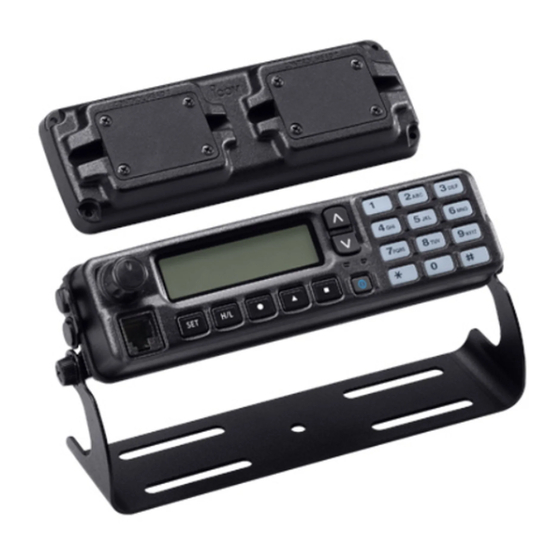
- Page 1 INSTRUCTION MANUAL SEPARATION KIT RMK-4...
-
Page 2: Explicit Definitions
CONTROL HEAD are attached. Icom, Icom Inc. and the Icom logo are registered trademarks of Icom Incor- However, if these items are dropped, dust-protection and splash... -
Page 3: Accessories
Function name KEY-STICKER Then, protect the attached stickers from coming off with the stickers RMK-4 (Main unit attachment) • Used for labelling supplied key cap, as shown below. the programmable function keys. See at right for details. -
Page 4: Table Of Contents
ACCESSORIES ..............ii TABLE OF CONTENTS ............iii 1 CONNECTION .............1–5 ■ Removing the transceiver’s main unit attachment ..1 ■ Connecting CONTROL HEAD and RMK-4 ....2 ■ Attaching the RMK-4 ............4 ■ Mounting ..............5 2 REMOTE BOX SET MODE .........6–8 ■... -
Page 5: Connection
Then unscrew the circuit board screw, and disconnect the separation cable, if it is connected. Front Front plate Remove the circuit board screw. Separation cable Main unit attachment IMPORTANT: Set the top, chassis and front screws aside as they are needed for the RMK-4 installation. -
Page 6: Connecting Control Head And Rmk-4
RMK-4 connections. Rear plate INFORMATION: CONTROL HEAD connected to the Separation Reinstall the circuit board [CONTROL HEAD 1] of the RMK-4, is recognized as the screw removed in step q cable main CONTROL HEAD. as shown at left to con- nect the cable terminal. - Page 7 Connect the opposite side of the separation cable that is the RMK-4. connected to CONTROL HEAD to the RMK-4. After the cable is connected, reinstall the front plate and the 4 screws. • The cable can be inserted into either the left or right grooves as needed.
-
Page 8: Attaching The Rmk-4
4 front screws that were removed from the main unit in step r in p. 1. (w) • Ensure the flat cable and the RMK-4 are connected/attached correctly, and not upside down. w Replace the screw that was removed from the main unit in step e in p. -
Page 9: Mounting
CONNECTION ■ Mounting D Overhead mounting 2 types of mounting styles are available— one is on-board mounting, and the other one is overhead mounting. Mount the controller securely with the 4 supplied screws to a solid surface which can support more than 2 kg (4.40 lb). D On-board mounting (Overhead mounting) Mount the controller securely with the 4 supplied screws to a... -
Page 10: Remote Box Set Mode
REMOTE BOX SET MODE The REMOTE BOX SET MODE is accessed at power ON ■ Set mode items and allows you to set seldom-changed settings. You can “customize” CONTROL HEADs for dual-head operation to The following functions (other than “RX Speaker Tune”) can suit your preferences and operating style. - Page 11 REMOTE BOX SET MODE D Panel Lock function D Hanger function Set the Panel Lock function to ON or OFF. (default: ON) Set the Hanger function to ON or OFF. (default: ON) The Panel Lock function locks all keys and the dial other than The microphone “on-hook”...
- Page 12 REMOTE BOX SET MODE D RX Speaker Tuning function D Intercom function Set the RX Speaker Tuning function to ON or OFF for CON- Set the Intercom function to ON or OFF. (default: ON) TROL HEAD 1 (main). (default: OFF) The Intercom function allows CONTROL HEAD operators to This function allows the operator of CONTROL HEAD 1 to communicate each other via their microphones.
-
Page 13: Dual-Head Operation
DUAL-HEAD OPERATION ■ Intercom function q Push [P3 (INTERCOM)] to enter the intercom mode. [P3] is used for the Intercom function ON/OFF switch when • The other CONTROL HEAD is also set to the Intercom mode the Intercom function is set to ON in the REMOTE BOX SET automatically even if this function is set to OFF. -
Page 14: Tx Af Monitoring Function
RMK-4. EXTERNAL SPEAKER The optional SP-22 is required. • The RMK-4 is not designed for the single-head operation. EXTERNAL SPEAKER For single-head operation, use the original attachment and NOTE: When one CONTROL HEAD operator is communi- cable combination— no RMK-4 is necessary. -
Page 15: Options
OPTIONS • OPC-607/OPC-608/OPC-609/OPC-726 SEPARATION CABLES Used for CONTROL HEAD and the RMK-4 connection. OPC-607 : 3 m; 9.84 ft OPC-608 : 8 m; 26.3 ft OPC-609 : 1.9 m; 6.3 ft OPC-726 : 5 m; 16.4 ft • HM-152/HM-152T/HM-148G/HM-148T HAND MICROPHONES... - Page 16 A-6757H-1US-q Printed in Japan 1-1-32 Kamiminami, Hirano-ku, Osaka 547-0003, Japan © 2009 Icom Inc.
Need help?
Do you have a question about the RMK-4 and is the answer not in the manual?
Questions and answers