DIGITIZE System 3505 Installation & Operation Manual
Hide thumbs
Also See for System 3505:
- Installation and operation manual (29 pages) ,
- Operation manual (12 pages) ,
- Manual (32 pages)
Table of Contents
Advertisement
Quick Links
Advertisement
Table of Contents

Related Manuals for DIGITIZE System 3505


Summary of Contents for DIGITIZE System 3505
- Page 1 System 3505 Installation & Operation Manual Digitize, Inc. 158 Edison Road Lake Hopatcong, NJ 07849 Tel: (973)663-1011 Fax: (973)663-4333 Part Number: 700248-0002 E-Mail: info@digitize-inc.com Revision: C Website : http://www.digitize-inc.com Issue Date: 02/16...
- Page 2 TRADEMARKS DIGITIZE (stylized) is a registered trademark of Digitize, Inc. First ... When Seconds Count. ISOdressable CGRMS Q-MUX All of the above are trademarks of Digitize, Inc. Any logos or product names mentioned in this document may be trademarks and are used for identification purposes...
- Page 3 The information contained herein is the property of DIGITIZE, INC. and may not be copied, disclosed or reproduced, in whole or in part, without the prior written approval of DIGITIZE, INC. Any unauthorized disclosure to, or use of the enclosed information by, unauthorized third persons shall void any and all representations, warranties and obligations on the part of DIGITIZE, INC.
- Page 4 FCC NOTICE In compliance with Paragraph 15.105 of the FCC Rules and Regulations, the following notice is provided. NOTE: This equipment has been tested and found to comply with the limits for a Class A digital device, pursuant to Part 15 of the FCC Rules. These limits are designed to provide reasonable protection against harmful interference when the equipment is operated in a commercial environment.
-
Page 5: Table Of Contents
TABLE OF CONTENTS GENERAL INFORMATION .................. 1-1 LISTING AND APPROVAL INFORMATION ..........1-1 ANSI/UL 864 STANDARD & SYSTEM SETTINGS........1-1 SYSTEM DESCRIPTION ................1-2 SYSTEM 3505 ....................1-2 ALARM TYPES ....................1-3 DISPLAY ......................1-3 MEMORY ......................1-4 1.7.1 MEM-600 Memory Chip ................. 1-4 SPECIFICATIONS .................. - Page 6 4.1.1 General ..................... 4-1 4.1.2 Control & Function Keys ................. 4-2 4.1.3 Access....................... 4-2 EXTERNAL KEYBOARD MENU SELECTIONS ........4-2 4.2.1 ZONE/MUX Menu .................. 4-3 USER TEXT TYPES ..................4-5 4.3.1 Generic ..................... 4-8 4.3.2 Control Panel Text ................... 4-8 4.3.3 Account Specific ..................
- Page 7 6.1.2 PRINT Button ..................6-1 6.1.3 KEY SELECT Button ................6-1 6.1.4 BOX LOOK UP Button ................6-1 6.1.5 DIALER LOOK UP Button ..............6-1 6.1.6 ZONE LOOK UP Button ................. 6-2 6.1.7 Numeric Keys ................... 6-2 6.1.8 CLEAR Button ..................6-2 6.1.9 Hyphen (-) Button ..................
- Page 8 6.4.10 Changing the Paper Tape ............... 6-11 6.4.11 Serial Output from the System 3505 ............6-11 DDI-9E & DDI-10E COMMUNICATOR RECEIVER CARDs ......7-1 OVERVIEW..................... 7-1 7.1.1 DDI-10E Setup ..................7-2 DDI-9E OPTION SETUP ................7-3 7.2.1 Caller ID ....................7-3 7.2.2...
- Page 9 DIGITIZE COMPUTER INTERFACE OPTIONS ..........9-1 OVERVIEW..................... 9-1 CAPS II: SYSTEM 3505 AUTOMATION INTERFACE ......9-1 9.2.1 General Information ................. 9-1 CAPS-II OUTPUT SETUP ................9-1 9.3.1 CAPS II OUTPUT SETTINGS..............9-2 9.3.2 Priority Level.................... 9-3 9.3.3 Handshake ....................9-3 9.3.4...
- Page 10 14.8 UPDATING THE MAIN PROGRAM OF THE SYSTEM 3505....14-6 14.9 INITIAL SET UP ................... 14-6 14.10 TEST PROCEDURES ................14-6 DIRECT WIRE INPUTS ................... 15-1 15.1 512 ZONE CONTROLLER ................15-1 15.2 REVERSIBLE POLARITY INPUT BOARD ..........15-1 15.3 END OF LINE (EOL) INPUT CARD ............
- Page 11 21.2 INSTALLING FROM CD ................21-1 21.3 INK COMMAND ..................21-4 21.4 SAVE ......................21-5 21.5 UPLOAD SYSTEM 3505 UPDATES VIA WIN 3505 ......... 21-6 21.6 RUN COMMAND ..................21-6 @ COMMANDS ....................22-1 22.1 OVERVIEW....................22-1 22.2 SST TELEGRAPH BOX TRANSMIT COMMAND (@B) ......22-1 22.3...
-
Page 13: General Information
1. The SYSTEM 3505 is shipped with O/S capability limited at a slave unit to only impact the Slave System 3505. The user can elect to activate a capability to allow a Slave System 3505 to take an account O/S at the master as well as at all the Slave units in a Networked System. -
Page 14: System Description
1.4 SYSTEM 3505 The overall unit is known as the SYSTEM 3505. The SYSTEM 3505 is a totally solid state System that uses state of the art devices and circuitry to continuously monitor and display the status of all System connected alarms. -
Page 15: Alarm Types
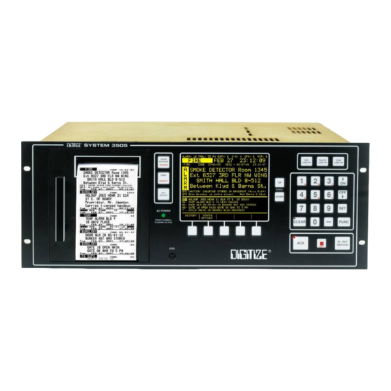
1.6 DISPLAY The SYSTEM 3505 front panel display (Figure 5-1 Front Panal Keyboard) provides detailed information to the operator. The first line indicates the current number of Alarms, Troubles, FA SUPV, Out of Service, DAY and Restorals. -
Page 16: Memory
System. Their availability is determined by the options installed in each unit. 1.7 MEMORY Each SYSTEM 3505 is supplied with 150 screens of nonvolatile, nonmagnetic, field programmable memory for storage of user text information. This memory is located in the “System”... - Page 17 4800 screens. The MBD-4800 contains all 4800 screens, and is installed in any of the card slots of the SYSTEM 3505. Each MBD-4800 has a DIP switch to use to set the address of the board. A total of eight motherboards may be installed in one System.
-
Page 18: Specifications
CAUTION: NEVER USE THESE CONNECTIONS TO POWER ANY OTHER DEVICES. Construction 1.8.4 The enclosure and cover of the SYSTEM 3505 is made of 0.062" aluminum. A membrane keypad is mounted on a 0.093" aluminum front panel. Dimensions 1.8.5 Height ............ 6.97" (17.7 cm) Width ............ -
Page 19: Temperature And Humidity
1.9 FCC REQUIREMENTS The SYSTEM 3505 complies with the limits set for a Class A computing device as specified in Subpart J of Part 15 of the Federal Communications Commission “Rules and Regulations”. -
Page 20: Trouble Reminder
1.10 TROUBLE REMINDER Per NFPA guidelines, the SYSTEM 3505 must alert the operator any time that a Trouble condition remains continuously active for longer then 24 hours. Each time a Trouble condition remains active for longer then 24 hours, the SYSTEM 3505 will print to the logging printer the current date and time along with the words "TROUBLE REMINDER"... -
Page 21: Installation
Font Selections 2.2.2 Through the 4 Set Menu on the System 3505, the user can select the print font and print quantity for each Alarm priority level, Trouble & Restore. The user can also select what to print for look up as well as FUNC 07. The two sample thermal printouts illustrate how the style can be modified for an Alarm, for example, and then the font for Trouble and Restore changed on the printout. -
Page 22: Edit Mode Selection
The print font changes are accomplished via the 4 SET MENU selections. To access these menus, enter 4 on the SYSTEM 3505 keypad, followed by pressing the SET key. Continue by pressing the FUNC key to enter the 4 SET menu. The prompt request the entry of the password, followed by pressing the SET key again. -
Page 23: Set Display Order
Set Display Order 2.2.4 The SYSTEM 3505 allows the selection of the order in which Alarms are displayed. The 39 SET menu is used to make these selections. Use the CHANGE UP or DOWN key to select between 1 & 6. Each selection changes the display order when an alarm is processed. -
Page 24: Changing The Thermal Paper
Check Blue lever on side of printer. 3. HEAD TEMPERATURE ERROR(Above 80c or less than –10c) Check environment unit is located in. Call DIGITIZE for tech support. 4. VP VOLTAGE ERROR(Below 10 or above 27 volts) Call DIGITIZE for tech support. - Page 25 System 3505 Installation & Operation Manual REORDER PAPER P/N: 900134-0005 Printer lever Place paper over guide pin. PLASTIC SPOOL 1. RAISE & LOWER PRINTER LEVER TO REMOVE REMAINING PAPER FROM THE PRINTER & ACTIVATE AUTO-FEED. 2. REPLACE EMPTY SPOOL WITH NEW PAPER ROLL.
-
Page 27: System Initialization
DC source, (i.e., batteries and charger), such as the DIGITIZ SEBB-6/24 (P/N 425403-0001). This is to be connected after the unit is operating on the AC source. 3.4 POWER-UP To power up a SYSTEM 3505, primary AC can be applied first, then the standby DC power may be applied. AC Power 3.4.1... -
Page 28: Program Initialization
System 3505 Installation & Operation Manual PROGRAM INITIALIZATION Upon power-up, the SYSTEM 3505 will momentarily display the following screens, in sequence, while performing internal diagnostic tests: COPYRIGHT© 2001 DIGITIZE SYSTEM 3505 Initializing Test CPU7 FLASH Checksum Checking CPU-VII Checking Lower RAM PASSED... -
Page 29: Connections And Settings
System. Install the various options that were ordered, and then reconnect the power. The connections for the options will be shown in the various sections of this manual. • The SYSTEM 3505 will print "Option Disabled" for any installed option that has been "turned off."... -
Page 31: User Text
Insert the plug of the DIGITIZE external keyboard into the keyboard jack on the front panel of the SYSTEM 3505. The SYSTEM 3505 will automatically go to the 2 SET mode if there are no active conditions to acknowledge Press the F1 key on the external keyboard to gain access to the password menu. -
Page 32: Control & Function Keys
System 3505 Installation & Operation Manual entered. If an incorrect password is entered, the System will sound the “Entry Error” tone momentarily and the display will prompt for re-entry of password. Control & Function Keys 4.1.2 KEY (S) FUNCTION Press F1 to activate the Field Programmable mode. This is the first sequence which should be entered after plugging in the External Keyboard. -
Page 33: Zone/Mux Menu
LEVEL 7 ALM LV7 LEVEL 8 ALM LV8 (reserved for SYSTEM 3505 use) Priority Level 8 is reserved for the SYSTEM 3505 to automatically assign to any alarm that has no message programmed for it. Priority Level 8 also has significance should the System be expanded into a network configuration. - Page 34 Reverse Polarity type interface cards will match the zone number for which text is entered with the point input number. These numbers range from 1 through 2048. When entering numbers for the Digitize Mux System, enter the Muxpad panel number followed by the zone number.
-
Page 35: User Text Types
24 x 2 character lines, in which case the spacing created by the user will be honored. The message can also be displayed as one long line, in which case the SYSTEM 3505 will remove multiple blanks by left justifying the text. -
Page 36: Generic
When DGM 23-05 is received as an alarm, he display will bring up page 1 of the account specific message in large type. The SYSTEM 3505 will present the remainder of the text message in small type just below the account specific message. - Page 37 !!FIRE 555-1234 FUTOFF VALVE CORNER ELM AND BROAD ST The user may also press the ZONE LOOK UP key on the SYSTEM 3505 to view the other pages of text messages. After pressing ZONE LOOK UP, the SYSTEM 3505 will present the text screens in this order: page 1 of the account specific, page 1 of the generic (if any), page 2 of the generic (if any), page 3 of the generic (if any), etc.
-
Page 38: Control Panel Text
Control Panel Text 4.3.2 The user has no control over Control Panel text at the SYSTEM 3505. This CP text originates at the building being monitored by the control panel, such as an FACP. Any Changes to the account text message at the building will display and print at the SYSTEM 3505 the next time that account is activated. -
Page 39: Deleting Zone Text
ADD, CHANGE, or DELETE is 7, then enter 345-07 when the display asks for DIALER number to be ADDED. NOTE: The SYSTEM 3505 will always process a 3-1 and 4-1 dialer will always display a two digit zone. Thus, account 123-1 will be processed as 123-01. -
Page 40: Radio Telegraph Menu
For example, a radio box and a telegraph box cannot each have the number 345. IMPORTANT! Do not enter leading zeros to any number. The SYSTEM 3505 will always process a 3-1 and 4-1 dialer will always display a two digit zone. -
Page 41: Password Menu
System 3505 Installation & Operation Manual To change settings, make a numeric selection to advance to the appropriate screen. Use selection 1 to set the transmission speed to a fast setting. 1=FST 2=SL 3=DGM 4=INDEX/RATIO Password Menu 4.3.10 To change the current password, ender the “C” then press the RETURN (or ENTER) key. -
Page 42: Exit Data Entry Mode
Total Pages Installed, Used, and Deleted 4.3.12 Each time the SYSTEM 3505 is powered up or the RESTART button is pressed, the printer will print out the total number of pages installed, used, and deleted in the Field Programmable mode. The total number of pages installed will also be printed out whenever CTRL, P is entered when using the Field Programmable mode. -
Page 43: Front Panel Access
System 3505 Installation & Operation Manual FRONT PANEL ACCESS OVERVIEW Many functions for System operation can be accessed through the front panel keyboard. By pressing the SET button, the operator may step through all available menus. If pressed for over one second, the SET button will auto-repeat. - Page 44 As described in the message above, pressing the FUNC button will select the MENU shown and move the cursor to the first selection of that Menu. Refer to Appendix B, System 3505 Step-by- Step Procedures for detailed direction for each menu.
-
Page 45: Setting Time & Date
System 3505 Installation & Operation Manual those Systems with the OPTIONS installed. Please look for the word OPTION in the relevant section headings to differentiate between standard and optional features and their relevance to the user. 5.2 SETTING TIME & DATE Press 1, then the Set button. -
Page 46: Thermal Printer Intensity Printing Modes
System 3505 Installation & Operation Manual Press FUNC to edit this menu. The display will read: The next display will read: The programmable keys located below the display screen should be flashing, with options. The tones for each priority level can be modified for preference of sound. -
Page 47: Serial Port Communications
System 3505 Installation & Operation Manual • 1=EDIT MODE SELECTION. Use the numeric keypad to enter 1 to select the Edit Mode option. • 2=ASSIGN MODE TO COND. Use the numeric keypad to enter 2 to select the Assign Mode to Cond. -
Page 48: In/Out Service, Password, Priority Level
Slave System 3505. The user can elect to activate a capability to allow a Slave System 3505 to take an account O/S at the master as well as at all the Slave units in a Networked System;... -
Page 49: In/Out Service Password
To change a password requirement to YES or NO, select the desired level screen, and press FUNC twice. The underline should now be at the first character of YES or NO. Use the ↑↓ keys on the System 3505 keypad to toggle the word from YES to NO or NO to YES. -
Page 50: Radio Box Option Setup
System 3505 Installation & Operation Manual Press the FUNC button to edit this menu. Enter password, if prompted. The display will read: Use this menu to configure the optional Telegraph Transmitter. Use the numeric keypad to make selections. Press 1 to set up the SST FAST speed requirements. - Page 51 System 3505 Installation & Operation Manual 1= OVERRIDE BOX DECODE FORMAT Enter “1”; a new sub menu will appear. The display will now read: If the NO setting is left in place, no changes will be made to Radio box format. When “Set to Yes”...
- Page 52 (i.e., 5-1, 5-2, or 4-2 and 4-1). By using the ‘-A” seletionc, the System 3505 will check each box number decoded to see if a single or dual funciton tone setting was enetered for the daily test. It will use this information to determin if the box should be decoded as a single or dual toane box.
- Page 53 1 is in use. The greater the number of digits, such as 4-2 or 5-2, the less prone the system will be to false box decoding. The System 3505 also implements a process where each tone length is checked to insure that it meets a minimum an dmaximum time requirement as part of its false box display detection, in addtion to the “Yes/No”...
-
Page 55: 1221 Rad Test Box Option
Set to YES (via CHANGE UP/CHANGE DOWN programmable keys or the ↑↓ keys), requires the System 3505 to process the detection of a low battery condition at the radio box as a Trouble. If set to NO, no Trouble state will be displayed, however the battery fault will be presented when the negative box report is printed. - Page 56 Enter “12”, and then press the SET button and the display will read: Press FUNC to edit this MENU. Enter password, if prompted. The display will now read: • Press “1” to set up the time when the SYSTEM 3505 will report ‘no box received’. The display will now read:...
-
Page 57: Status Printout Setup Mode
SETUP Press the FUNC key to move between the hour setting and the minute setting. Use the ARROW keys on the SYSTEM 3505 front panel to change the settings. Press the CLEAR key to return to the main set menu. -
Page 58: Day/Night Option Set Up Mode
FUNC button to move the cursor to the various user changeable fields. Use the - keys or the numeric keypad on the System 3505 to make changes. All changes are made as they are entered and will be in effect if the DAY mode is currently active. Press the CLEAR button to EXIT the menu. -
Page 59: Addressable Line Printer Option Set Up Mode
Each line printed on a printer represents the complete display of each screen (page) entered in the setup for a specific zone. The System 3505 Addressable Line Printer option normally supports up to eight addressable line printers. -
Page 60: Sleep/Awake Select Option
System 3505 to wake up. NOTE: After configuring the System 3505 for Sleep Mode, the user must return to 18 SET and press the CHANGE TO FCTRY DFLT soft key to update all the conditions. Additionally, each time new options are added to the System 3505, or a configuration changes, the user must press the soft key indicated by “Change TO FCTRY DFLT”... -
Page 61: Telegraph/Digital Dialer Auto Clear Setup
System 3505 Installation & Operation Manual Enter “18”, press the SET button and the display will read: Enter password if prompted. Press the FUNC button to select this screen. The next screen will read: Users may want to press “PRINT SET INFO” before making changes to accounts; the record can be useful when correcting any data entry errors. -
Page 62: Batt Supervision
System 3505 Installation & Operation Manual Press the FUNC button to select this screen. Enter password, if prompted. The next screen will read: Use the FUNC button to move between fields; use ↑↓ keys to change values. By defining these settings the user is permitted to have Box and Digital Dialer messages cleared automatically after the desired interval. -
Page 63: Direct Wire Delay Setup
System 3505 Installation & Operation Manual • Press (or CHANGE UP/CHANGE DOWN) to set selections to Y (yes) or N (no) as ↑ ↓ needed. • Press ADVANCE TO NEXT FIELD or FUNC button to move between fields. . • Press CLEAR to ABORT or EXIT SETUP 5.18... -
Page 64: Alarm/Trouble Relay Setup
System 3505 Installation & Operation Manual Press the FUNC button to select this screen, and enter password if prompted. The next screen will read: • Press SET, ↑ or ↓ to select next MENU. Press CLEAR to ABORT or EXIT SETUP -or- •... -
Page 65: How To Process Teleg Option Setup
System 3505 Installation & Operation Manual Press the FUNC key to move between fields. Use ↑ or ↓ to change values. Press the CLEAR key to save changes and return to main set menu. 5.21 HOW TO PROCESS TELEG OPTION SETUP Enter “25”, and then press the set button. -
Page 66: 1221 Rad @X Option Setup
System 3505 Installation & Operation Manual 5.22 1221 RAD @X OPTION SETUP Enter “26”, and then press the SET button. The display will read: Press the FUNC button to select this screen. Enter password, if prompted. The next screen will read: Press the FUNC key to move between fields. -
Page 67: Operation
System 3505 Installation & Operation Manual OPERATION 6.1 CONTROLS PAPER ADVANCE Button 6.1.1 This button will rapidly advance the paper tape of the thermal printer. The paper will continue to advance as long as this button is held. PRINT Button 6.1.2... -
Page 68: Zone Look Up Button
When there is nothing to clear and the clear button is pushed, the system will momentarily display the day of the week on the lower line of the display. This also causes the SYSTEM 3505 to advance to the next display if more than one item is rotating. -
Page 69: Set Button
Slave System 3505/. The user can elect to activate a capability to allow a Slave System 3505 to take an account O/S at the Master as well as at all slave units in a Networked System. -
Page 70: Shift Key ( )
• If the SYSTEM 3505 is supplied with only zones, then simply enter the zone number and press the IN/OUT SERVICE button. -
Page 71: Status
6.1.18 The REPORT key is used to print the NEGATIVE DIALER as well as the missed radio box report. If the SYSTEM 3505 has the NEGATIVE DIALER report or MUNICIPAL type RADIO boxes, then press REPORT to indicate what DIALERS and or BOXES have failed to report in within the last 24 hours. The REPORT button is the second function of the PRINT key. -
Page 72: Transmit Sst Fast
System 3505 Installation & Operation Manual Transmit SST Fast 6.2.5 Once satisfied the box number and the number of rounds have been loaded correctly, press the TRANSMIT SST FAST button to start box transmission via the SST fast relay. 6.2.6 Transmit SST Slow... -
Page 73: Indicators
The scrolling message will advise what steps to take next. 6.3 INDICATORS AC Power 6.3.1 When external 24VDC power is connected to the SYSTEM 3505 the indicator will flash during a loss of AC power. It remains at steady illumination during normal operation. Digitize, Inc. 700248-0002 Rev. C 02/16... -
Page 74: Condition Indicator
When an alarm is actuated, the user programmed priority level will determine the response of the SYSTEM 3505. Of course if only one alarm is active, it will be displayed and processed regardless of the priority level. If this alarm is not Digitize, Inc. -
Page 75: Normal Quiescent Operation
ACKnowledged. The SYSTEM 3505 will process one alarm at a time. If a second lower or equal priority alarm is received, prior to acknowledging the current alarm, the fourth line of the display will flash “NEW ALRM WAITING”. -
Page 76: Taking A Zone Temporarily Out Of Service
System 3505 Installation & Operation Manual Taking a Zone Temporarily Out of Service 6.4.5 If a particular zone is known to have problems, and continues to come in as TROUBLE or ALARM, it can be taken out of service until the problem is corrected. -
Page 77: Message Display For A Telegraph Or Dialer
Serial Output from the System 3505 6.4.11 Data on the alarms into the SYSTEM 3505 SYSTEM can be sent out over a two- wire serial data link. One such use is a Computer Aided Dispatch. The output is based on standard data output format with a selection of preset BAUD rates from 150 to 9600. -
Page 79: Ddi-9E & Ddi-10E Communicator Receiver Cards
The dialer option software provides conversion of coded information from the receiver into the proper format for processing by the SYSTEM 3505. In the case of a redundant SYSTEM 3505 configuration, each SYSTEM 3505 requires a Digital Dialer interface option. -
Page 80: Ddi-10E Setup
Restoral = Y and the dialer would send a restoral automatically, thus restoring the account on the SYSTEM 3505. All active accounts are maintained on the SYSTEM 3505 until restored. If an abnormal condition occurs (i.e. the dialer is reset and no restoral will be received) the operator may also clear the condition as follows: when the dialer message is on the display, press DIALER LOOK UP;... -
Page 81: Ddi-9E Option Setup
Enter “16”, press the SET button and the display will read: Press the FUNC button to select this menu. Enter password, if prompted. Refer to Appendix B, System 3505 Step-by-Step Setup Procedures for set up details. (The DDI-9/10E are not an ETL Listed Component.) Caller ID 7.2.1... -
Page 82: Contact Id
Leading zeros will be left blank. For example, on account 234 the Contact ID account number may be 23401008. Account number to the SYSTEM 3505, when added, can be assigned to any group (i.e. 1 –8). The group fields are not used when receiving a Contact ID account, however, the dialer must be assigned to one of the 8 groups in order for the Negative Dialer report to operate properly. -
Page 83: Parallel Printer
Digital Dialers operate. Each individual Digital Dialer subscriber must be added to the SYSTEM 3505 (via the 16 SET menu). After installation of the DDI- 9/10E, the user will access the Set Up Mode through the front panel keypad. By pressing the SET button, the user may step through all available menus. - Page 84 The copied file can then be edited and changes as needed to meet the desired altered configuration. 4 = Convert SIA designations to Contact ID text – The SYSTEM 3505 takes any incoming SIA accounts and converts them to CID format. This selection allows set up of the needed conversion.
-
Page 85: Pulse Dialer Format Primer
CID/SIA accounts. The only purpose to adding a CID/SIA account is to log in that account, so the SYSTEM 3505 does not complain of about receiving an unknown account and to provide a negative report that the dialer failed to report in. - Page 86 The SYSTEM 3505 will check on all eight config tables for any that contain duplicate zone codes upon exit of the 16 ET menu or upon power-up of the SYSTEM 3505 uit. Do not enter the same subscriber account regardless of the config table used. The SYSTEM 3505 will not accept duplicate subscribers.
-
Page 87: Configuration Tables
7.4 Configuration Tables The SYSTEM 3505 is shipped with Configurations 1 and 2 set as the factory default settings. To change any default settings and/or to set up other Configuration tables, follow the instructions outlined in this section. Figure... - Page 88 System 3505 Installation & Operation Manual Selection #2 will display: Configuring the English part of the Conversion Tables 7-10 Digitize, Inc. 700248-0002 Rev. C 02/16 Specification Subject to Change Without Notice...
- Page 89 The cursor is on the first field (CONFIG #) After entering the desired CONFIG table number, press PRINT SET INFO to obtain a copy of the existing settings. Use the FUNC button to move to the next field (ZONE). The SYSTEM 3505 is shipped with Config table #1 & #2 preloaded.
-
Page 90: Set English Equivalents
The SYSTEM 3505 can be set up to allow a single opening or closing code, or an expanded format to allow up to 16 opening and closing codes. When entering a unique zone number next to the English descriptor “OPENING”, the system will... -
Page 91: No Cust
E2 was used as a data loss signal, however, the system may use other codes to represent the Data loss signal. Not that the English zones always append the actual zone that came in as part of the SYSTEM 3505 account number. No Cust # 7.4.5... - Page 92 “Y” for this timer to apply to this account. • 24Hr/XX.X = Y or N – Set to “Y” the SYSTEM 3505 will use this time interval to check that the dialer reported in within this time frame. The SYSTEM 3505 will report a subscriber failure should 15 minutes laps after the scheduled time frame.
-
Page 93: Copy Configurations
When using a dialer that reports via the SIA protocol, check the CID/SIA tables installed in the SYSTEM 3505 and verify that all of the desired SIA codes are included. If not, add the desired SIA codes. Please note: it easier to copy System 7-15 Digitize, Inc. -
Page 94: Various Setup Selections
System 3505 Installation & Operation Manual messages for the SYSTEM 3505 using the WIN3505 program, and to then use the WIN3505 utility to make the desired changes. Upload the user text, but simply select upload CID/SIA info only. This will update the system as well. -
Page 95: Force A Daily Test For Various Codes
Various dialers use various event type codes. If Y is selected for any or all three of these CID codes, then when the SYSTEM 3505 processes these ID codes, it will check its entire Alarm queue and restore all event type belonging to the same subscriber. -
Page 96: On The Fly Zone Conversion
Sort Customer in Order and Exit 7.4.13 When selected, the SYSTEM 3505 will sort all of the present dialer accounts into numerical order and then exit the 16 SET menu. The purpose of sorting the dialer accounts is so that any missed dialer reports print out in numerical order. -
Page 97: Ddi-9E Led Indicators
Simply route the RS-232 signals via the T-Bar so that the online unit has access to the DDI-9/10E. Fire code requires two phone lines to the monitoring equipment. On SYSTEM 3505 units with DDI-9/10E, if the first phone line is unable to make a connection, the phone automatically hunts to the second phone line. -
Page 98: Fcc Information
On installations with two SYSTEM 3505 units, automatic transfer, and a DDI-9/10E module for each unit, the backup SYSTEM 3505 provides a second system of coverage. In this case redundant operation would require at least two SYSTEM 3505 units and two DDI-9/10E modules. -
Page 99: English Equivalent Worksheet
System 3505 Installation & Operation Manual Zones Settings Worksheet: Configuration #1 ZONE ZONE ZONE English Equivalent Worksheet Configuration #____________ PROCESS DAILY TEST SECURE ALL OPENING CLOSING AC FAILURE AC NOW OK LINE 1 FAULT LINE 1 OK GROUND FAULT GND NOW OK... - Page 100 System 3505 Installation & Operation Manual LINE 2 OK DATA LOSS PNL TBL 24 HR FIRE DRILL DRILL RSTR NO BATTERY BAT PRESENT NAC #1 FAULT NAC #1 RSTR NAC #2 FAULT NAC #2 RSTR COMM TBL PRT COMM PR1 OK...
- Page 101 Upon notification, operators will be given the opportunity to correct the problem and informed of the right to file a complaint with the FCC. CAUTION! Changes or modifications not expressly approved by Digitize, Inc. could void the user's authority to operate the equipment.
-
Page 102: Dialer Look-Up
System 3505 Installation & Operation Manual English Equivalent Worksheet Configuration #____________ PROCESS FOR DAILY TEST SECURE ALL OPENING CLOSING AC FAILURE AC NOW OK LINE 1 FAULT LINE 1 OK GROUND FAULT GND NOW OK BATTERY FAIL BATTERY OK LINE 2 FAULT... - Page 103 System 3505 Installation & Operation Manual 1. Press the DIALER LOOK UP key on the front of the SYSTEM 3505, without entering any text. The display will look as follows: Note that the display is prompting for a 12 digit entry, which is the actual minimal length of a CID/SIA account.
- Page 104 System 3505 Installation & Operation Manual After entering the 401-01, as used in the example, now press the DIALER LOOK UP button and the display will “LOOK UP” the text associated with the account entered. End of Chapter 7-26 Digitize, Inc. 700248-0002 Rev. C 02/16...
-
Page 105: Mux Multiplex System
Each Q-node can control up to 63 mix/matched ID modules. Up to 32 Q-Nodes may be used in one system. Total range of the Q-Mux system is 5,000 feet from the System 3505 to the last Q-Node and 5,000 feet from the Q-Node to the last ID module. ID modules may be set to any address from 1 to 63. - Page 106 After Q-MUX has been installed, the operator will access the Set Up Mode through the SYSTEM 3505 front panel keypad. By pressing the SET button, the operator may step through all available menus. If pressed for over one second, the SET button will auto repeat.
-
Page 107: 1=Add/Chg/Del Id
System 3505 Installation & Operation Manual Press the FUNC button to edit this menu. Enter password if prompted (factory default is 2222; Password can be changed via the keyboard. If the password for this level has already been changed, enter the new password). The next display, Q-Mux Setup, will appear: The operator must enter ‘1’... -
Page 108: Installation
The command must have the dashes as shown or it will not operate. If a short is placed on INPUT 1 on the rear of the SYSTEM 3505, it will skip the box transmission while the input is shorted. -
Page 109: Relay Control
System 3505 Installation & Operation Manual The SST SLOW relay will code out the same box number as the Q-IR or Q-I/O device. Pressing the STOP key will abort both the SST SLOW and the SST to the Q-Mux device. To transmit only via the SST SLOW (or FAST), use the @B command in place of the @Q command. -
Page 111: Digitize Computer Interface Options
DIGITIZE offers several Automation interface options for the SYSTEM 3505. These options include CAPS, CAPS II, D-LAN and custom interfaces. The computer interface options allow the SYSTEM 3505 to send ALARM, TROUBLE & SECURE Conditions via a serial port to Automation systems. Digitize offers its own automation systems called CGRMS, which provides the user with an interactive interface between the SYSTEM 3505 and CGRMS. -
Page 112: Caps Ii Output Settings
CAPS II OUTPUT SETTINGS 9.3.1 The Set 29 menu defines the parameters under which data is sent by the System 3505 to the Automation system (PC). In the following illustration, please note the optional settings available. -
Page 113: Priority Level
System 3505 Installation & Operation Manual 2) Forward Daily tests. Set to yes, the System 3505 will forward daily tests, as the report into the SYSTM 3505, to the Automation system; set to N (no), will stop the SYSTM 3505from forwarding the daily test to the Automation system. -
Page 114: Baud Rate
The CAPS protocol is the predecessor to CAPS II and is basically a one way communication between the SYSTEM 3505 and the automation system. While this interface is available to support legacy systems, it is not recommended for new applications as it lacks any supervision as a one way protocol. -
Page 115: Dlan Option
D-LAN SET UP (34 SET MENU) The 34 SET menu is used to set up the D-LAN option for the SYSTEM 3505. SET 34 menus 1, 2 & 3 allow the end user to set up how the D-LAN option should operate between the 3505,... - Page 116 TOGGLE Y/N– Changes the selection between Y and N on each key press. Changes are activated in the SYSTEM 3505 as they are entered. The TOGGLE Y/N key is also used to change the SEND MULTI PAGES and SEND SINGLE PAGE.
- Page 117 The factory default for this selection is N. Send DDI or RAD DAILY Test Signals- Set to Y, the SYSTEM 3505 is set to pass the daily tests that it receives from dialer or radio systems to the D-LAN. The automation system selected must have a process to keep track of these daily tests and report any missed dialers or radio boxes via the automation system.
- Page 118 1. SEND 3505 ACK to D-LAN option and SHOULD OPER ACK FROM D-LAN, ALSO ACK THIS 3505 UNIT option should not both be set to Y. If both are set to Y, the SYSTEM 3505 will only respond to SEND 3505 ACK to D-LAN.
-
Page 119: Integraton Of The D-Lan Option, Remote Annunciator & Smart-Ip Card
This card functions as a replacement for the Lantronics configurator card and plugs into port 16 on the System 3505. It is superior in that it can transmit 3505 DLAN output to as many as 10 remote devices (typically Remote Annunciators). It supervises the link with each device that is configured. -
Page 121: The Remote Annuciator
This also applies to software updates of the Remote Annunciator, and options upgrades for SMS and SST. The Smart IP Card equipped System 3505 will use wild card addresses (i.e., 0000) to address “I am talking to” functions, and does not need the FFFF. -
Page 123: Network
Slave System 3505. The user can elect to activate a capability to allow a Slave System 3505 to take an account O/S at the master as well as at all the Slave units in a Networked System;... -
Page 124: Network Option Setup
A variation of the second option using the 32-line driver rack is to set up to individual line driver cards to communicate with a single Slave SYSTEM 3505. The advantage here is that line drivers can be “mix and match” line, providing a true path redundancy. -
Page 125: 1= Should I Menu
3= Delete Slave unit(s) 12.2.3 This menu is used to delete a slave System 3505 unit or units from a Networked System. The address (1-99) of the slave unit is entered using the numeric keys. The soft key, “Activate Selection Now”, must be pressed to remove the 12-3 Digitize, Inc. -
Page 126: 4=Use O/S From Slave
3= Slave ID number Use this menu to set the Slave number for this System 3505. 4=Send O/S to Master When set to Y (yes), the slave will send a request to the Master System 3505 to take the account O/S. 12-4 Digitize, Inc. -
Page 127: Setting Network Address
Burglary Alarms. At Slave #2, the response would then be ‘No’ to the screen that asks ‘Should I RX Burglary’. The SYSTEM 3505 units can also be instructed to send or receive an ACK or CLR. Continue to scroll through the SET OPTIONS menus to program ACK or CLR conditions. Certain Slave units may be programmed to receive an alarm for the purpose of information only. -
Page 128: Redundant Operation
ACK the local System 3505 on good transfer of an account to the RA, or ACK the System 3505 if the operator ACKs the RA, or to send any of these ACK signals on the network to allow selection of processing the ACK at another System 3505. -
Page 129: Cross Ack, Clear & Cross Data
CLEAR and external keyboard entry mode. If an alarm is received on two or more SYSTEM 3505 units, the user has the ability to ACKnowledge all units by pressing the ACK button on one unit. NOTE: SYSTEM 3505 units must be installed within the same room in order to use the CROSS ACK option. Installation 13.1.1... -
Page 131: Telegraph Coded Interface
The Telegraph Coded Input, TCI, may be added with any other option into the SYSTEM 3505. The TCI allows the SYSTEM 3505 to receive an alarm via a coded telegraph alarm line. The TCI option allows for 20 circuits of telegraph code per alarm monitor card inside of the SYSTEM 3505. -
Page 132: Operation
3505 for processing. The code will be processed and printed out on a round-by-round basis. The screen on the SYSTEM 3505 will display the incoming circuit number, as well as show the box decoding. It will also display that the alarm is an incoming telegraphic alarm. The audible alert will be activated;... -
Page 133: Telegraph Check Option Setup
System 3505 Installation & Operation Manual NO Dry Relay Contacts NC Dry Contacts The unit will take care of “OPEN” or “CLOSED” index code wheels automatically. The different type of input PCB’s plug into the input panel assembly with the five gold pins to the left side (connector side view). -
Page 134: Selt Test Option Setup
System 3505 Installation & Operation Manual Selt Test Option Setup 14.4.1 Enter “28”, press the SET button and the display will read: Press the FUNC button to select this screen. If prompted, enter password. The following screen will read: Press the FUNC key to move between fields. Use ↑ or ↓ to change values. Press the CLEAR key to save changes and return to main set menu. -
Page 135: General Specifications: Tci Option Only
System 3505 Installation & Operation Manual Figure 14-1: Switch Pack Setting Alarm Monitor 20 14.7 GENERAL SPECIFICATIONS: TCI OPTION ONLY Input alarm signal (selectable by alarm interface board): Loop current 100 MA+50% Repeater bus 24+ VDC NO Dry relay contact NC Dry relay contact Open or closed index decoding with any of the above configurations. -
Page 136: Updating The Main Program Of The System 3505
1. Activate a telegraph box so that it sends an alarm to the SYSTEM 3505. 2. Monitor the SYSTEM 3505, being sure that it decodes the telegraphic box. As the box is coding in, the screen will display the following:... - Page 137 (where H= hours, M= minutes and S= seconds. The display will hold the message.) 7. To clear the alarm from the SYSTEM 3505, press the CLEAR button on the upper keypad while the CLEAR LED is blinking. When the alarm clears, the printer will display:...
-
Page 139: Direct Wire Inputs
The Direct Wire Input is composed of one or more 512 zone controllers, depending on the total number of input lines to be monitored. The SYSTEM 3505 is supplied with one (1) 512 zone controller. The different types of interfaces are: End-of-Line (EOL) resistor, supervised;... - Page 140 System 3505 Installation & Operation Manual NOTE: Under special order, EOL boards can be supplied to monitor non-standard or existing End-of-Line Resistor values. End of Chapter 15-2 Digitize, Inc. 700248-0002 Rev. C 02/16 Specification Subject to Change Without Notice...
-
Page 141: Multiplex
Digitize Multiplex option. The Multiplex option operates in conjunction with all other options available in the SYSTEM 3505. The SYSTEM 3505 can support 500 DGM panels with a maximum of 32,000 input zones and 32,500 output points. The SYSTEM 3505 can support 500 Muxpads with unlimited input zones via the FACP interface, as well as 500 output points. - Page 142 DGM panel, change the type of DGM number with the keys back to “NONE INSTL’D”. Some SYSTEM 3505 units require restart to activate new DGM/Muxpads added or removed. By pressing FUNC to place the cursor on line 3 of the display, information for the “User Text” area can be entered. With the cursor on line 3, insert the external keyboard into the KBD port on the front panel, and type the desired message.
-
Page 143: Line Type/Sel
System 3505 Installation & Operation Manual "DO NOT SELCT~" "FC-ID/A & X ~" "7200 3.X/4.X~" " AM1010 ~" " AM2020 ~" " SPECTRONIX ~" " DGM-ISO-8L ~" "FLX500 MXPD1~" "FCI-7100, E3~" "FLEX 630\650~" "SIMPLEX 4X20~" " FCI-7200 ~" "IRC-3, EST-2~"... -
Page 144: How Should I Respond
SETUP Two settings can be changed within this menu. Process OPERATOR Sig. can be set to either Y (yes) or N (no). The SYSTEM 3505 will process operator signals, or not, based upon this selection. VERIFCATION Signal can be set to TROUBLE or NOTHING. -
Page 145: Multiplex Single Line Out Option
FACP are sent to the SYSTEM 3505, but are routed to an FACP Fault log. Each time a FAULT is added to the log, the SYSTEM 3505 will make a short buzzing sound. The STATUS soft key will change to FACP FAULTS. -
Page 146: Dgm Types
DGMs are surface mounted units designed for the receiving and processing of point status changes, and the transmission of data to the SYSTEM 3505. Available DGMs are described below. Each DGM model can be ordered with the Polling Radio (RF) option. DGM 32/64 models can be purchased with 8, 16, 24, 32 or 64 installed zones as well as relays in strips of 8 up to 64 total relays. -
Page 147: Muxpad Ii
Muxpad is provided with a single FORM C relay contact that may be controlled by the SYSTEM 3505 with the addition of the relay control option. Each Muxpad II provides a serial interface to a selected FACP as well as eight EOL resistor zones. - Page 148 Low Temperature (Custom applications only) Style 6 Communications Error When a DGM fault is processed by the SYSTEM 3505, the fault account is a combination of the DGM number and the fault code. Thus DGM 123, with a battery fault condition would produce account 123-F2.
-
Page 149: Zone-Dialer-Box (Zbd) Option
17.1 OVERVIEW The ZBD option for the SYSTEM 3505 allows the unit to receive a telegraphic code from the Telegraph Coded Input (TCI) and then turn on one or more points on the 64 T output card. The individual outputs can be field programmed for which code turns on which output. For connections see #800321 installation drawing. -
Page 150: Function 46
To output this, press “4”, “5” and FUNC. Function 46 17.3.2 To have the SYSTEM 3505 print out the full point output as programmed press ‘‘4’’, “6” and FUNC. The unit will respond with the point number and the box code that will activate the point. -
Page 151: Test Mode
12000003. When testing accounts that are in a test mode, the SYSTEM 3505 will log any activity to the thermal printer. The information is also sent to all Network units, as well as the Automation Systems, via the D- LAN protocol. - Page 152 System 3505 Installation & Operation Manual Figure 18-2 VIEW TEST MASKS Figure 18-3 TEST MODE 4X2 Figure 18-4 TEST MODE CID DIALER 18-2 Digitize, Inc. 700248-0002 Rev. C 02/16 Specification Subject to Change Without Notice...
- Page 153 System 3505 Installation & Operation Manual Figure 18-5 TEST MODE PRINT REPORT End of Chapter 18-3 Digitize, Inc. 700248-0002 Rev. C 02/16 Specification Subject to Change Without Notice...
-
Page 155: Day Night Mode
ALARM. However, the open door is still an event internal to the SYSTEM 3505. In addition to the open door in the DAY mode, 499 more events can be processed. If the door were to close while still in the DAY mode, it would no longer be counted as an event. - Page 156 System 3505 Installation & Operation Manual If the system does not have the DAY/NIGHT option installed, the words (NEEDS OPTION) will be displayed. The display will read: This menu allows full control of the DAY/NIGHT features. Each time the FUNC button is pressed, the blinking cursor will advance to the next field.
-
Page 157: Activation Of Day Mode
SYSTEM 3505 internal stack. The SYSTEM 3505 will process up to 500 NON- SECURE items at any one time. At the end of the SYSTEM 3505 display rotation, a screen indicates that the user has reached the end and indicates how many items are active (displayed). -
Page 158: Day Mode Trouble Conditions
System 3505 Installation & Operation Manual 19.7 DAY MODE TROUBLE CONDITIONS Any ZONE, DIALER, or BOX, while in the DAY mode, will still process a TROUBLE condition as it would normally when not in the DAY mode. Day Mode Priority Level 1 19.7.1... -
Page 159: Sst-3505 Solid State Transmitter
System 3505 Installation & Operation Manual SST-3505 SOLID STATE TRANSMITTER 20.1 OVERVIEW The programs in this section require that the Solid State Transmitter (SST) option be ordered. Some require the addition of other options in order to operate. 20.1.1 SPEED TRANSLATOR OPTION FOR SST TRANSMITTER Enter “10”, press the SET button and the display will read:... -
Page 160: Manual Sst
20.2 TPO-2 AUTO TRANSMISSION This is a standard feature with the SST-3 in the SYSTEM 3505. It allows the last received alarm to be loaded directly into the transmitter. When the alarm has been received, push one of the Transmit keys. The received box number will be loaded into the transmitter. When the programmable key XMIT/STOP or XMIT SLOW is pressed the appropriate relay will code out the box number. -
Page 161: Solid State Zone Coder
SST-4 SOLID STATE ZONE CODER 20.2.3 The Solid State Zone Coder provides the SYSTEM 3505 with the ability to output a pulse coded telegraphic alarm upon receipt of a zone ALARM condition. The SST-4 is completely Field Programmable for 1 through 9 digits, as well as the number of rounds for each. -
Page 162: Non-Parity Program
System 3505 Installation & Operation Manual NON-PARITY PROGRAM 20.2.4 This program, when installed in a unit for the selected circuits, will not do a parity check between rounds or when there is an error. This is used with MUTUAL AID circuits that have the “ALL OUT” option transmitting into these input circuits. -
Page 163: Uploading New Software Versions
21.1 OVERVIEW The CPU VII provides the SYSTEM 3505 with a RS-232 serial port to be used to upload new program versions to the unit. The serial port is connected to the CPU VI by a 9-conductor plug-in ribbon cable. The other end of the cable has a standard DB-9 female connector that exits from the SYSTEM 3505 via the rear panel. - Page 164 System 3505 Installation & Operation Manual Click the NEXT button to continue, or click the CANCEL button to exit program. After clicking on the NEXT button, the following screen will appear. If the location of the Destination Folder is to be located on a different drive, or in a different folder, then click the BROWSE button and enter the new location.
- Page 165 Diskette.” Click the NEXT button to continue with the software installation. The DEMO version is delivered as only a single CD with the SYSTEM 3505. With the DEMO version of the WIN3505, upload and save the system program and any custom messages that were programmed directly into the SYSTEM 3505 (Refer to Section 4 of the SYSTEM 3505 Installation and Operation Manual).
-
Page 166: Ink Command
System 3505 Installation & Operation Manual Click the BACK button to return to the previous screen. Click the CANCEL Button to exit the setup program. Click the NEXT button to continue with the software installation. The following screen will appear: Click the BACK button to return to the previous screen. -
Page 167: Save
Icons on the main screen are grayed out. This indicated that there is no communication link between the PC and the SYSTEM 3505. Clicking the ‘LINK WITH 3505’ icon will be prompt the reset of the SYSTEM 3505. (See above). -
Page 168: Upload System 3505 Updates Via Win 3505
Figure 21-2 Creating a Backup File 21.5 UPLOAD SYSTEM 3505 UPDATES VIA WIN 3505 The upload feature permits the user to download SYSTEM 3505 program revisions from the Digitize INTERNET site (http:\\www.digitize-inc.com) and then upload them into the SYSTEM 3505 via the WIN3505 program. - Page 169 System 3505 Installation & Operation Manual The SYSTEM 3505 will now reboot with the new program installed. For more details on the WIN3505 program, refer the manual 700233-0001, WIN3505TM UTILITY PROGRAM MANUAL. End of Chapter 21-7 Digitize, Inc. 700248-0002 Rev. C 02/16...
-
Page 171: Commands
The @B message may be entered any place on the nine pages of zone specific user text messages. The @B code may wrap around to two lines if necessary. The SYSTEM 3505 can handle multiple commands. The user text message screen is illustrated below:... -
Page 172: Relay Commands (@R)
System 3505 Installation & Operation Manual Multiple alarms may be assigned to the same PPO-64T output point. When the last zone assigned to the PPO-64T is secured, only then will the PPO point turn OFF. (Software version 6.04 Std 1 rel. 10/27/97 required for this feature.) Up to 250 separate points or... -
Page 173: Coded Output Capability (@Q)
The command must have the dashes as shown or it will not operate. If a short is placed on INPUT 1 on the rear of the SYSTEM 3505, it will skip the box transmission while the input is shorted. - Page 174 1.4 seconds. The index should be left at the 50/50 make break. When the SYSTEM 3505 sends a “make or break” signal to the node, it takes .3 seconds before the relay will change state. If a new condition is sent prior to this time interval, the first request will be ignored.
-
Page 175: Netclock
RJ connector, PORT #18 on the rear panel. The Netclock must output Format #1 at either 1200 or 9600 BAUD. The SYSTEM 3505 will auto detect either of the two BAUD rates. A “Disk” charge also applies when the option is added to a unit already in the field.
Need help?
Do you have a question about the System 3505 and is the answer not in the manual?
Questions and answers