Table of Contents
Advertisement
Quick Links
Advertisement
Table of Contents

Related Manuals for DIGITIZE Det-8Z

Summary of Contents for DIGITIZE Det-8Z
- Page 1 Det-8Z Installation & Operation Manual Digitize, Inc. 158 Edison Road Lake Hopatcong, New Jersey 07849 Tel: (973) 663-1011 Part Number: 700295-0001 E-mail: info@digitize-inc.com Revision: B Website: http://www.digitize-inc.com Issue Date: 10/21...
- Page 2 Digitize, Inc. 158 Edison Road Lake Hopatcong, NJ 07849-2217 The Digitize logo (stylized) is a registered trademark of Digitize, Inc. Qnode , & TBUSS are trademarks of Digitize, Inc.
- Page 3 E-Mail: info@digitize-inc.com Website: http://www.digitize-inc.com This manual has been prepared by DIGITIZE, INC. for use by its licensees, distributors and customers. The information contained herein is the property of DIGITIZE, INC. and may not be copied, disclosed or reproduced, in whole or in part, without the prior written approval of DIGITIZE, INC.
- Page 4 FCC NOTICE In compliance with Paragraph 15.105 of the FCC Rules and Regulations, the following notice is provided. NOTE: This equipment has been tested and found to comply with the limits for a Class A digital device, pursuant to Part 15 of the FCC Rules. These limits are designed to provide reasonable protection against harmful interference when the equipment is operated in a commercial environment.
-
Page 5: Table Of Contents
6.3.5 Main Screen ..........................6-4 6.3.6 Zone Settings Window ....................... 6-5 6.3.7 Box Settings Window ........................ 6-6 6.3.8 Uploading Firmware to the Det-8Z .................... 6-7 6.3.9 Downloading Firmware from the Det-8Z .................. 6-9 6.3.10 Uploading Settings from the Det-8Z ..................6-10 6.3.11 Downloading Settings from the Det-8Z ................. - Page 6 List of Figures Figure 3-1, Det-8Z Panel _____________________________________________________________ 3-1 Figure 3-2, Inside Det-8Z Enclosure _____________________________________________________ 3-2 Figure 3-3, Typical Det-8Z Transmitter Configuration ______________________________________ 3-3 Figure 5-1, Det-8Z Main Controller Board _______________________________________________ 5-4 Figure 5-2, Qnode Board _____________________________________________________________ 5-5 Figure 5-3, Setting Box Number ________________________________________________________ 5-6...
-
Page 7: Introduction
Metro North Park Avenue Tunnel. In case of emergency, the Det-8Z would be activated with the pull rope or push button and transmit a telegraph code to the decode racks in order to shut down power to the third rails during the evacuation. - Page 8 Introduction Digitize Inc. This page is intentionally blank. 700295-0001 Rev. B 10/21...
-
Page 9: Definitions
2 Definitions Chapter 2, Common Definitions for terms used with the Det-8Z Transmitters. 100 mA Loop: Also known as the municipal loop or city loop. This is the wire that runs in and out of the telegraph boxes and carries the telegraph code. Voltages on these loops can range from just a few volts to as much as 140 volts dc. - Page 10 Describing the System Digitize Inc Open Loop occurs, the Form Four card will detect the absence of current flow and enter “Ground Mode”. PNIS (Positive Non-Interfering Successive) Each box on a telegraph loop monitors the telegraph for coding activity and waits for a “quiet”...
-
Page 11: Describing The System
3 Describing the System Chapter 3, Describing the System will explain what a Det-8Z Transmitter is, how it is connected, setup, and what type of information it reports. 3.1 Description of Det-8Z Transmitter The Det-8Z Transmitter was designed to monitor pull ropes and push button switches installed in the Metro North Park Avenue Tunnel. -
Page 12: Figure 3-2, Inside Det-8Z Enclosure
Digitize Inc. Figure 3-2, Inside Det-8Z Enclosure The Det-8Z Transmitter is housed in a 24” high x 10.62” wide x 5.5” deep Nema 4x Stainless Steel enclosure. A door lock is mounted to the door. A hasp is provided to allow installation of an optional lock. -
Page 13: Figure 3-3, Typical Det-8Z Transmitter Configuration
Digitize Inc. The core of the Det-8Z is the microcontroller based printed circuit board, which contains all of the electronics of the panel. The Det-8Z is powered from an uninterrupted 24 vdc supplied provided from the Substation. Although all of the settings for the Det-8Z are programmed at the factory, the user can modify the settings using a Windows based program and connecting the USB port on the transmitter. - Page 14 What is QMux? Digitize Inc. SPECIFICATIONS Input Voltage: Input 24 vdc @ 500 mA max. Height: 24” Width: 10.625” Depth: 5.5” Dimensions: Rating / Material: Nema-4x / Stainless Steel Ports: 1 USB Firmware Programming Port Audible Indicator: Beeper mounted to pcb.
-
Page 15: Installation
4 Installation Chapter 4, Installation will explain the steps to physically install a Det-8Z Transmitter. 4.1 Handling 4.1.1 Unpacking and Inspection Before opening, inspect the shipping container for unusual damage. Unpack the unit and inspect it for broken component leads and bent pins. Make sure each component is tight in its socket. - Page 16 Installation Digitize Inc. 8. Connect the wire harnesses at the top transmitter. Be aware that when connector P2 is installed the transmitter will be powered and on the 100 mA. loop. 9. Confirm the Power LED is on and the Watchdog LED flashes occasionally.
-
Page 17: Setting Up The System
5 Setting up the System Chapter 5, Setup will explain how to configure the options on the Det-8Z Transmitter. The setup for the Det-8Z is quite simple. Most of the options are preset at the factory and should not be modified. -
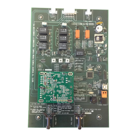
Page 18: Figure 5-1, Det-8Z Main Controller Board
Setup Digitize Inc Figure 5-1, Det-8Z Main Controller Board Qnode Controller Board Q-Node is a microprocessor based central polling controller Buss interface. The Q- Node drives the Multiplex loop, and communicates with the modules along the TBUSS. It communicates with the System 3505 through RS-485 serial port communication. -
Page 19: Setting Transmitter Box Number
5.2 Setting Transmitter Box Number Box Number Definition Each of the Det-8Z transmitters has a separate three digit box number assigned to it. The first digit of the Box Number represents the Track number, settable from 1 to 4. The second and third digits of the Box Number represent the Street that the Transmitter is installed by. -
Page 20: Setting Supervisory Jumpers
J6 and J7 on the Det-8Z transmitter enable and disable the Panel Supervisory feature. The Det-8Z transmitter is capable of monitor the panels to the left and right, and report a trouble condition if the fail to operate properly. See Figure 5-4. -
Page 21: Setting Qnode Number
Digitize Inc. Setup 5.4 Setting Qnode Number The Q-Node can be set to any address from 1-32. The address is stored internally in an EEPROM. It is shipped pre-programmed to address #1. The field should reserve address #1 for use on the last Q-Node. - Page 22 Setup Digitize Inc This page is intentionally blank. 700295-0001 Rev. B 10/21...
-
Page 23: Det-8Z Programming Utility
It allows the firmware and panel settings to be uploaded and downloaded from the Det-8Z panel. The settings can be edited and saved on the laptop computer. The requirements for the Det-8Z Programming Utility are simple; A computer running Windows XP or newer with a USB port. -
Page 24: Operation
Det-8Z Programming Utility Digitize Inc. To start the program, simply double click on the icon. The following screen will appear. 6.3 Operation The Det-8Z Programming Utility allows perform the following tasks on a Det-8Z panel: • Upload firmware to the Det-8Z •... -
Page 25: The File Menu
Det-8Z Programming Utility Digitize Inc. 6.3.1 The File Menu The File Menu pull down tab allows you to Open and Save Det-8Z configurations. Selecting “New” configuration loads all of the default settings for a Det-8Z into the programmer software. 6.3.2 The Transfer Menu The Transfer Menu contains all the routines for uploading and downloading the firmware and the configurations for the Det-8Z. -
Page 26: Editing A Det-8Z Configuration
Once the required configuration has been loaded, the main screen of the programmer will be displayed. 6.3.5 Main Screen Zones (1-6) – The Det-8Z has six input zones. Zone 1 Pull Rope Left Activated when rope on left side of Transmitter pulled. -
Page 27: Zone Settings Window
Det-8Z Programming Utility Digitize Inc. Box Settings – opens a new window for editing various settings common to the entire Det-8Z panel. 6.3.6 Zone Settings Window The Zone Settings Window permits editing settings specific for each of the six zones. -
Page 28: Box Settings Window
Digitize Inc. 6.3.7 Box Settings Window The Box Settings Window permits editing settings common for the entire Det-8Z panel. The upper left corner displays “Box Settings”. Help information for each of the settings is available by clicking the “?” button. Entries for each of the settings are limited to appropriate values. -
Page 29: Uploading Firmware To The Det-8Z
2. Select “Upload Firmware to Panel” from the Transfer Pull down Menu. 3. Select the file containing the firmware you wish to upload to the Det-8Z, the hit “Open”. 4. A new window will open. Press the Reset button on the Det-8Z panel to start the upload. 700295-0001 Rev. B 10/21... - Page 30 Det-8Z Programming Utility Digitize Inc. 5. If the panel and computer connect properly, the upload procedure will begin and the progress will be reported in the window. If the panel and the computer fail to connect, the following window will open. Check the connection of the USB cable and try again.
-
Page 31: Downloading Firmware From The Det-8Z
1. Connect a USB cable from the Det-8Z panel to the laptop computer. 2. Select “Download Firmware from Panel” from the Transfer Pull down Menu. 3. A new window will open. Press the Reset button on the Det-8Z panel to start the download. -
Page 32: Uploading Settings From The Det-8Z
1. Connect a USB cable from the Det-8Z panel to the laptop computer. 2. Select “Upload Settings from Panel” from the Transfer Pull down Menu. 3. A new window will open. Press the Reset button on the Det-8Z panel to start the upload. -
Page 33: Downloading Settings From The Det-8Z
5. The following window signals the successful end of the upload procedure. 6.3.11 Downloading Settings from the Det-8Z 1. Connect a USB cable from the Det-8Z panel to the laptop computer. 2. Select “Download Settings from Panel” from the Transfer Pull down Menu. - Page 34 Det-8Z Programming Utility Digitize Inc. 3. A new window will open. Press the Reset button on the Det-8Z panel to start the download. 4. If the panel and computer connect properly, the download procedure will begin and the progress will be reported in the window.
- Page 35 Det-8Z Programming Utility Digitize Inc. 5. The following window signals the successful end of the download procedure. The Zone Settings and Box Settings now reflect the values downloaded from the Det-8Z. 700295-0001 Rev. B 10/21 6-13...
- Page 36 Det-8Z Programming Utility Digitize Inc. This page is intentionally blank. 6-14 700295-0001 Rev. B 10/21...
-
Page 37: Mux Utility Software
7 Q-Mux Utility Software Chapter 7, Q-Mux Utility Software. The Q-Mux Utility Software can be used to set or change QNode addresses, and reports the status of up to 99 IDM’s. Start-up status data can also be viewed and logged. The Q-Mux Utility Software is launched via the desktop shortcut or the computer’s “Start”... -
Page 38: Programming
Qmux Utility Digitize Inc. NOTE: The BAUD rate default setting is 9600; this setting should not be changed. 7.2 Programming When the utility is launched it will automatically Scan for Nodes. This can be noted in field. If a Node is found, the current Node address will be displayed in the Status the Select Node field. - Page 39 Qmux Utility Digitize Inc. Programming: if desired, the address of the Q-Mux Node can be changed. address assignment cannot be higher than 32. New Node Address: This field can be used to change the address of the Q-Mux Node. The address assignment can be 1-32, but no higher. When a node address has been entered click on the Program Address button.
-
Page 40: Id Status
Qmux Utility Digitize Inc. After clicking on Yes the Node is programmed and the new address is displayed in the Select Node field. Rescan: The Rescan button can be used to establish connection to a Node that has just been connected to the utility. - Page 41 Qmux Utility Digitize Inc. DC Short: The Status indicator for Normal functioning T-Buss or an Abnormal Non functioning Q-Mux Node IDM T-Bus. Green indicates a Normal Functioning T-Buss. Yellow indicates an Abnormal Non functioning T-Buss. The T-Buss has a very high functional.
-
Page 42: Logging Status
Qmux Utility Digitize Inc. Reset Node: This button resets the node; an LED on the Q-Mux Node will flash 5 times. has stopped, the node has been reset. After the flashing 7.4 Logging Status The Logging Status tab is selected to display status changes within nodes. -
Page 43: Link Monitor
Qmux Utility Digitize Inc. The Logging Status can be used to view the activity, status changes on a selected Node and to capture this data to a file on the PC. The .log files can be opened with Notepad, Wordpad or other text editing programs. -
Page 44: Filter Levels
Qmux Utility Digitize Inc. The Q-Mux Node can be programmed activate the on board Beeper, Relay, or both after a programmable time period for a loss of communication to the 3505. Link Fail Period (Seconds): Select a period of time in seconds after which the Beeper or Relay will activate for a loss of communication. -
Page 45: Analog
Qmux Utility Digitize Inc. 7.7 Analog The Analog tab is selected for Special Analog Applications. The analog tab displayed is used for Stress Sensor IDM Input Modules. NOTES: Nodes using the Stress IDM Modules should be set to Max 63 IDM’s. Do not set the Node to Max 99 IDM’s. - Page 46 Qmux Utility Digitize Inc. Lower Alarm Threshold: The Lower Alarm Threshold is the lower analog value of an IDM at which the IDM will be registered as an alarm. 7-10 700295-0001 Rev. B 10/21...
-
Page 47: Operation
8 Operation Chapter 8, Operation covers how the Det-8Z Transmitter operates during normal (quiet) and non-normal (active) situations. 8.1 Normal (Quiet) Operation Det-8Z Transmitter During normal quiescent operation, the Det-8Z Transmitter will be operating on uninterrupted dc power supplied by the station. -
Page 48: Abnormal (Active) Operation
2. No other Det-8Z is actively transmitting on the 100 mA. loop. If the 100 mA. current is not present on the loop, the Det-8Z will turn on the Loop Problem LED and switch to Ground Mode in an attempt to transmit the alarm information. -
Page 49: Panel Trouble Detected
Each Det-8Z can be configured to monitor the Trouble contacts of neighboring Det-8Z panels. If either of the neighboring panels should go into a trouble condition, the Det-8Z will turn on the Panel Trouble LED and transmit the Panel Trouble via the 100 mA. Loop. -
Page 51: Testing The System
9 Testing the System Chapter 9, Testing the System covers the steps for testing the Det-8Z Transmitter to confirm it is functioning properly. It is recommended that the entire system should be completely tested after the Det-8Z Transmitter is installed and placed into service. This test should at a minimum include: •... - Page 52 Testing the System Digitize Inc. This page is intentionally blank. 700295-0001 Rev. B 10/21...
-
Page 53: Maintenance
Confirming all wire connections are proper and tight. ▪ The panel is closed and secured properly. ▪ Confirm that the inputs to the Det-8Z Transmitter continue to report accurate information on System 3505. No other maintenance is required. 700295-0001 Rev. B 10/21... - Page 54 Maintenance Digitize Inc. This page is intentionally blank. 10-2 700295-0001 Rev. B 10/21...
- Page 56 Digitize by telephone or in writing. Buyer will prepay all freight charges to return any products to the repair facility designated by Digitize and include the RMA number on the shipping container. Digitize will, at its option, either repair the defective products or parts or deliver replacements for defective products or parts on an exchange basis to Buyer, freight prepaid to the Buyer.
Need help?
Do you have a question about the Det-8Z and is the answer not in the manual?
Questions and answers