Advertisement
Quick Links
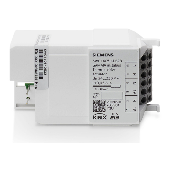
Thermal Drive Actuator RL 605D23, 2 x AC 24...230 V
A6V13488292_en--_a
2023-02-22
The thermal drive actuators are used for controlling electro-thermal actuators
for heating or cooling systems.
●
2 semiconductor outputs for noiseless control of AC 24 V or AC 230 V actuators
●
Maintenance-free terminals for connecting and looping through solid, stranded and
fine-stranded conductors
●
Built-in device for installation in an automation module box AP 118 or room auto-
mation module box AP 641, which has to be ordered separately
Functions for configuration with ETS:
●
With priority control of security and override functions
●
Automatic or demand-based or manual valve flushing
●
Extensive, internal room temperature controllers and ventilation controllers (which
can be assigned freely or for each channel)
●
Powerful calculator modules for weighting temperature values or determining the
largest or a weighted control value
●
Interaction with primary systems for heating demand or cooling demand require-
ments and demand-based pump control
Smart Infrastructure
Advertisement

Related Manuals for Siemens RL 605D23


Summary of Contents for Siemens RL 605D23
- Page 1 Thermal Drive Actuator RL 605D23, 2 x AC 24...230 V The thermal drive actuators are used for controlling electro-thermal actuators for heating or cooling systems. ● 2 semiconductor outputs for noiseless control of AC 24 V or AC 230 V actuators ●...
- Page 2 AC 230 V or AC 24 V actuators per channel or device according to their power consumption. When using Siemens STA/STP actuators, up to 6 (AC 230 V) or up to 3 (AC 24 V) actuators can be controlled per channel.
- Page 3 After bus voltage recovery, wait several seconds before pushing the programming (1) but- ton (not before booting is complete). Activating programming mode a) Briefly press the programming button (1) (< 2 seconds). ð Programming mode is activated. ð The programming LED (2) illuminates continuously. Deactivating programming mode ü...
- Page 4 Behavior on voltage failure/recovery The electronics of the device are bus powered. Therefore, a mains voltage failure only leads to a functional failure of the device if the bus voltage also fails as a result of the main voltage failure. In case of bus voltage failure, the current status and other values for each channel are saved permanently so that they can be restored when the bus voltage is recovered.
- Page 5 Counting of operating hours An operating hours counter can record the operating hours in hours or seconds at the valve output using various evaluation methods. On the one hand, the switch-on processes can be counted when electrical voltage is present at the output, or the time for heating or cooling can be recorded, i.e.
- Page 6 Error messages Diagnostic routine Each channel of the thermal drive actuator detects an overload or a short circuit on the valve outputs. To do this, a diagnostic routine which takes approx. 60 s is executed on both chan- nel outputs. The diagnostic routine can be started in two different ways: ●...
- Page 7 Schematic design of a thermal drive actuator channel 1 bit 8 bit Control value monitoring Error control value Control value limitation Override 1 – 6 ≥ 1 active PWM calculation Valve flushing Valve flushing Valve flushing status start/stop Direct operation Status control value (1 bit) Status control value (8 bit) Status switching...
- Page 8 Technical design Position and function of the connections, operating and display elements Fig. 2: Position and function of the connections and labeling, operating and display elements Pos. Connection, operating or display Function element 1 Connection pins for KNX bus terminal Connect KNX bus. block 2 Programming button Short push of button (<...
- Page 9 Type overview Type Designation Item number Link Thermal drive actuator RL 605D23, 2 x AC 24...230V Scope of delivery Module for installation in AP 118 automation module box or in AP 641 room automation module box. Version of the Engineering Tool Software...
- Page 10 Documents related the product, such as operating and installation instructions, application program description, product database, additional software and CE declarations can be downloaded from the following website: http://www.siemens.com/gamma-td Frequently asked questions For frequently asked questions about the product and their solutions, see: https://support.industry.siemens.com/cs/products?dtp=Faq&mfn=ps&lc=de-WW...
- Page 11 Notes Security The device is designed to be installed in an AP 118 automation module box or in an AP 641 room automation box. CAUTION National safety regulations Failure to comply with national safety regulations may result in personal injury and property damage.
- Page 12 Start-up Connecting thermal actuators to the semiconductor outputs Areas of use The device is installed in an automation module box AP 118 or a room automation module box AP 641 in dry interior spaces. Fig. 3: 0.5...2.5 mm² 2.5 mm² Smart Infrastructure A6V13488292_en--_a GAMMA Instabus 2023-02-22...
- Page 13 Connecting KNX Fig. 4: 0.6…0.8 mm Test of KNX 24 V DC type SELV This test can be used to check whether the bus connection cable is connected with the cor- rect polarity and whether device is supplied with bus voltage. Fig. 5: A very long push of the programming button of more than 20 seconds resets the device to its factory settings.
- Page 14 Number of actuators per channel or device 24 V Number of actuators per channel or device 230 V per channel and device in relation to Siemens STA/STP types - see Accessories Power loss Maximum power loss of the device at rated 0.84 W output...
- Page 15 Protection settings Electrical safety, device fulfills EN 50428 EMC requirements, device complies with EN 50428 Test mark KNX, EAC, RCM, WEEE, China-RoHS CE mark Reliability Failure rate (at 40°C) 227 fit Connection example Fig. 6: CAUTION A common supply voltage for all channels is applied to terminals L1 and N. Each output channel has its own ground terminal.
- Page 16 Dimension drawing Fig. 7: Compliance information FCC Statement WARNING Installation and usage of equipment not in accordance with instructions manual may result in: Radiation of radio frequency energy Interference to radio communications ● Install and use equipment in accordance with installation instructions manual ●...
- Page 17 2. this device must accept any interference received, including interference that may cause undesired operation FCC Caution: Changes or modifications not expressly approved by Siemens Switzerland Ltd. could void the user’s authority to operate the equipment. United States representative https://new.siemens.com/us/en/products/buildingtechnologies/home.html Industry Canada statement This device complies with ISED’s license-exempt RSSs.
- Page 18 Issued by © , 2023 Technical specifications and availability subject to change without notice. Document ID A6V13488292_en--_a Edition 2023-02-22...
Need help?
Do you have a question about the RL 605D23 and is the answer not in the manual?
Questions and answers