Advertisement
s
CA2N3834en_09
2013-06-16
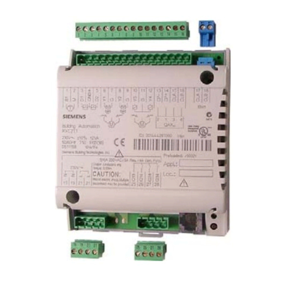
Desigo™ RXC
Room controllers
For fan-coil systems, chilled ceilings and radiators
with L
M
® compatible bus communications
ON
ARK
The RXC20, RXC21 and RXC22 room controllers are used for temperature control
in individual rooms.
For 2-pipe or 4-pipe fan-coil systems, with or without change-over
For chilled ceilings and radiators
Control of AC 24 V PDM
and damper actuators, or electric heating coils
Volt-free relay contacts for fan control and electric heating coils
PI or PID control (depending on application)
Downloadable application software
L
M
® compatible bus communications
ON
ARK
For use in the Desigo building automation and control system
AC 230 V operating voltage
1) PDM = pulse/duration modulated
RXC20.1 / RXC20.5
RXC21.1 / RXC21.5
RXC22.1 / RXC22.5
1)
thermic valve actuators, 3-position AC 24 V valve
3
Building Technologies
834
Advertisement
Table of Contents

Related Manuals for Siemens Desigo RXC21.5


Summarization of Contents
Room Controllers Overview
Product Features
Details applications for fan-coil systems, chilled ceilings, radiators, and LONMARK® bus communications.
Use and Applications
General Use
Details controller applications for fan-coil systems, chilled ceilings, radiators, and general room temperature control.
I/O Module Functionality
Explains using controllers as universal I/O modules with building automation systems for input registration and output control.
Functions and Types
Controller Functions
Functions are determined by the selected application, parameters, and input/output configuration.
Controller Types
Differentiates RXC models based on the number of outputs they provide.
Ordering, Compatibility, and Design
Ordering Information
Specifies how to order controllers, including quantity, product name, type code, and application.
System Compatibility
Lists compatible Siemens devices like QAX room units and other field devices for use with RXC controllers.
Controller Design
Describes the physical components: housing base, cover, PCB, terminals, service LED, and service pin.
Terminal Cover
Explains the optional terminal covers for protecting connection terminals from physical contact and dirt.
Label, Connections, and Communication
Labeling Fields
Explains the use of 'Appl.' and 'Loc.' fields for application and location identification via handwriting or labels.
Connection Terminals
Details detachable plug-in terminals and physical separation for AC 230 V supply and relay outputs.
Cable Restraints
Provides guidance on using cable restraints for AC 230 V terminals and securing conductors with cable ties.
Communication Interfaces
Outlines LONWORKS® bus and PPS2 interfaces for connecting to devices, room units, and service tools.
Bus, Service Indicators, and Disposal
LONWORKS® bus and PPS2 Wiring
Illustrates wiring for LONWORKS® bus, PPS2, and service tools, showing connections with a QAX room unit.
Service LED and Pin
Explains the function of the service LED for status indication and the service pin for controller identification.
Waste Disposal
Advises on proper disposal of electronic waste according to WEEE directive and adherence to local laws.
Engineering Notes
Refers to installation guide CA110334 for LONWORKS® bus topology and cable dimensioning for supply voltage.
Mounting and Commissioning
Supply Cables and Outputs
Details AC 230 V supply cables, volt-free relay outputs, and AC 24 V triac outputs specifications.
Mounting Instructions
Details rail mounting and surface mounting options, including screw size and tightening torque.
Mounting Precautions
Lists important notes for mounting, including accessibility, air circulation, service access, and regulations.
Commissioning Procedure
Explains commissioning with the RXT10 tool and refers to the RXT10 user manual CM110669.
Function Testing
Describes testing controller inputs and outputs using the RXT10 tool before delivery.
Technical Data
Power Supply and Operating Data
Provides details on operating voltage, frequency, power consumption, and control algorithms (PI or PID).
Input and Output Specifications
Details signal inputs, AC 24 V triac outputs, and various relay outputs (Q14, Q24, Q34, Q44).
Interface Specifications
Covers interface types for room units and LONWORKS® bus, including connectable units and baud rates.
Cable Connections and Standards
Cable Connections
Specifies terminal blocks, conductor types, maximum tightening torque, and cable lengths.
Housing Protection Standard
Details protection class IP30 (with cover) and IP20 (without cover) according to EN 60529.
Ambient Conditions
Specifies operating, transport, and storage temperature and humidity ranges.
Standards and Directives
Lists applicable product standards, CE marking, EMC, LVD, RoHS, and UL compliance.
Environmental Compatibility
Provides information on product environmental declaration, RoHS compliance, and ISO standards.
Connection Terminals
RXC20 Terminal Layout
Diagram and list of terminal connections for RXC20, including measured value input, signal, triac, room unit, and power supply.
Tool Socket
Describes the standard RJ45 tool socket for LONWORKS® devices, listing pin assignments.
Connection Terminals (Continued)
RXC21 Terminal Layout
Diagram and list of terminal connections for RXC21, including inputs, outputs, and bus connections.
Connection Terminals (RXC22)
RXC22 Terminal Layout
Diagram and list of terminal connections for RXC22, covering inputs, outputs, and power supply.
Connection Diagrams
Field Device and Power Supply Connections
Illustrates connection diagrams for field devices, room unit, LONWORKS® bus, and power supply for RXC controllers.
Fan and Heating Coil Connections
Details connections for 3-speed fans (Q1), 1-speed fans (Q1.1), and electric heating coils (Q2).
Actuator Connections
Parallel Thermic Actuator Connection
Explains connecting up to 2 thermic actuators directly or using a power amplifier for more.
Mixed Operation Note
Warns against mixed operation of actuators connected to the controller and a power amplifier.
Dimensions and Drilling
Controller Dimensions
Provides dimension diagrams for the controller without and with terminal covers fitted.
Drilling Diagram
Shows the drilling template with key dimensions for surface mounting the room controller.
Need help?
Do you have a question about the Desigo RXC21.5 and is the answer not in the manual?
Questions and answers