Advertisement
Quick Links
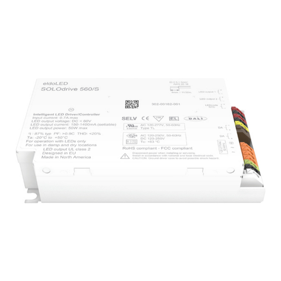
Wiring diagram SOLOdrive 560/S
Pay attention when connecting the LED groups:
polarity reversal results in no light output and often damages the LEDs.
WARNING: Risk of electrical shock. May result in serious injury or death. Disconnect power before servicing or installing.
CAUTION: The device may only be connected and installed by a qualified electrician. All applicable regulations, legislation and build-
ing codes must be observed. Incorrect installation of the device can cause irreparable damage to the device and the connected LEDs.
LED group
Indicates the location of the connectors for your LED groups. These
LED groups represent one DALI ballast.
LED wiring distance
Maximum wiring distance at full load:
20
AWG value
Distance (m)
14
Distance (ft)
45.9
Please observe voltage drop over long cable lengths.
Longer cable lengths increase EMI susceptibility.
120-277 VAC
19
18
17
16
18
22
28
36
59
72.2
91.9
118.1
©
2012 eldoLED. All rights reserved. V1.0
More documentation and eldoLED's terms and conditions are available at www.eldoled.com.
1
2
LEDcode/NTC
LEDcode allows configuration of
• Dimming curve: lin / log
• Minimum dimming level
• NTC throttle temperature
• LED drive current per output: from 200mA-1,050mA in 1mA steps
Programming the driver via LEDcode requires a TOOLbox pro and
FluxTool software.
Connecting a 47kΩ NTC thermistor enables closed loop thermal
control. The NTC throttle temperature is programmable through
LEDcode.
DALI
You can use these connectors to connect the driver to a DALI network.
Always combine a DA+ and DA- connector for either data input or data
output.
120-277 VAC
The driver has been designed for use with universal mains voltage in-
put of 120-277 VAC, 50/60Hz.
(SL0560S1)
AWG 20-16
2
0.5-1.5 mm
9 mm
0.35 inch
Advertisement

Subscribe to Our Youtube Channel
Related Manuals for eldoLED SOLOdrive 560/S


Summary of Contents for eldoLED SOLOdrive 560/S
- Page 1 Always combine a DA+ and DA- connector for either data input or data output. 120-277 VAC The driver has been designed for use with universal mains voltage in- put of 120-277 VAC, 50/60Hz. © 2012 eldoLED. All rights reserved. V1.0 More documentation and eldoLED’s terms and conditions are available at www.eldoled.com.
- Page 2 Europe bv Luchthavenweg 18a 5657 EB Eindhoven The Netherlands T +31 40 2054050 F +31 40 2054058 info@eldoled.com eldoLED America, Inc. 1762 Technology Drive # 226 San Jose, CA95110 T +1 408 451 9333 F +1 408 451 9335 nasales@eldoled.com...
Need help?
Do you have a question about the SOLOdrive 560/S and is the answer not in the manual?
Questions and answers