
Related Manuals for eRapta AYX103


Summary of Contents for eRapta AYX103
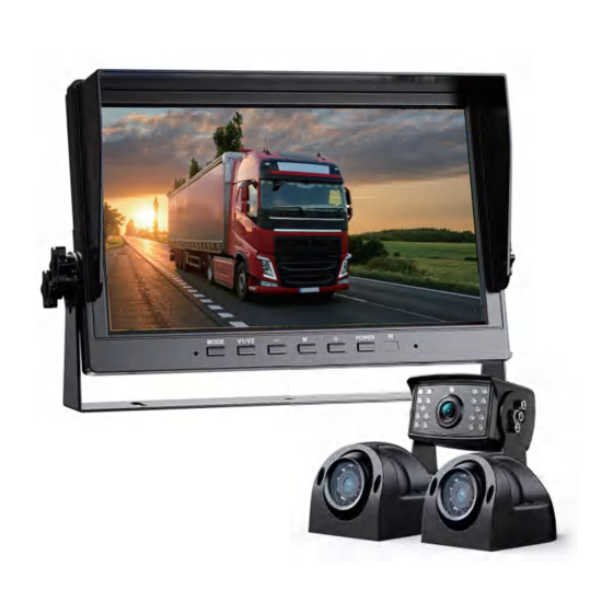
- Page 1 HD Wired 10" Backup Camera System (AYX10 3) Installation and Operation Guide...
- Page 2 We recommend that you retain this guide with the system as a ready reference. If you have any questions, or if you require technical support, sales2@erapta.com please contact us at this email address: We will respond with 24-hours to provide you with the support you require.
-
Page 3: Table Of Contents
TABLE OF CONTENTS 1 WHATS IN THE PACKAGE ................. 1 2 SAFETY PRECAUTIONS ................2 3 SYSTEM DESCRIPTION ................2 3.1 Monitor ..................2 3.2 Camera ................... 5 3.3 Camera Cable ................. 5 3.4 Remote Control ................6 4 SYSTEM INSTALLATION ................6 4.1 Take the Ti m e to Make an Installation Plan ........ -
Page 4: Whats In The Package
1 WHATS IN THE PACKAGE eRapta Congratulations! Our back-up camera system will provide many years of reliable service, because our monitors, cameras and cables are of the highest quality. Please examine the shipping box to see if there are any signs of rough handling. Unpack the box carefully and verify that each item shows no signs of shipping damage. -
Page 5: Safety Precautions
2 SAFETY PRECAUTIONS To operate properly, this back-up system requires the monitor to be connected to a 9-36 Volt Direct Current power source (Current limited 1~2A). To avoid an electric shock injury or damage to the system, we recommend that a qualified technician with appropriate training and experience be obtained to perform this critical connection. - Page 6 3.1.1 SD Card Access Port An SD card access port is located on the top right side of the monitor. The SD card is the primary storage device on the monitor, onto which camera video imagery is captured. You just need to press the memory card hard and it will pop out or get stuck in.
-
Page 7: Camera
As illustrated above, this button allows the user to select various camera screen displays. Pressing the button repeatedly cycles each camera channel display one-by-one, and then it will display a two or four camera channels grouped on the screen(if you turn on a split mode). These single and multiple display options provide the user with great viewing flexibility. -
Page 8: Remote Control
3.1.4 Main Screen Interface Camera 1 : Each display will indicate its CAM# and signal strength in its upper left. REC : Recording video, there will be red REC in upper middle left of display. In the event of SD card issues, re-format the SD card (RECORD menu). -
Page 9: System Installation
4 SYSTEM INSTALLATION The system components are designed to be assembled without difficulty and with simple tools. 4.1 Take the Time to Make an Installation Plan We recommend that that you make plan before you begin the installation of your system components. This approach will eliminate the likelihood of running into problems with cable routing, camera mount locations and power supply. - Page 10 4.2.1 Install the Monitor The monitor is delivered with a metal U-shaped bracket and a Fan-shaped bracket. U-shaped Bracket Installation: 7...
- Page 11 4.2.2 Wiring Schematic Diagram 4.2.3 Power Supply Safety If you are not confident that you can make the following electrical connections safely, then please have these connections completed by a technician. Before connecting the power supply to the system, please ensure that voltage of the battery or power source is 9-36 DC Volts.
- Page 12 Option 1–System is mounted in a Vehicle Option 2–System is mounted in a Static Location such as a bus station monitoring system, site security system, etc wire *The green only triggers the CH2 camera with Parking Lines. And under parking mode, other buttons will be locked and can't be used for safety.
- Page 13 4.2.7 Install the Camera Cable Your plan will define the routing of each of the camera cables. When the cables are being installed, please observe the following procedures: Use light color tape to label each end of the camera cable to mark its designated CH number so that there is no confusion when you connect the cameras and their cables to their respective harness CH sockets.
- Page 14 4.2.9 Connect the Camera Cables to the Monitor 8-pin connector to Monitor 4-Pin Aviation Video Cable Connectors Please exercise care when you connect the cables together. Both the 8-pin harness cable and the 4-pin aviation video cables have pins one end that line up with holes on the other end.
-
Page 15: System Operation
4.2.12 Secure the Cables When the system is set-up the cables may now be properly secured and stowed. Use plastic split-shield cable covers where appropriate to protect the cables in open areas. Secure the cables using adhesive 3M type ¼” cable clips and/or zip ties. -
Page 16: Read Before Use
Software Management System Panels and Sub-panels Logo Main-panels Sub-panels Movie Quality, Movie Clip Time, Movie Off Time, Auto Movie Mode Record, Sound Record, To MoviePlayback Still Capture Still Quality, To PhotoPlayback Clock Settings Set the Year, Month, Day and Time Media Tool Format SD-Card Rotate, Car ACC Line, AHD1 Mirror, AHD2 Mirror, Date... - Page 17 min, 10 min. If you choose “Off”, then the system will keep recording a long video until you stop or power off it. 5.2.3 Movie Off Time This is the time of the system's flameout recording: 0 min, 5 sec, 30 sec, 1 min, 3 min.
-
Page 18: Still Capture Panel
protect the videos; To PreviewMode: the screen can exit it and back to the main panel.) Press UP+ / DOWN-” button to select and press SEL button to confirm. When the video is palying, you can press UP+ / DOWN- button to ... -
Page 19: Media Tool Panel
to previous panel. 5.5 Media Tool Panel 5.5.1 Format SD-Card You can format the SD Card with this function. But please careful and make sure you have saved the important videos to the computer when you use this. 5.6 General Settings Panel 5.6.1 Rotate ... -
Page 20: Language
There are 4 styles to choose from: None, YYYY MM DD, MM DD YYYY, DD MM YYYY. 5.6.5 Stamp There are 4 styles to choose from: Date+Logo, Date, Logo, Off. 5.6.6 LCD Power Save There are 3 options for choose from: Off, 1 min, 3 min. ... -
Page 21: Troubleshooting
4-pin cables to the power cord, and then connect to the cameras, to try again. If there is still no improvement, maybe power cord gets wrong during sales2@erapta.com use, please contact us and we will help you: 6.4 After power-on, the screen still has no picture? ... - Page 22 If you still have problems, please contact us: sales2@erapta.com 6.5 If the monitor shows parking lines and the buttons can’t work? It seems like that the monitor enters parking mode, please disconnect the Green wire for try.
-
Page 23: Warranty
Every message will be replied within 24h. Our contact email is: , you can write it down or add it to your address sales2@erapta.com book. Contact Person: Luis Contact Email: sales2@erapta.com Website: www.eRapta.com 20...
Need help?
Do you have a question about the AYX103 and is the answer not in the manual?
Questions and answers