Sign In
Upload
Manuals
Brands
krom schroeder Manuals
Controller
E8
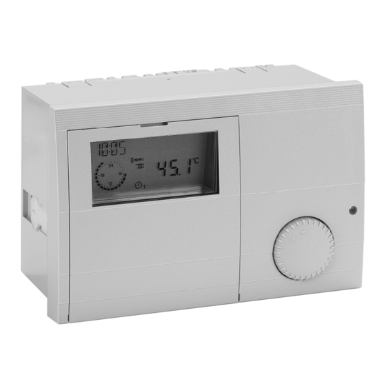
User Manuals: krom schroeder E8 Heating Controller
Manuals and User Guides for krom schroeder E8 Heating Controller. We have
1
krom schroeder E8 Heating Controller manual available for free PDF download: Operating And Installation Instructions
krom schroeder E8 Operating And Installation Instructions (76 pages)
Heating Controller
Brand:
krom schroeder
| Category:
Controller
| Size: 1 MB
Table of Contents
General Information
2
Safety Information
2
Power Connection Regulations
2
Safety
2
Warranty Conditions
2
Important Text Passages
2
Installation
2
Version
2
General Notes
3
Description
3
Declaration of Conformity
3
Function
3
Table of Contents
4
Contents
4
Part 1: Operation
8
Operation in Normal Mode
8
Operating Elements
8
Ç Operating Mode Selection
8
Effect of the Operating Mode
9
Display in Normal Operation
10
Changing the Settings
11
Operating Elements
11
Operating Level
12
Areas
13
General
13
Display
13
Users
13
Time Programs
13
Expert
13
Expert HS (Only for HS Via Ebus)
13
Levels
13
Installation
13
Hot-Water
13
Part 2: Overview of Display Values and Settings
14
General Area
14
Date/Time/Holiday
14
Service
16
Code Number Entry
16
Relay Test
16
Sensor Test
17
Sw no XXX-XX
18
HS MANUAL (Only with Code No.)
18
Limiter Test XX,X°C
18
Service
19
Reset
19
Display Range
20
Installation
20
T-Outside
20
T-Hs des
20
T-Hs
20
MOD DEPTH (Only in the Case of HS Via Ebus Connection)
20
Temperature of the Multifunction Relay
20
T-Buffer B
21
Heating Circuit I / II
22
T-DHW B (Storage Tank Lower Temperature)
22
T-ROOM des a (Current Value for Set Room Temperature)
22
T-ROOM (Room Temperature)
22
User Area
23
Installation
23
GERMAN => Language
23
Contrast
23
Display Sel
23
Select Prog
23
Hot Water
24
DHW (1X Hot Water)
24
T-Dhw 1 - 3 des
24
(Hot Water Temperature Setting)
24
BOB-VALUE (Operation Without Burner)
24
CIRCL-P-DHW (Circulation with Hot Water)
24
ANTILEGION (Hot Water Short Time Heating Function)
24
Heating Circuit I / II
25
Mode
25
T-Room des
25
T-Reduced
25
T-Absence
25
T-LIMIT DAY/T-LIMIT N (Day/Night)
26
Heatslope
26
ADAPTION (Heat Slope Adaption)
27
ROOM INFL (Room Sensor Influence)
27
T-ROOM ADJ (Room Sensor Adaptation)
27
OPT HEAT up (Heating Optimisation)
28
MAX-OPT-TIME (Maximum Bring-Forward)
28
OPT REDUCED (Reduction Optimisation)
28
Pc-Enable
28
Return
28
Timer Program Area
29
List of Available Time Programs
29
Selecting a Timer Program
29
Timer/Heating Program Adjustment
30
Expert Area
33
Installation
33
Code-No
33
Bus-ID Hs
33
BUS ID1 / 2 (Heating Circuit Number)
33
Bus Termin
34
EBUS SUPPLY (Supply for Ebus)
34
AF SUPPLY (Outdoor Sensor Power Supply)
34
Time Master
34
RESET TIME (Resetting Time for I-Controller)
34
Max T-Hs
35
(Maximum Heat Generator Temperature)
35
Min T-Hs
35
(Minimal Heat Generator Temperature)
35
T-WARM up (Warm-Up Relief)
35
MIN-DELIMI (Minimum Limit Heat Generator)
35
HYSTERESIS (Dynamic Switching Hysteresis)
36
HYST TIME (Hysteresis Time)
36
Operation with Two-Stage Heat Generators or
36
LOCK TIME (Blocking Time 2. Burner Stage)
36
HYST BURNER 2 (Hysteresis 2. Burner Stage)
36
SEQUENCE CHANGE(Time for Switching HS)
37
HS COOL-FCT (Cooling Function for the Heat Generator)
37
T-HS COOL (Start Temperature for Cooling)
37
Auxiliary Relay Functions
38
FUNC RELAY 1 (Function Selection Relay 1)
38
T-MF1 (Switching Temperature Relay 1)
38
HYST MF 1 (Hysteresis Relay 1)
38
FUNC RELAY 2 (Function Selection Relay 2)
40
Screed Program
42
SCREED (Activation of Screed Drying Process)
42
SCREED PROGR (Program Setting)
42
Hot Water
43
DHW RELIEF(Charge Pump Lock)
43
PARALLEL DHW (Pump Parallel Running)
43
T-Hs Dhw
43
Therm Input
43
During Hot Water Preparation)
44
HYST DHW (Hot Water Charging Hysteresis)
44
DHW FOLLOWUP (Pump Run-Down Time)
44
(Storage Tank with Thermostat)
44
WALL HUNG (for Modulating HG)
44
Load through
45
Heating Circuit I / II
46
Hc Function
46
(Heating Circuit Function Selection)
46
PUMP MODE (Pump Operating Mode)
47
Mixer Open
48
(Mixer Dynamics When Opening)
48
MIXER CLOSED (Mixer Dynamics When Closing)
48
MAX T-FLOW(Maximum Flow Temperature)
48
MIN T-FLOW(Minimum Flow Temperature)
48
T-Frost Prot
48
(Frost Protection Temperature)
48
T-OUT DELAY (Outside Temperature Delay)
49
SLOPE OFFSET (Heating Slope Distance)
49
B-HEAT SINK (Circuit Enable)
49
Part 3: General Function Description
50
Heat Circuit Control
50
Weather-Dependent Control
50
Room Sensor Influence
50
Hot Water Generation
50
Frost Protection Function
50
Ebus Burner Controls
51
EEPROM Check
52
Circulation Pump Control
52
Switched According to Heating Requirement
52
Delayed Pump Switch-Off
52
Pump Blocking Protection
52
Mixer Motor Blocking Protection
52
Part 4: Installation and Start-Up
53
Installation
53
Assembly / Dismantling
53
Connecting Instructions
54
Notes on Connecting Heat Generators Via the CAN BUS (also with Coco, E.g. CAN/OT)
54
System Diagram
56
System Diagram with HS Via Ebus
57
Electrical Connection
58
Version 1
58
Power Terminal Assignments
60
Sensor Terminal Assignments
61
Remote Controls
63
The Operator Module Merlin BM, BM 8, and Lago FB
63
Remote Control FBR2
63
Sensor Resistances FBR
64
DCF Receiver
64
Maximum Delimiter
65
Telephone Switch
65
Sensor Values / Characteristic Curve
66
Sensors
67
Outside Sensor AF (AFS) S
67
Immersion Sensor KF (KFS) H/ SPF (SPFS) F
67
Commissioning
68
Commissioning Procedure
68
System Bus
69
The Heating System
69
Bus ID
69
Error Messages
70
Troubleshooting
71
Dimensions
73
Technical Data
74
Glossary
75
Advertisement
Advertisement
Related Products
krom schroeder DG smart
krom schroeder DGS
krom schroeder FCU 505
krom schroeder IC 20
krom schroeder IC 40
krom schroeder TC
krom schroeder TC 1
krom schroeder TC 2
krom schroeder TC 3
krom schroeder TC 4
krom schroeder Categories
Control Unit
Controller
Switch
Security Sensors
Burner
More krom schroeder Manuals
Login
Sign In
OR
Sign in with Facebook
Sign in with Google
Upload manual
Upload from disk
Upload from URL