Unigas TP1030 Manual
Hide thumbs
Also See for TP1030:
- Installation, user's, and maintenance manual (60 pages) ,
- Manual (108 pages)

Subscribe to Our Youtube Channel
Related Manuals for Unigas TP1030


Summary of Contents for Unigas TP1030
- Page 1 TP1030 TP1050 TP1080 Gas burners MANUAL OF INSTALLATION - USE - MAINTENANCE BURNERS - BRUCIATORI - BRULERS - BRENNER - QUEMADORES - ГОРЕЛКИ M039168CD 0.0 10/2019...
-
Page 2: General Introduction
DANGERS, WARNINGS AND NOTES OF CAUTION THIS MANUAL IS SUPPLIED AS AN INTEGRAL AND ESSENTIAL PART OF THE PRODUCT AND MUST BE DELIVERED TO THE USER. INFORMATION INCLUDED IN THIS SECTION ARE DEDICATED BOTH TO THE USER AND TO PERSONNEL FOLLOWING PRODUCT INSTALLATION AND MAINTENANCE. -
Page 3: Directives And Standards
3b) FIRING WITH GAS, LIGHT OIL OR OTHER FUELS DIRECTIVES AND STANDARDS Gas burners GENERAL European directives The burner shall be installed by qualified personnel and in compliance -Regulation 2016/426/UE (appliances burning gaseous fuels) with regulations and provisions in force; wrong installation can cause -2014/35/UE (Low Tension Directive) injuries to people and animals, or damage to property, for which the -2014/30/UE (Electromagnetic compatibility Directive) -
Page 4: Symbols Used
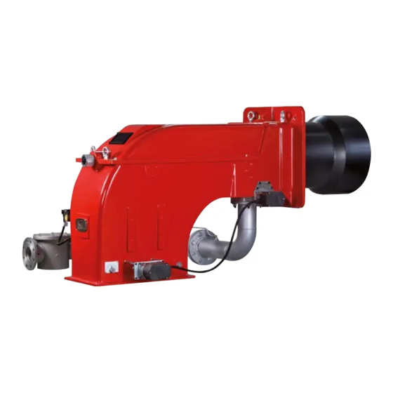
Burner data plate Type Model Gas - Light oil burners For the following information, please refer to Year European Directives the data plate: S.Number -Regulation 2016/426/UE (appliances burning gaseous fuels) Output burner type and burner model: must be Oil Flow -2014/35/UE (Low Tension Directive) reported in any communication with the Fuel... - Page 5 PART I: SPECIFICATIONS PART I: SPECIFICATIONS BURNERS FEATURES This series of industrial burners is designed for all those applications that require big-sized air fans or air-flue heat exchangers to be installed in sound-proof areas to reduce noise. They can be provided with built-in or separate-mounted control panel (console or wall- mounted).
- Page 6 Technical Dpt. Data requested: furnace input; air temperature Power output diagram at 15àC air temperature altitude generator pressure or temperature TP1050 TP1030 TP525A TP520A TP515A TP512A TP93A Example: TP92A furnace input: 9600kW TP91A air temperature: 15°C ...
-
Page 7: Burner Type
Burners are identified by burner type and model. Burner model identification is described as follows. Type TP1030 Model M-. PR. (1) BURNER TYPE TP1030 - TP1050 - TP1080 (2) FUEL M - Natural gas (3) OPERATION (Available versions) PR - Progressive... - Page 8 Overall dimensions (mm) Air inlet flange Boiler drilling plate Burner flange TP1030 1864 544 1320 348 1898 1301 1000 460 936 200 587 1092 322 1175 372 TP1030 100 1864 544 1320 348 1914 1317 1000 460 842 200 587 1092 382 1175 372...
-
Page 9: Performance Curves
PART I: SPECIFICATIONS Performance curves TP1030 TP1050 TP1080 Performance range To get the input in kcal/h, multiply value in kW by 860. Data are referred to standard conditions: 1013mbar, 15°C. - Page 10 PART I: SPECIFICATIONS Pressure in the network / gas rate curves TP1030 DN80 DN100 1 50 1 00 DN125 1 000 1 1 00 1 200 1 300 1 400 Gas rate Stm TP1050 DN80 DN100 DN125 1 00 1 000...
- Page 11 Packing The burners are despatched in wooden crates whose dimensions are: TP1030 - TP1050: 2180mm x 1580mm x 1210mm (L x P x H) TP1080: 2180mm x 1580mm x 1560mm (L x P x H) Packing cases of this type are affected by humidity and are not suitable for stacking.
-
Page 12: Fan Installation
PART II: INSTALLATION Fitting the burner to the boiler To perform the installation, it is necessary to drill the boiler door as described on paragraph “Overall dimensions”; screw the studbolts (5) on the boiler door, according to the drilling plate (see paragraph “Overall dimensions”); move the burner towards the boiler: lift the burner by means of the eyebolts placed on its top side;... - Page 13 PART II: INSTALLATION GAS TRAIN CONNECTIONS The diagrams show the components of the gas trai included in the delivery and which must be fitted by the installer.The diagrams are in compliance with the current laws. ATTENTION: BEFORE EXECUTING THE CONNECTIONS TO THE GAS PIPE NETWORK, BE SURE THAT THE MANUAL CUTOFF VALVES ARE CLOSED.
- Page 14 PART II: INSTALLATION Pilot burner mounting The pilot gas train is already installed to the burner, the following connections must be executed: connection from the filter with stabiliser to the gas supply network connection from the valve to the main gas train, by means of the pipe provided with the burner. ...
- Page 15 PART II: INSTALLATION MultiBloc MBE Actuator VD-V Actuator VD-R Gas filter PS pressure Pressure switch PG min sensor Leakage pressure switch Valve body VB Pressure switch PG max Fig. 3Example of gas train MBE To mount the gas train, proceed as follows: 1-a) in case of threaded joints: use proper seals according to the gas used;...
- Page 16 PART II: INSTALLATION Mounting VD-R & PS-... Actuator VD-R Actuator VD-V 1. Gas pressure regulation is possible with VD-R and PS pressure sensor only. WARNING!!!!. For US/CN installation, the output pressure must be monitoried by min. and max. pressure switches set to +/- 20% of the setpoint. 2.
- Page 17 PART II: INSTALLATION Siemens VGD20.. e VGD40.. Siemens VGD20.. and VGD40.. gas valves - with SKP2.. (pressure governor) - Connect the reference gas pipe (TP in figure; 8mm-external size pipe supplied loose), to the gas pressure nipples placed on the gas pipe, downstream the gas valves: gas pressure must be measured at a distance that must be at least 5 times the pipe size.
-
Page 18: Gas Operation
PART III: MAINTENANCE PART III: MAINTENANCE OPERATION ATTENTION: before starting the burner up, be sure that the manual cutoff valves are open and check that the pressure upstream the gas train complies the value quoted on paragraph “Technical specifications”. Read care- fully the “WARNINGS”... -
Page 19: Adjustment Procedure
PART III: MAINTENANCE Adjustment procedure mensions Dimensions in mm 60° SQM4... 30° 20° Actuator cams (Siemens SQM40) 10° High flame 0° Stand-by MAN - AUTO Low flame - gas 90° Ignition - gas To change the burner setting during the testing in the plant, follow the next procedure. Before starting the burner up, drive the high flame actuator microswitch matching the low flame one (in order to let the burner ope- rates at the lowest output) to safely achieve the high flame stage. - Page 20 PART III: MAINTENANCE head position “MAX”head position Attention! if it is necessary to change the head position, repeat the air and gas adjustments described above. 11 the air and gas rate are now adjusted at the maximum power stage, go on with the point to point adjustement on the SV adjusting cam as to reach the minimum output point.
-
Page 21: Pressure Taps
PART III: MAINTENANCE Regulation VD-R whith PS Setting scale is „Not“ linear! Various sensors available. Output pressure according to sensor‘s measuring range. Increasing pressure Adjust the outlet pressure to the value specified by the burner or equipment manufacturer! While making outlet pressure adjustments, do not exceed a value that creates a hazardous condition to the burner! Decreasing pressure... - Page 22 PART III: MAINTENANCE Collagamento del pilota alla valvola MBE raccordo per attaccarsi alla valvola MBE (con sigilla filetti) fornito a corredo Vite di bloccaggio G1/8” ISO 228...
- Page 23 PART III: MAINTENANCE Calibration air and gas pressure switches The air pressure switch locks the control box if the air pressure is not the one requested. If it happens, unlock the burner by means of the control box unlock pushbutton, placed on the bur- ner control panel.
- Page 24 PART III: MAINTENANCE Adjusting the combustion head Attention! if it is necessary to change the head position, repeat the air and fuel adjustments described above. Only if necessary, change the combusiton head position: to let the burner operate at a lower output, loose the VB screw and move pro- gressively back the combustion head towards the MIN position, by turning clockwise the VRT ring nut.
- Page 25 PART III: MAINTENANCE Center head holes gas flow regulation (natural gas burners) To adjust the gas flow, partially close the holes, as follows: loosen the three V screws that fix the adjusting plate D; insert a screwdriver on the adjusting plate notches and let it move CW/CCW as to open/close the holes; once the adjustmet is performed, fasten the V screws.
- Page 26 PART III: MAINTENANCE...
-
Page 27: Routine Maintenance
PART IV: MAINTENANCE PART IV: MAINTENANCE WARNING: ALL OPERATIONS ON THE BURNER MUST BE CARRIED OUT WITH THE MAINS DISCONNECTED AND THE FUEL MANAUL CUTOFF VALVES CLOSED! ATTENTION: READ CAREFULLY THE “WARNINGS” CHAPTER AT THE BEGINNIG OF THIS MANUAL. At least once a year carry out the maintenance operations listed below. In the case of seasonal servicing, it is recommended to carry out the maintenance at the end of each heating season;... - Page 28 PART IV: MAINTENANCE MultiBloc MBE MultiBloc VD Mounting to push position 1. Position VD on VB, fig. 2+3. 2. Slide VD forward up to the stop, fig. 4. 3. Screw VD on with 2 M5 screws for each, max. 5 Nm/44 in.-lb., fig. 5/6. 4.
-
Page 29: Adjusting The Ignition Electrode
PART IV: MAINTENANCE Adjusting the ignition electrode ATTENTION: avoid the electrode to get in touch with metallic parts (blast tube, head, etc.), otherwise the boiler operation would be compromised. Check the electrode position after any intervention on the combustion head. Fig. - Page 30 PART IV: MAINTENANCE Fig. 4 Replacing the ignition electrode ATTENTION: avoid the electrode to get in touch with metallic parts (blast tube, head, etc.), otherwise the boiler operation would be compromised. Check the electrode position after any intervention on the combustion head. To replace the ignition electrode, proceed as follows: remove the burner cover disconnect the electrode (E) cable (CE);...
- Page 31 PART IV: MAINTENANCE replace the combustion head. Checking the detection current with electrode (natural gas) To check the detection signal follow the scheme in the picture below. If the signal is less than the value indicated, check the position of the detection electrode or detector, the electrical contacts and, if necessary, replace the electrode or the detector.
-
Page 32: Seasonal Stop
PART IV: MAINTENANCE Burner service term - In optimal operating conditions, and with preventive maintenance, the burner can last up to 20 years. - Upon expiry of the burner service term, it is necessary to carry out a technical diagnosis and, if necessary, an overall repair. - The burner status is considered to be at its limit if it is technically impossible to continue using it due to non-compliance with safety requirements or a decrease in performance. - Page 33 PART IV: MAINTENANCE TROUBLESHOOTNG GUIDE - Gas operation * No electric power supply * Wait until power supply is back * Main switch open * Close the switch * Thermostats open * Check set points and thermostat connections * Bad thermostat set point or broken thermostat * Set or replace the thermostat * No gas pressure * Restore gas pressure...
- Page 36 C.I.B. UNIGAS S.p.A. Via L.Galvani, 9 - 35011 Campodarsego (PD) - ITALY Tel. +39 049 9200944 - Fax +39 049 9200945/9201269 web site: www.cibunigas.it - e-mail: cibunigas@cibunigas.it Note: specifications and data subject to change. Errors and omissions excepted.
- Page 37 LME73.000Ax + PME73.831AxBC LME73.831AxBC Service instruction manual M12921CB Rel.1.2 02/2016...
-
Page 38: General Features
GENERAL FEATURES LME/ is suitable for gas, light and heavy oil burners LME7 series has two devices: LME73.000 (hardware) and PME73.831AxBC (programmable unit). The LME73.831AxBC is also available: it has a built in software and it isa not programmable. LME7 is inside the control panel. If supplied, PME73.831BC is inside the LME7; The display AZL23.. -
Page 39: User Interface
User interface : Button A - Display preset output - In lockout position: Power value to the time of fault Info and Enter button - Reset in the event of fault, changeover visual diagnostic of the cause of fault (refer to chapter Diagnostics of cause of fault ) - button - Display flame signal current 2 or phases display - In lockout position: MMI phase to the time of fault... - Page 40 List of phase display on board LME : Phase number of Function 7-segment display Standby Standby, waiting for heat demand Mains ON / test phase (e.g. detector test) Startup Yellow Safety valve ON, air pressure switch test / POC test (timeout / locking Yellow Fan motor ON / air pressure switch test / settling time Yellow...
- Page 41 Operation : The lockout reset button (info button) (EK) is the key operating element for resetting the burner control and for activating / deactivating the diagnostics functions. The multicolor signal lamp (LED) is the key indicating element for visual diagnostics. Both lockout reset button (EK) and signal lamp (LED) are located in the control panel.
-
Page 42: Program Sequence
Program sequence : Version 1: • Ignition load < low-fire • Prepurging in high-fire • Parameter 515 = 1 (condition parameter 259.01 > 0 seconds) - Page 43 Program sequence : Version 2: • Ignition load > low-fire • Prepurging in high-fire • Parameter 515 = 1 (condition parameter 259.01 = 0 seconds)
- Page 44 Phase Function number Lockout phase Standby, waiting for heat demand Operation, modulating operation Interval until release of load controller target (analog or 3-position step input) Under voltage Safety loop open Extraneous light on burner startup (timeout/locking after 30 seconds) Mains ON/test phase (e.g. detector test) Shutdown, actuator opens in CLOSE position (homerun) Safety valve ON, air pressure switch OFF, actuator opens in CLOSE position Part 1: Fan motor ON...
- Page 45 Error code table : Red blink code of fault signal lamp (LED) Possible cause 2 x blinks No establishment of flame at the end of the safety time (TSA) - Faulty or soiled flame detector - Faulty or soiled fuel valves - Poor adjustment of burner, no fuel - Faulty ignition equipment 3 x blinks...
- Page 46 Flame detection – detection electrode : Short-circuit current Max. AC 1 mA Required detector current Min. DC 2 μA, display approx. 45 % Possible detector current Max. DC 3 μA, display approx. 100 % Permissible length of detector cable (laid separately) 30 m (core-earth 100 pF/m) Measuring circuit Keys...
- Page 47 Gas proving system : Valve proving is dependent on input valve proving ON / OFF (X2-02). When a leak is detected, the gas valve proving function ensures that the gas valves will not be opened and that ignition will not be switched on. Lockout will be initiated. Valve proving with separate pressure switch (P LT) Step 1: td4 –...
- Page 48 Instruction, control and modify via AZL2x : The AZL2x.. display/programming unit is shown below: The keys functions are the following: Key F + A While pressing the two keys contemporarly, the code message will appear: by entering the proper password it is possible to access the Service mode. Info and Enter keys Used for Info and Service menues Used as Enter key in the setting modes...
- Page 49 The display will show these data: Lock+unlock codes Flame Open valves Ignition transformers energised Fan motor energised Oil pre-heater energised Plant heat request Parameter setting mode Info mode Service mode Closing actuator Opening actuator Unit measure While pushing the button together with whatever else button, LME73 locks out; the display shows On stand-by position, appears On operation, all the phases appears with their number.
- Page 50 List of phase with display AZL2x : Phase number Function Standby Standby, waiting for heat request Ph08 Power ON / test phase (e.g. detector test) Startup Ph21 Safety valve ON, air pressure switch test / POC test (timeout / locking after 5 seconds), actuator opens in low-fire position / CLOSE position Ph22 Fan motor ON or air pressure switch test / settling time...
- Page 51 Error code list with operation via internal AZL : Error code Clear text Possible cause Loc 2 No establishment of flame at the - Faulty or soiled fuel valves end of the safety time (TSA) - Faulty or soiled flame detector - Poor adjustment of burner, no fuel - Faulty ignition equipment Loc 3...
- Page 52 Entering the Parameter levels: y means of a proper use of the keys, it is possible to enter the various level parameters, as shown in the following flow chart :...
- Page 53 Info level : Keep pushing the button until appears. Use + or - for scrolling the parameter list. If on the right side a dash-dot appears, it means the display doesn't show the full description. Push again for 1 to 3 s in order to show the full description. Below the visible Info parameters: Parameter Parameter list...
- Page 54 Service level : Keep pushing the button until appears. Use + or - for scrolling the parameter list. . If on the right side a dash-dot appears, it means the display doesn't show the full description. Push again for 1 to 3 s in order to show the full description. Below the visible Info parameters: Parameter Parameter list...
- Page 55 Process data Normalized speed Read only 100% 0.01 % Service Mains voltage Read only LME73.000A1: Service 175 V LME73.000A2: 350 V Flame intensity Read only 100% Service...
- Page 56 Parameter level (Heating engeneering) : This level lets the engineer to modify some burner parameters. It is protect with a 4 digit password (SO level) and a 5 digit password (OEM level) Password input : push F and A buttons together until the display shows "code" and 7 underlines. The left one flashes. By move the flashing underline until it is on the desired position and push "enter".
- Page 57 Repetition in the event of loss of flame during operation Edit 0 SO 0 = None 1 = None 2 = 1 x Repetition 241.00 Valve proving Edit 1 SO 0 = Off 1 = On 241.01 Valve proving Edit 0 SO 0 = During prepurge time (t1) 1 = During postpurge time (t8)
- Page 58 Power setting Analog input (feedback potentiometer ASZxx.3x required) Edit 0 SO 0 = 3-position step input 1 = 0...10 V 2 = 0...135 Ω 3 = 0...20 mA 4 = 4...20 mA with lockout at I <4 mA 5 = 4...20 mA WARNING Parameter Num.
- Page 60 Note: Specifications and data subject to change. Errors and omissions excepted.
Need help?
Do you have a question about the TP1030 and is the answer not in the manual?
Questions and answers