
Related Manuals for Vmac H400011


Summary of Contents for Vmac H400011
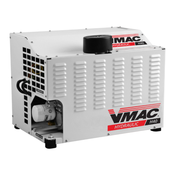
- Page 1 ® Hydraulic Driven Air Compressor Installation and Owner’s Manual (Includes Service Instructions) H400011 | H600011 Closed Center Hydraulic Systems www.vmacair.com...
-
Page 3: Table Of Contents
Accessory Products from VMAC ........ - Page 4 Copyright © 2023 VMAC Global Technology Inc. All Rights Reserved. These materials are provided by VMAC for informational purposes only, without representation or warranty of any kind, and VMAC shall not be liable for errors or omissions with respect to the materials. The only warranties for VMAC...
-
Page 5: General Information
The procedures described in this manual are the only approved methods of service and operation. Ordering Parts To order parts, contact a VMAC dealer. The dealer will ask for the VMAC System ID (see page 35), part number, description and quantity. Locate the nearest dealer online at www.vmacair.com/dealer-locator or call 1-877-912-6605. -
Page 6: Safety
VMAC will not be held responsible for any liability, consequential damages, injuries, loss or damage to individuals or to equipment as a result of the failure of anyone to properly adhere to the procedures set out in this manual or standard safety practices. -
Page 7: Safety Precautions
Proper service and repair are important to the safety of the service technician and the safe, reliable operation of the equipment. Always use genuine VMAC replacement parts. The procedures described in this service manual are effective methods of service and repair. - Page 8 • Do not operate the compressor without guards in place. If the guards are damaged or missing, replace them before operating the equipment. VMAC - Vehicle Mounted Air Compressors VMAC Technical Support: 888-241-2289 VMAC Knowledge Base: kb.vmacair.com...
- Page 9 Never adjust or attempt to make any repairs to the compressor system while the hydraulic circuit is pressurized. Components and hoses under pressure could fail and cause serious injury or death. VMAC - Vehicle Mounted Air Compressors VMAC Technical Support: 888-241-2289 VMAC Knowledge Base: kb.vmacair.com...
-
Page 10: Warranty
(ii) services are completed in accordance with the Owner’s Manual; (iii) proof of purchase of applicable service kits are made available to VMAC upon request. The VMAC Lifetime Warranty is applicable to new products shipped on or after 1 October, 2015. Warranty Registration The VMAC warranty registration form is located near the back of this manual. - Page 11 If requested, failed parts must be returned to VMAC for evaluation. 4) Dealers may login to the VMAC website to view the "VMAC Labour Time Guide" (under “Agreements”) to see the allowable warranty labour times. 5) Warranty invoices must include the Service Ticket number, VMAC System ID#, hours on the compressor, and a detailed description of the work performed.
-
Page 13: Hydraulic Driven Air Compressor Installation Manual
® Hydraulic Driven Air Compressor Installation Manual... -
Page 15: Installation Considerations
Driven Air Compressor system to operate erratically. Prior to installing the system, consider the following factors: • For proper operation, VMAC’s Hydraulic Driven Air Compressor Systems require proper hydraulic pressure and flow, ensure the hydraulic circuit is designed with these requirements in mind (see page 17). -
Page 16: Mounting Locations And Ventilation
Ensure adequate ventilation is provided for cooling and to evacuate the heat generated by the unit. If mounting in an enclosure, VMAC strongly recommends mounting the unit on a pullout drawer and extending the drawer any time the unit is run. - Page 17 Recommended Component Layout Battery Fuse Ignition switched relay Hydraulic Driven Air Compressor Display Box (mounted inside weather proof enclosure) Figure 2 — Recommended component layout VMAC - Vehicle Mounted Air Compressors VMAC Technical Support: 888-241-2289 VMAC Knowledge Base: kb.vmacair.com...
-
Page 18: Speed Control
Hydraulic Driven Air Compressor will signal the PTO to set hydraulic flow to the minimum desired cfm. “Speed 2” is activated to signal the PTO to increase hydraulic flow to provide the maximum cfm (or speed system warm up). VMAC - Vehicle Mounted Air Compressors VMAC Technical Support: 888-241-2289 VMAC Knowledge Base: kb.vmacair.com... -
Page 19: Hydraulic Requirements
Hydraulic Requirements This VMAC Hydraulic Driven Air Compressor is designed to be driven by a load sensing pressure compensated variable displacement hydraulic pump. VMAC is unable to provide hydraulic circuit designs or consult on specific hydraulic installations. We recommend working with a local hydraulic expert to design and/or install the hydraulic circuit that will power the Hydraulic Driven Air Compressor system. - Page 20 Hydraulic Driven Air Compressor system. If this system is being installed in a shared hydraulic circuit, the use of a shut off valve is advised. VMAC - Vehicle Mounted Air Compressors VMAC Technical Support: 888-241-2289 VMAC Knowledge Base: kb.vmacair.com...
-
Page 21: Hydraulic Fluid And Line Sizing Recommendations
Hydraulic Fluid and Line Sizing Recommendations VMAC is unable to provide hydraulic circuit designs or consult on specific hydraulic installations. We recommend working with a local hydraulic expert to design and/or install the hydraulic circuit that will power the Hydraulic Driven Air Compressor system. - Page 22 The following information provides specific line sizing recommendations for mobile hydraulic system installations intended for use with VMAC’s Hydraulic Driven Air Compressor systems. The dimensions provided indicate “inside diameter” (ID). Supply Line Sizing Failure to use the correct suction line size may result in hydraulic pump cavitation leading to premature pump failure.
- Page 23 Table 5 — Temperate climate Pressure and Return Line Sizing Pressure Line Size Return Line Size 3/4 in 1 in Table 6 — Pressure and return line size VMAC - Vehicle Mounted Air Compressors VMAC Technical Support: 888-241-2289 VMAC Knowledge Base: kb.vmacair.com...
-
Page 24: Hydraulic Driven Air Compressor Harness Reference
+ 12 V. 4 (30) System Power Display Box Colour Function Notes Pink VCAN Hi VMAC CAN Bus (twisted pair with pin 2). Dark VCAN Low VMAC CAN Bus (twisted pair with pin 1). Blue Green Display GND Ground. Display + 12 V + 12 V. - Page 25 Heater Solenoid Colour Function Notes Switched + 12 V + 12 V ON, 0 V OFF Blue Green Ground 0 Ω Table 7 — Harness reference chart VMAC - Vehicle Mounted Air Compressors VMAC Technical Support: 888-241-2289 VMAC Knowledge Base: kb.vmacair.com...
-
Page 26: Upfitter Electrical Requirements
Failure to adhere to these recommendations will cause the Hydraulic Driven Air Compressor system to operate erratically. VMAC’s Hydraulic Driven Air Compressor systems require a steady 20 A at 12 V dc (nominal) to operate. A 30 A fuse or circuit breaker is recommended. - Page 27 Electrical Schematic Figure 4 — Electrical schematic VMAC - Vehicle Mounted Air Compressors VMAC Technical Support: 888-241-2289 VMAC Knowledge Base: kb.vmacair.com...
-
Page 28: Installing The Hydraulic Driven Air Compressor System
(i.e. air receiver tank, hose reel, etc.). ☐ Mount the unit (Figure 5). • If using the VMAC Mounting Brackets (P/N: A700140), install them now. • If using the integral mounts, drill (×4) 13/32 in holes in the selected mounting location. -
Page 29: Telematics Integration
"Hydraulic Driven Air Compressor Harness Reference" on page 22. Ensure both systems share a good ground. Program the telematics system to interpret VCAN messages (custom VMAC PGNs). 4) Apply power to the Hydraulic system and observe the telematics data (data will be present if the system is powered, regardless of whether the system is running or not). -
Page 30: Testing The Installation
Testing" on page 81) into the hydraulic circuit at the supply line to the Hydraulic Driven Air Compressor to confirm actual hydraulic flow. ☐ Install the VMAC Air Test Tool (A700152) with the appropriate orifice and the ball valve closed. If the unit is vehicle mounted, ensure the vehicle is parked on level ground, the transmission is in “PARK”, with the parking brake... - Page 31 “Speed 1” does not drop below the minimum requirement. ☐ Open the ball valve on the VMAC Air Test Tool (if not using the VMAC Air test tool with the proper orifice, open the ball valve enough to maintain 100 psi) and operate the system for at least 1 hour at full load while monitoring the hydraulic flow and cfm output.
-
Page 32: Performance Testing And System Adjustments
Compressor Performance Testing System operation can be tested using the tools that will be operated by the system or by using the VMAC Test Tool (A700052) with the appropriate orifice in the outlet to simulate tool use (Figure 6). Ball valve... - Page 33 The system will continue to monitor temperature and air pressure and will restart as needed to maintain operating parameters. VMAC - Vehicle Mounted Air Compressors VMAC Technical Support: 888-241-2289 VMAC Knowledge Base: kb.vmacair.com...
-
Page 35: Hydraulic Driven Air Compressor Owner's Manual
® Hydraulic Driven Air Compressor Owner’s Manual... -
Page 37: Identifying Your System
(Figure 8). H600011 A BC 123 Model number Unique identifier Production date code Revision letter Figure 8 — System ID breakdown VMAC - Vehicle Mounted Air Compressors VMAC Technical Support: 888-241-2289 VMAC Knowledge Base: kb.vmacair.com... -
Page 38: System Components And Specifications
200 psi pressure relief valve 3/4 in NPT to JIC adaptor 1/4 in oil (not included) scavenge fitting Figure 10 — AOST blowdown cap (back) VMAC - Vehicle Mounted Air Compressors VMAC Technical Support: 888-241-2289 VMAC Knowledge Base: kb.vmacair.com... - Page 39 Hot hydraulic fluid (from compressor) Electric Cool oil to compressor Hot compressor Liquid to air oil from AOST cooler Figure 12 — Compressor oil / hydraulic fluid cooler VMAC - Vehicle Mounted Air Compressors VMAC Technical Support: 888-241-2289 VMAC Knowledge Base: kb.vmacair.com...
- Page 40 Hydraulic fluid Pressure compensator case drain temperature flow regulator (from motor) sensor Figure 13 — Hydraulic manifold Control Box Control box Figure 14 — Control box VMAC - Vehicle Mounted Air Compressors VMAC Technical Support: 888-241-2289 VMAC Knowledge Base: kb.vmacair.com...
- Page 41 Power button Screen Indicator LEDs Decrease Menu Increase button button button Figure 16 — Display Box VMAC - Vehicle Mounted Air Compressors VMAC Technical Support: 888-241-2289 VMAC Knowledge Base: kb.vmacair.com...
- Page 42 Hoses / Tubes The hoses used in VMAC compressor systems have an AQP inner liner that is compatible with VMAC compressor oil. The PTFE tubes used in VMAC systems are rated for the high temperatures VMAC compressors generate. Use of hoses or tubes other than those supplied or recommended by VMAC may cause compressor damage and may void your warranty.
- Page 43 Hot compressor oil is directed from the AOST to VMAC’s liquid to air cooler before being returned to the compressor. The liquid to air cooler also cools the hydraulic fluid to ensure the Hydraulic Driven Air Compressor does not add heat to the hydraulic circuit.
- Page 44 “WARNING” light on the Display Box will illuminate and the error will be logged in the system. Closed Center–Systems The H400011 and H600011 systems are equipped with a load sensing manifold assembly. H400011 This assembly consists of an adjustable flow regulator with a maximum setting of 14 gpm.
-
Page 45: Display Box Operation
A second splash screen will appear almost immediately displaying the VMAC logo, followed by the Run screen. To exit the splash screen early, press any button (Figure 17). - Page 46 The message screen will toggle back and forth between the two messages (Figure 20). Figure 20 — Error message VMAC - Vehicle Mounted Air Compressors VMAC Technical Support: 888-241-2289 VMAC Knowledge Base: kb.vmacair.com...
- Page 47 "MENU/BACK" to cancel and return to the old value. Messages that do not have the ">" symbol are information only and cannot be adjusted (Figure 22). Indicates adjustable parameter Figure 22 — Main menu VMAC - Vehicle Mounted Air Compressors VMAC Technical Support: 888-241-2289 VMAC Knowledge Base: kb.vmacair.com...
-
Page 48: Menus And System Adjustments
Service Complete Used to mark the current service as being complete and add it to the service log. Service Log Provides a log of the services. VMAC - Vehicle Mounted Air Compressors VMAC Technical Support: 888-241-2289 VMAC Knowledge Base: kb.vmacair.com... -
Page 49: Menu Layout
Action on ENTER Log entry index. The most recent log entry will be 1. Type Log entry service type. Log entry running hours service was (blank) completed. VMAC - Vehicle Mounted Air Compressors VMAC Technical Support: 888-241-2289 VMAC Knowledge Base: kb.vmacair.com... - Page 50 Last reset source for the display. This Last Reset Source should always be POR (power on reset). N/A. Any other value indicates an issue. VMAC factory test mode (this feature is Controller Test Mode N/A. locked). Output Status Status of all outputs Go to Output Status page.
- Page 51 (blank) Inlet output current. N/A. Throttle Throttle output status: ON, OFF. N/A. (blank) Throttle output current N/A. Fan output status: ON, OFF N/A. (blank) N/A. N/A. VMAC - Vehicle Mounted Air Compressors VMAC Technical Support: 888-241-2289 VMAC Knowledge Base: kb.vmacair.com...
-
Page 52: System Operation (What To Expect At Start Up)
System Operation (What to Expect at Start Up) When the temperature drops below 41 °F (5 °C), VMAC recommends preheating the hydraulic fluid prior to starting the Hydraulic Driven Air Compressor. Before Operating the Hydraulic Driven Air Compressor: • Ensure the system is not mounted (or parked) on grades exceeding 15° as this will affect lubrication and air/oil separation (Figure 23). - Page 53 When no air use is detected, the system will first unload the compressor and then enter “Standby” to minimize fuel consumption, equipment wear, hydraulic and compressor temperature, and noise. VMAC - Vehicle Mounted Air Compressors VMAC Technical Support: 888-241-2289 VMAC Knowledge Base: kb.vmacair.com...
- Page 54 ON again. If the system is started too quickly after shutdown or after power is applied, the system will wait 20 seconds before starting. A countdown timer will be visible on the display box. VMAC - Vehicle Mounted Air Compressors VMAC Technical Support: 888-241-2289 VMAC Knowledge Base: kb.vmacair.com...
-
Page 55: Cold Or Hot Weather Operation
Check the compressor oil level through the sight glass on the AOST (the oil level must be checked with the vehicle level). If the oil level is low, add VMAC compressor oil until the correct level is reached (see page 60). -
Page 56: Limp Mode
While Limp Mode is enabled, the display box Run Screen Message Window will show “LIMP MODE ENABLE” and will slowly flash a message of the temperature sensor error (Figure 24). Figure 24 — Example of limp mode messages VMAC - Vehicle Mounted Air Compressors VMAC Technical Support: 888-241-2289 VMAC Knowledge Base: kb.vmacair.com... -
Page 57: General Maintenance Information
General Maintenance Information Routine Maintenance In order to maintain the VMAC warranty, VMAC’s maintenance schedule must be followed. Only genuine VMAC parts can be used to maintain the system. With proper maintenance, the likelihood of premature failure or component replacement can be drastically reduced. - Page 58 Installation Manuals and Illustrated Parts Lists (IPL) The installation manual and illustrated parts list are an invaluable resource when inspecting, diagnosing or repairing the system. The installation manuals and IPL’s are available free of charge from VMAC. VMAC Installation Manuals https://www.vmacair.com/support/manuals/ VMAC IPL’s...
-
Page 59: Maintenance And Repair Safety
Use only genuine VMAC parts to maintain the system. Genuine VMAC parts are designed to work with the high pressure and heat generated by the compressor. Substituting genuine VMAC parts may void the warranty and could cause equipment damage, injury, or death. - Page 60 The following maintenance schedule must be observed to maintain both the “Standard” and “Lifetime” VMAC warranties and to assure proper performance and long service life of the system. In the event of a warranty claim, VMAC may request service records.
-
Page 61: Service Reminders
The reminder will automatically be logged and available to view in Main Menu > Sys Parameters > Logged Service (Figure 28). Figure 28 — Clearing service reminder VMAC - Vehicle Mounted Air Compressors VMAC Technical Support: 888-241-2289 VMAC Knowledge Base: kb.vmacair.com... -
Page 62: Regular Inspection Instructions
Wear appropriate Personal Protective Equipment and follow all industry standard safety practices. The VMAC supplied and approved compressor oil must be used in this system. Failure to use this special oil will result in damage to the compressor and will void warranty. - Page 63 Listen for the pressurized air to blowdown through the muffler on the AOST. Blowdown should be completed in approximately 20 seconds. ☐ If the muffler is showing signs of blockage, contact a local VMAC dealer for a replacement. A replacement blowdown muffler is included with the VMAC 500 hour service kit.
- Page 64 ☐ If the pressure relief valve is showing loss of functionality, contact a local VMAC dealer for a replacement. A replacement pressure relief valve is included with the VMAC 500 hour service kit.
- Page 65 Replace the air filter cover and secure it with the cover nut. Do not over tighten the nut. ☐ If removed for service, reinstall the filter onto the filter bracket. VMAC - Vehicle Mounted Air Compressors VMAC Technical Support: 888-241-2289 VMAC Knowledge Base: kb.vmacair.com...
-
Page 66: 500 Hour / 1 Year Service
Inspect the Viton® O-ring on the oil drain plug for damage, hardness or defects and replace if necessary. ☐ Install and tighten the oil drain plug. ☐ Remove the oil filter (Figure 33). VMAC - Vehicle Mounted Air Compressors VMAC Technical Support: 888-241-2289 VMAC Knowledge Base: kb.vmacair.com... - Page 67 Remove the bolts retaining the blowdown cap. Unscrew the bolts evenly to avoid damaging the blowdown cap as the coalescing element is spring-loaded against the inside of the end cap. VMAC - Vehicle Mounted Air Compressors VMAC Technical Support: 888-241-2289 VMAC Knowledge Base: kb.vmacair.com...
- Page 68 AOST (Figure 36). Figure 36 — Remove small spring and scavenge screen VMAC - Vehicle Mounted Air Compressors VMAC Technical Support: 888-241-2289 VMAC Knowledge Base: kb.vmacair.com...
- Page 69 Failure to install the wave spring may cause an electric arc which could result in an explosion, tank rupture or fire. VMAC - Vehicle Mounted Air Compressors VMAC Technical Support: 888-241-2289 VMAC Knowledge Base: kb.vmacair.com...
- Page 70 Figure 39 — Install wave spring ☐ Install the Blowdown cap seal in the blowdown cap (Figure 40). Blowdown cap seal Figure 40 — Rear cap seal VMAC - Vehicle Mounted Air Compressors VMAC Technical Support: 888-241-2289 VMAC Knowledge Base: kb.vmacair.com...
- Page 71 ☐ Remove the Oil fill cap (Figure 42). Oil fill cap Oil sight glass Figure 42 — Oil fill VMAC - Vehicle Mounted Air Compressors VMAC Technical Support: 888-241-2289 VMAC Knowledge Base: kb.vmacair.com...
- Page 72 The Display Box will show a reminder to “SERVICE DUE Filter” every 100 hours of operation. The message will continue to remain on the Run Screen until the service reminder is cleared (see"Service Reminders" on page 59)". VMAC - Vehicle Mounted Air Compressors VMAC Technical Support: 888-241-2289 VMAC Knowledge Base: kb.vmacair.com...
-
Page 73: Diagnostics And Troubleshooting
Additional troubleshooting and specific test procedures can be found on VMAC’s Knowledge Base www.kb.vamacair.com. See "Menus and System Adjustments" on page 46 for instruction to access diagnostic information. VMAC - Vehicle Mounted Air Compressors VMAC Technical Support: 888-241-2289 VMAC Knowledge Base: kb.vmacair.com... - Page 74 90 °F (32 °C). Hydraulic fluid temperature above 41 °F (5 °C) and the compressor oil Compressor will build to 150 psi. temperature is below 113 °F (45 °C). VMAC - Vehicle Mounted Air Compressors VMAC Technical Support: 888-241-2289 VMAC Knowledge Base: kb.vmacair.com...
- Page 75 • Harness damaged. Compressor temperature • Test temperature probe. xx0B CMP TEMP OPEN sensor unplugged or not • Repair wiring to probe. detected. VMAC - Vehicle Mounted Air Compressors VMAC Technical Support: 888-241-2289 VMAC Knowledge Base: kb.vmacair.com...
- Page 76 • Heater output damaged. xx14 HEATER SHORT compressor heater • Harness damaged. output. High current on • Heater output damaged. xx15 HEATER CURRENT compressor heater • Harness damaged. output. VMAC - Vehicle Mounted Air Compressors VMAC Technical Support: 888-241-2289 VMAC Knowledge Base: kb.vmacair.com...
- Page 77 • Controller harness damaged, unplugged, or partially connected. • Voltage supply to system is Battery voltage too high xx99 BATT HIGH V (above 15.5V). too high. VMAC - Vehicle Mounted Air Compressors VMAC Technical Support: 888-241-2289 VMAC Knowledge Base: kb.vmacair.com...
- Page 78 Dž Unplugging the display box. Dž VCAN signal lines shorted, xxE2 VCAN HB TIMEOUT VCAN heartbeat timeout or one line open. Dž VCAN bus heavily congested. Dž No message acknowledgment. VMAC - Vehicle Mounted Air Compressors VMAC Technical Support: 888-241-2289 VMAC Knowledge Base: kb.vmacair.com...
- Page 79 (opens below 200 psi). Air pressure relief valve opens. Unload solenoid has failed Check solenoid and wiring. energized. Inlet poppet O-ring dislodged. Contact VMAC Technical Support. PTFE Pressure Control tube Check PTFE tube between air disconnected or failed. solenoid and inlet valve.
- Page 80 Water in the air stream. Perform 500 hour service (P/N: A700156). Excessive water in compressor See "Excessive water in oil. compressor oil." on page 79 to troubleshoot. VMAC - Vehicle Mounted Air Compressors VMAC Technical Support: 888-241-2289 VMAC Knowledge Base: kb.vmacair.com...
- Page 81 Oil out the air filter / air filter (see page 17). saturated with oil. • Ensure engine rpm is being maintained when load is applied. Hydraulic motor failure. Perform case drain flow test. VMAC - Vehicle Mounted Air Compressors VMAC Technical Support: 888-241-2289 VMAC Knowledge Base: kb.vmacair.com...
- Page 82 • Move Hydraulic Driven Air Compressor out of cabinet. Failed temperature probe or Check temperature probe and bad electrical connection. wiring connections. Incorrect compressor oil used. Incorrect compressor oil used. VMAC - Vehicle Mounted Air Compressors VMAC Technical Support: 888-241-2289 VMAC Knowledge Base: kb.vmacair.com...
-
Page 83: Hydraulic Testing
If the system does not meet VMAC’s requirements, we recommend consultation with a hydraulic specialist. A hydraulic flow meter with pressure gauge is necessary to verify that the hydraulic circuit powering the VMAC Hydraulic Driven Air Compressor is within specification (Figure 44). High pressure gauge... - Page 84 41 °F / 5 °C, compressor temperature above 113 °F / 45 °C). ☐ Observe the pressure gauge and ensure the pressure is below 2,600 psi. VMAC - Vehicle Mounted Air Compressors VMAC Technical Support: 888-241-2289 VMAC Knowledge Base: kb.vmacair.com...
- Page 85 Compressor is receiving the required hydraulic pressure and flow. ☐ Remove the line connected to the “PRESSURE IN” port of the VMAC Hydraulic Driven Air Compressor and connect it to high pressure port of the hydraulic test tool (Figure 46).
- Page 86 ☐ Using the valve on the hydraulic test tool, increase the pressure to 3,000 psi (this simulates the load created by the VMAC Hydraulic Driven Air Compressor. If the system will not reach 3,000 psi, the hydraulic circuit is not meeting the minimum requirements to run the VMAC Hydraulic Driven Air Compressor.
-
Page 87: Air Receiver Tank
The VMAC compressor system will automatically depressurize when shutdown. The AOST has a built in check valve that prevents blow back and moisture from the receiver tank entering the AOST. Installation of an additional check valve will cause erratic performance. -
Page 88: Recommended Accessories
Recommended Accessories While the compressor system will function without the following accessories, VMAC strongly recommends their use for optimal performance. See the “Accessory Product” section of this manual on page 87 for a list of products available for purchase through VMAC. -
Page 89: Accessory Products From Vmac
Compressor Service Kits 500 Hour or 6 Month / 1 Year Service Kit - Part number: A700156 Includes VMAC high performance compressor oil, oil filter, air filter, coalescing filter, pressure relief valve, muffler, and next service due decal. Air Aftercooler — 70 cfm... - Page 90 Air receiver tanks are used for lowering compressor duty cycle and removing water from compressed air; recommended for optimum operation of all VMAC Gas Driven, Diesel Driven, Hydraulic, and UNDERHOOD40 air compressors. Manufactured to FMVSS 121 standard; includes fittings, 170 psi pressure relief valve, and tank drain.
- Page 91 Electrical: 12 V @ 10 Amps • Dimensions: 17.0 in (43.2 cm) L × 8.0 in (20.3 cm) W x 13.0 in (33 cm) H • Weight: 30 lbs (13.5 kg) VMAC - Vehicle Mounted Air Compressors VMAC Technical Support: 888-241-2289 VMAC Knowledge Base: kb.vmacair.com...
-
Page 92: Error Logs
Logged Error 4 Hours: Logged Error 5 Hours: Logged Error 6 Hours: Logged Error 7 Hours: Logged Error 8 Hours: Logged Error 9 Hours: Logged Error 10 Hours: VMAC - Vehicle Mounted Air Compressors VMAC Technical Support: 888-241-2289 VMAC Knowledge Base: kb.vmacair.com... - Page 93 Notes VMAC - Vehicle Mounted Air Compressors VMAC Technical Support: 888-241-2289 VMAC Knowledge Base: kb.vmacair.com...
-
Page 94: Warranty Registration
Warranty Registration This form must be fully completed and returned to VMAC at the time the vehicle is put into service. Warranty may be void if this form is not received by VMAC within 3 months of receiving the vehicle, or 200 hours of operation, whichever occurs first. - Page 96 Manufactured by ® 888-241-2289 tech@vmacair.com 877-740-3202 warranty@vmacair.com www.vmacair.com kb.vmacair.com 1333 Kipp Road, Nanaimo, B.C., V9X 1R3 Canada...
Need help?
Do you have a question about the H400011 and is the answer not in the manual?
Questions and answers