Advertisement
Warranty
CDI warrants solely to the buyer that the Model 5400 Flowmeter shall be free from
defects in materials and workmanship, when given normal, proper and intended
usage, for three years from the date of purchase. During the warranty period, CDI will
repair or replace (at its option) any defective product at no cost to the buyer. The
foregoing warranty is in lieu of any other warranty, express or implied, written or oral
(including any warranty of merchantability or fitness for a particular purpose). CDI's
liability arising out of the manufacture, sale or supplying of the flowmeter, whether
based on warranty, contract, tort or otherwise, shall not exceed the actual purchase
price paid by the buyer, and in no event shall CDI be liable to anyone for special,
incidental or consequential damages.
cdimeters
CDI Meters, Inc.
3R Green Street, Woburn, MA 01801
email: support@cdimeters.com
call toll free: 866-885-2462
www.cdimeters.com
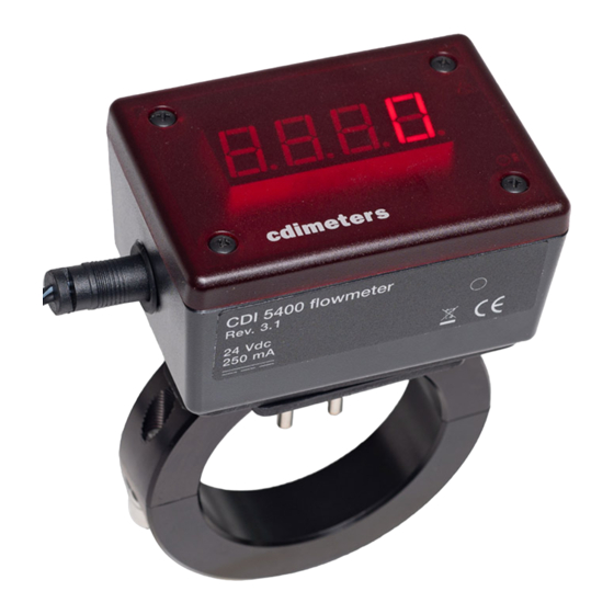
CDI 5400 Flowmeter
Installation and Operating Instructions
Application
The meter may be used with either compressed air or Nitrogen, at pressures
from atmospheric to 200 psig. The air or Nitrogen must be free of oil and
suspended water droplets. In a compressed-air system, the meter should be
downstream of a dryer. Refer to the data sheet for the calibrated range of the
particular meter. The meter will continue to read at much higher flow rates, but
there may be significant inaccuracy
Location
The meter must not be installed in a hazardous location. If it must be installed
where it could be exposed to moisture, consult CDI about weather-resistant
modifications. For best accuracy, the meter should be installed with at least 20
diameters of straight pipe upstream and three diameters downstream. Avoid
Installing The Meter downstream of any item that could distort or concentrate the
flow, such as a partially-closed valve, a regulator, a filter or moisture separator,
two closely-spaced elbows in different planes, a long-radius elbow, an increase
in pipe size or a curved hose. Allow at least 30 diameters of straight pipe
between any such item and the meter. Select a location that meets these
requirements and also provides good visibility from the plant floor.
Preparing the Holes
When the holes are drilled, metal shavings will enter the pipe. Make sure that
filters or other provisions are present downstream to prevent the shavings from
damaging equipment or product or being blown out and causing injury.
Shut down the air and make sure that it will remain shut off while the meter is
being installed. Before starting to drill the holes, make sure that the air pressure
is completely bled down. For the larger size meters, the drill guide is a half ring
with two drill bushings mounted in it. Secure this half ring in place by bolting it to
the back half ring that came with the meter. For the smaller meters, the drill guide
is an aluminum block with two drill bushings. Secure this block to the pipe with a
C clamp, a band clamp or a chain clamp. A universal drill guide, similar to the
small drill guide, is also available that can be used with all meter sizes. After
mounting the drill guide, drill the holes, remove the drill guide, and remove any
burrs that were formed when you drilled the holes.
Advertisement
Table of Contents

Related Manuals for CDI Meters CDI 5400


Summary of Contents for CDI Meters CDI 5400
- Page 1 CDI 5400 Flowmeter Warranty CDI warrants solely to the buyer that the Model 5400 Flowmeter shall be free from defects in materials and workmanship, when given normal, proper and intended Installation and Operating Instructions usage, for three years from the date of purchase. During the warranty period, CDI will repair or replace (at its option) any defective product at no cost to the buyer.
- Page 2 DC- terminal. Power the meter from its wall-plug supply or a 24V dc supply. Note that the DC- terminals are connected to the pipe on which the meter is mounted. © Copyright 2006 - 2010 CDI Meters, Inc. 07.10...
Need help?
Do you have a question about the CDI 5400 and is the answer not in the manual?
Questions and answers