Table of Contents
Advertisement
Quick Links
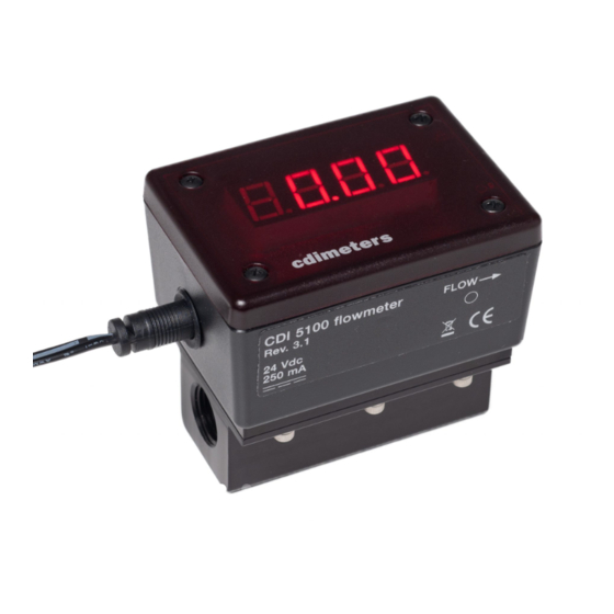
CDI 5100 Flowmeter
Installation and Operating Instructions
Limitations and Cautions
CDI 5100 flowmeters are not for use in hazardous areas or with gasses other
than air or nitrogen or at pressures greater than 250 psig. They are not for use in
control or safety applications. The temperature compensation of the meters is
suitable for use from 20 to 120°F (-7 to 49°C). Best accuracy will be achieved at
temperatures of 40° to 80°F.
Locating the Meter
Each CDI 5100 meter is shipped with a six-inch length of pipe that has been
carefully reamed to provide proper flow into the meter. For best accuracy, this
pipe should be threaded into the inlet of the meter; piping further upstream will
have little effect on accuracy. If you are sealing the joint between the pipe and
the meter with tape, be sure the tape does not intrude on the opening at the end
of the pipe. For accurate and reliable readings in compressed-air applications,
the meter must be installed downstream of a dryer.
If possible, locate and orient the meter for good visibility from the plant floor.
The meters may, when necessary, be installed outdoors. For best visibility, avoid
direct sunlight.
Orienting the Display
The meter must be installed with flow in the direction indicated by the flow arrow.
If doing so will cause the display to be upside-down, remove the cover of the
meter, lift out the display, rotate both 180° and re-install.
Wiring the Meter
Wiring must be in accordance with applicable codes and standards. In areas
where electrical interference may be present, signal wiring should be shielded
with the shield grounded remote from the meter. Signal cables must not be run in
conduit or cable trays shared with power wiring. The main terminal block inside
the meter is accessed by removing the cover and lifting out the display circuit
board.
P
OWER
Either use the dc wall-plug supply furnished with the meter, or connect the
terminals marked "24V dc" to a distributed dc power supply and seal the unused
power opening with the plastic plug provided. The meter will draw a maximum of
250 mA. Unlike earlier 5200 and 5400 meters, the Rev. 3 meters do not connect
the dc- terminal to the pipe on which they are mounted. Please note that 18 Volt
dc supplies furnished with some earlier CDI flowmeters do not provide the
voltage required for Rev. 3 meters.
©
2019 CDI Meters, Inc.
10.19
Advertisement
Table of Contents

Related Manuals for CDI Meters CDI 5100


Summary of Contents for CDI Meters CDI 5100
- Page 1 40° to 80°F. Locating the Meter Each CDI 5100 meter is shipped with a six-inch length of pipe that has been carefully reamed to provide proper flow into the meter. For best accuracy, this pipe should be threaded into the inlet of the meter; piping further upstream will have little effect on accuracy.
- Page 2 “display” to the corresponding terminals in the remote display. The meter may be powered from the remote display if the cable is 22 gauge or heavier and the distance is no greater than 200 feet. CDI 5100 flowmeters require summing remote displays with Rev. 24 or later firmware.
- Page 3 To clean the probes, wipe them with a cloth dampened with alcohol or a similar degreaser. It may be found that the system is clean enough that cleaning is not needed. © 2019 CDI Meters, Inc. 10.19...
- Page 4 CDI be liable to anyone for special, incidental or consequential damages. cdimeters CDI Meters, Inc. support@cdimeters.com 866-885-2462 www.cdimeters.com...
Need help?
Do you have a question about the CDI 5100 and is the answer not in the manual?
Questions and answers