Advertisement
Quick Links
Using the Outputs
The milliamp output is scaled so that four milliamps corresponds to zero flow and
20 milliamps corresponds to the range of the meter indicated on the data sheet.
The meter will display the milliamp full-scale value for a few seconds on startup.
It will also display it if the button on the main (lower) circuit board is pressed
twice.
The pulse output generates a square wave signal, sending one pulse for each
cubic foot of air that passes through the meter. The LED blinks with the pulse
output. At zero flow it may be on or off. The pulse output can be configured as a
threshold output, and the scaling of both the pulse output and the milliamp output
can be changed, using the optional configuration cable.
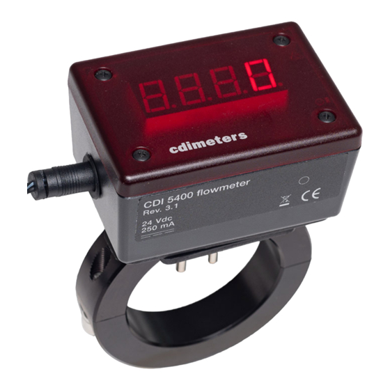
Using the Display
Pressing a button indicated by a circle on the front of the meter cycles the display
through four display options: rate, daily usage, cumulative usage and units of
measure, the last indicated by a digit: (0) for scfm, (1) for m
3
m
/hr. The cumulative values are indicated in thousands of cubic feet or cubic
meters. Holding the button pressed in either of the cumulative modes (daily
usage or cumulative usage) will reset that value to zero. The display normally
defaults to the rate display, but this can be changed, as can the units of measure
and the decimal point location in the cumulative modes. Please refer to
information on configuring the display.
Maintenance
If oil or dirt accumulates on the probes, the meter will read low. For this reason,
we recommend cleaning the probes from time to time. To clean the probes, wipe
them with a cloth dampened with alcohol or a similar degreaser. It may be found
that the system is clean enough that cleaning is not needed.
Warranty
CDI warrants solely to the buyer that the Model 5400 Flowmeter shall be free from
defects in materials and workmanship, when given normal, proper and intended
usage, for three years from the date of purchase. During the warranty period, CDI will
repair or replace (at its option) any defective product at no cost to the buyer. The
foregoing warranty is in lieu of any other warranty, express or implied, written or oral
(including any warranty of merchantability or fitness for a particular purpose). CDI's
liability arising out of the manufacture, sale or supplying of the flowmeter, whether
based on warranty, contract, tort or otherwise, shall not exceed the actual purchase
price paid by the buyer, and in no event shall CDI be liable to anyone for special,
incidental or consequential damages.
cdimeters
CDI Meters, Inc.
support@cdimeters.com
www.cdimeters.com
3
/min and (2) for
866-885-2462
CDI 5400 Flowmeter Rev. 3
Installation and Operating Instructions
Limitations and Cautions
CDI 5400 flowmeters are not for use in hazardous areas or on pipes containing
gasses other than air or Nitrogen. They are not designed for installation under
pressure and they are not for use in control or safety applications. High-pressure
seals are required for all applications above 200 psig (14 barg). Contact CDI
about pressure limitations for applications above 200 psig on Type L or heavier
Copper and Sch. 40 or heavier steel pipe, and for all applications on other types
of pipe. The temperature compensation of the meters is suitable for use from 20
to 120°F (-7 to 49°C). The meters may be applied, at reduced accuracy, at
temperatures up to 150°F (66°C).
Locating the Meter
For accurate and reliable readings, the meters must be installed with adequate
straight pipe upstream, and, in compressed-air applications, they must be
installed downstream of a dryer.
Select a location with a straight run of pipe upstream equal to at least twenty
times the pipe diameter. If the meter is downstream of something that could
distort or concentrate the flow, such as a sweep elbow, a partially-closed valve,
an increase in pipe size or a hose, the run of pipe should be as long as possible;
thirty times the diameter at a minimum. Three diameters of straight downstream
piping is sufficient, unless the meter is immediately upstream of something that
would restrict the flow, such as a valve. If possible, locate and orient the meter
for good visibility from the plant floor.
The meters may, when necessary, be installed outdoors. For best visibility, avoid
direct sunlight.
Preparing the Holes
When the holes are drilled, metal shavings will enter the pipe. Make sure that
filters or other provisions are present downstream to prevent shavings from
damaging equipment or product or being blown out and causing injury.
For the larger size meters, the drill guide is a half ring with two drill bushings
mounted in it. Secure this half ring in place by bolting it to the back half ring that
came with the meter. For the smaller meters, the drill guide is an aluminum block
with two drill bushings. Secure this block to the pipe with a C clamp, a band
clamp or a chain clamp. A universal drill guide, similar to the small drill guide, is
also available; it can be used with all 5400 meter sizes.
Before starting to drill the holes, make sure that the air pressure is completely
bled down. With the drill guide firmly clamped to the pipe, drill the holes, using
©
2014 CDI Meters, Inc.
10.14
Advertisement

Related Manuals for CDI Meters CDI 5400


Summary of Contents for CDI Meters CDI 5400
- Page 1 Limitations and Cautions twice. CDI 5400 flowmeters are not for use in hazardous areas or on pipes containing The pulse output generates a square wave signal, sending one pulse for each gasses other than air or Nitrogen. They are not designed for installation under cubic foot of air that passes through the meter.
- Page 2 The resistance of the loop connected to the output should not exceed 600 Ohms. © © 2014 CDI Meters, Inc. 10.14 2014 CDI Meters, Inc. 10.14...
Need help?
Do you have a question about the CDI 5400 and is the answer not in the manual?
Questions and answers