
Related Manuals for Miller XMT 425 VS


Summary of Contents for Miller XMT 425 VS
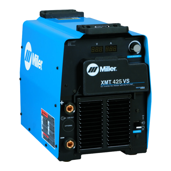
- Page 1 OM-234 202D 2008−12 Processes Multiprocess Welding Description Arc Welding Power Source ™ XMT 425 VS Auto-Line ™ File: MULTIPROCESS Visit our website at www.MillerWelds.com...
- Page 2 We know you don’t have time to do it any other way. That’s why when Niels Miller first started building arc welders in 1929, he made sure his products offered long-lasting value and superior quality.
-
Page 3: Table Of Contents
TABLE OF CONTENTS SECTION 1 − SAFETY PRECAUTIONS - READ BEFORE USING ........1-1. -
Page 5: Section 1 − Safety Precautions - Read Before Using
SECTION 1 − SAFETY PRECAUTIONS - READ BEFORE USING som _2007−04 Protect yourself and others from injury — read and follow these precautions. 1-1. Symbol Usage DANGER! − Indicates a hazardous situation which, if Indicates special instructions. not avoided, will result in death or serious injury. The possible hazards are shown in the adjoining symbols or explained in the text. - Page 6 D Do not use welder to thaw frozen pipes. FUMES AND GASES can be hazardous. D Remove stick electrode from holder or cut off welding wire at contact tip when not in use. Welding produces fumes and gases. Breathing D Wear oil-free protective garments such as leather gloves, heavy these fumes and gases can be hazardous to your shirt, cuffless trousers, high shoes, and a cap.
-
Page 7: Additional Symbols For Installation, Operation, And Maintenance
1-3. Additional Symbols For Installation, Operation, And Maintenance FIRE OR EXPLOSION hazard. MOVING PARTS can cause injury. D Do not install or place unit on, over, or near D Keep away from moving parts such as fans. combustible surfaces. D Keep all doors, panels, covers, and guards D Do not install unit near flammables. -
Page 8: California Proposition 65 Warnings
1-4. California Proposition 65 Warnings For Gasoline Engines: Welding or cutting equipment produces fumes or gases which contain chemicals known to the State of California to Engine exhaust contains chemicals known to the State of cause birth defects and, in some cases, cancer. (California California to cause cancer, birth defects, or other reproduc- Health &... -
Page 9: Section 2 − Consignes De Sécurité − Lire Avant Utilisation
SECTION 2 − CONSIGNES DE SÉCURITÉ − LIRE AVANT UTILISATION fre_som_2007−04 Se protéger et protéger les autres contre le risque de blessure — lire et respecter ces consignes. 2-1. Symboles utilisés DANGER! − Indique une situation dangereuse qui si on Indique des instructions spécifiques. - Page 10 Il reste une TENSION DC NON NÉGLIGEABLE dans LE SOUDAGE peut provoquer un in les sources de soudage onduleur quand on a cendie ou une explosion. coupé l’alimentation. Le soudage effectué sur des conteneurs fermés tel D Arrêter les convertisseurs, débrancher le courant électrique et que des réservoirs, tambours ou des conduites peu décharger les condensateurs d’alimentation selon les instructions provoquer leur éclatement.
-
Page 11: Dangers Supplémentaires En Relation Avec L'installation, Le Fonctionnement Et La Maintenance
D Protéger les bouteilles de gaz comprimé d’une chaleur excessive, ACCUMULATIONS des chocs mécaniques, des dommages physiques, du laitier, des risquent de provoquer des blessures flammes ouvertes, des étincelles et des arcs. ou même la mort. D Placer les bouteilles debout en les fixant dans un support station- D Fermer l’alimentation du gaz protecteur en cas naire ou dans un porte-bouteilles pour les empêcher de tomber ou de non-utilisation. -
Page 12: Proposition Californienne 65 Avertissements
LES FILS DE SOUDAGE peuvent LE RAYONNEMENT HAUTE FRÉ- provoquer des blessures. QUENCE (H.F.) risque de provoquer des interférences. D Ne pas appuyer sur la gâchette avant d’en avoir reçu l’instruction. D Le rayonnement haute fréquence (H.F.) peut D Ne pas diriger le pistolet vers soi, d’autres per- provoquer des interférences avec les équipe- sonnes ou toute pièce mécanique en enga- ments de radio−navigation et de communica-... -
Page 13: Principales Normes De Sécurité
2-5. Principales normes de sécurité Safety in Welding, Cutting, and Allied Processes, ANSI Standard Z49.1, L4W 5NS (téléphone : 800-463-6727 ou à Toronto 416-747-4044, site de Global Engineering Documents (téléphone : 1-877-413-5184, site Internet : www.csa-international.org). Internet : www.global.ihs.com). Safe Practice For Occupational And Educational Eye And Face Protec- tion, ANSI Standard Z87.1, de American National Standards Institute, Recommended Safe Practices for the Preparation for Welding and Cut- 11 West 43rd Street, New York, NY 10036-8002 (téléphone :... -
Page 14: Section 3 − Introduction
SECTION 3 − INTRODUCTION 3-1. Specifications RMS Amps Input at Rated Load Output, Max. 60 Hz 3-Phase at NEMA Load Voltages Amperage Open- and Class I Rating Input Voltage Range in Circuit 208 V 230 V 400 V 460 V 575 V Power Range in CV Mode... -
Page 15: Duty Cycle And Overheating
3-3. Duty Cycle And Overheating Duty Cycle is percentage of 10 min- utes that unit can weld at rated load without overheating. If unit overheats, output stops, a Help message is displayed and cooling fan runs. Wait fifteen min- utes for unit to cool. Reduce amper- age or voltage, or duty cycle before welding. -
Page 16: Section 4 − Installation
SECTION 4 − INSTALLATION 4-1. Dimensions And Weight Hole Layout Dimensions 24 in (610 11-3/4 in (298 mm) 17 in 1-11/16 in (42 mm) (432 mm) 15-3/4 in (400 mm) 19-3/32 in (485 mm) 12-1/2 in 8-11/16 in (221 mm) (318 mm) 1-17/32 in (39 mm) 804 801-A... -
Page 17: Connecting 3-Phase Input Power
4-3. Connecting 3-Phase Input Power Installation must meet all National and Local Codes − have only quali- fied persons make this installation. Disconnect and lockout/tagout in- put power before connecting input conductors from unit. Always connect green or green/ yellow conductor supply grounding terminal first, and never... -
Page 18: Electrical Service Guide
4-4. Electrical Service Guide NOTICE − INCORRECT INPUT POWER can damage this welding power source. Phase to ground voltage shall not exceed +10% of rated input voltage. Actual input voltage should not be 10% less than minimum and/or 10% more than maximum input voltages listed in table. If actual input voltage is outside this range, output may not be be available. -
Page 19: Weld Output Terminals And Selecting Cable Sizes
4-5. Weld Output Terminals And Selecting Cable Sizes* ARC WELDING can cause Electromagnetic Interference. To reduce possible interference, keep weld cables as short as possible, close together, and down low, such as on the floor. Locate welding operation 100 meters from any sensitive electronic equipment. Be sure this welding machine is installed and grounded according to this manual. -
Page 20: Optional Gas Valve Operation And Shielding Gas Connection
‘ 4-6. Optional Gas Valve Operation And Shielding Gas Connection Obtain gas cylinder and chain to running gear, wall, or other station- ary support so cylinder cannot fall and break off valve. Cylinder Regulator/Flowmeter Install so face is vertical. Gas Hose Connection GAS IN Fitting has 5/8-18... -
Page 21: Section 5 − Operation
SECTION 5 − OPERATION 5-1. Front Panel Controls Power Switch ing, place switch in Stick position. For best re- Select setting best suited for application. sults, place Arc Control in the maximum posi- The fan motor is thermostatically Control adjusts inductance when V-Sense tion. -
Page 22: Meter Functions
5-2. Meter Functions The meters display the actual weld output values for approximately three seconds after the arc is broken. Mode Meter Reading At Idle Meter Reading While Welding Scratch 71.7 10.3 Start TIG Actual Volts (OCV) Preset Amps Actual Volts Actual Amps 14.1 10.3... -
Page 23: Lift-Arc Tig Procedure
5-4. Lift-Arc TIG Procedure With Process Switch in the Lift-Arc TIG position, start an arc as follows: TIG Electrode Workpiece Touch tungsten electrode to work- piece at weld start point, hold electrode to workpiece for 1-2 seconds, and slowly lift electrode. An arc will form when electrode is lifted. -
Page 24: Section 6 − Maintenance & Troubleshooting
SECTION 6 − MAINTENANCE & TROUBLESHOOTING 6-1. Routine Maintenance Disconnect power Maintain more often before maintaining. during severe conditions. 3 Months Repair Or Replace Replace Cracked Replace Damaged Or Torch Body Cracked Unreadable Cables Labels Repair Or Replace Cracked Cables And Cords Clean Tighten Weld... -
Page 25: Voltmeter/Ammeter Help Displays
6-3. Voltmeter/Ammeter Help Displays HE.L P−1 HE.L P−5 HE.L P−2 HE.L P−6 HE.L P−3 HE.L P−8 PrO CES heated. The unit has shut down to allow the by the input current. When this limit is All directions are in reference to the front fan to cool it (see Section 3-3). -
Page 26: Section 7 − Electrical Diagram
SECTION 7 − ELECTRICAL DIAGRAM Figure 7-1. Circuit Diagram OM-234 202 Page 22... - Page 27 238 712-A OM-234 202 Page 23...
-
Page 28: Section 8 − Parts List
SECTION 8 − PARTS LIST Ref. 803 729-J Figure 8-1. Parts Assembly OM-234 202 Page 24... - Page 29 Item Dia. Part Mkgs. Description Quantity Figure 8-1. Parts Assembly ....216 034 Wrapper (Includes Insulators and Safety Labels) ....
- Page 30 Item Dia. Part Mkgs. Description Quantity Figure 8-1. Parts Assembly (Continued) ... . . 225 442 Circuit Card Assy, Interconnect W/Label & Clips (Includes) ...
- Page 31 Effective January 1, 2008 (Equipment with a serial number preface of LJ or newer) This limited warranty supersedes all previous Miller warranties and is exclusive with no other Warranty Questions? guarantees or warranties expressed or implied. LIMITED WARRANTY − Subject to the terms and conditions...
-
Page 32: Options And Accessories
Contact the Delivering Carrier to: File a claim for loss or damage during shipment. For assistance in filing or settling claims, contact your distributor and/or equipment manufacturer’s Transportation Department. © PRINTED IN USA 2008 Miller Electric Mfg. Co. 2008−01...
Need help?
Do you have a question about the XMT 425 VS and is the answer not in the manual?
Questions and answers