
Subscribe to Our Youtube Channel
Related Manuals for Hamworthy Stratton mk3


Summary of Contents for Hamworthy Stratton mk3
- Page 1 Stratton mk3 80-150 kW Frame and Header Kits Manual IMPORTANT NOTE THESE INSTRUCTIONS MUST BE READ AND UNDERSTOOD BEFORE INSTALLING, COMMISSIONING, OPERATING OR SERVICING EQUIPMENT UIN 233247 A03...
-
Page 2: Table Of Contents
This kit is suitable for the following boilers: Stratton mk3 80,100,120 & 150 using Natural Gas and 80,100 & 120 using Propane CONTENTS 1 Introduction ..............3 2 General Description of Systems ........3 3 Multiple Boiler System Components ......6 4 Frame Kit Installation Procedure ........9 5 Header Kit Assembly ............10... -
Page 3: Introduction
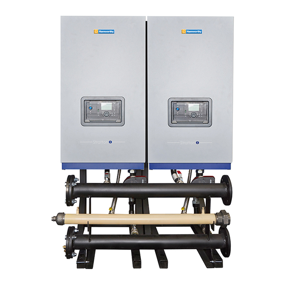
2.1 FRAME AND HEADER KIT DESIGN OPTIONS The Stratton mk3 boilers are suitable for use in a multiple boiler configuration. The Stratton mk3 multiple boiler system is available in side by side and giving the opportunity to choose the optimum footprint size or wall space for a given output. 80-150 kW kits include the support frame. - Page 4 System separation PHEX kits are offered at the below kW ratings and are supplied with suitable pipe spools for connection to frame and header kits. Table 5 System Seperation PHEX Kits Product Number Frame and Header Size PHEX kW 232893 DN80 232894 DN80...
- Page 5 2.5 GAS SUPPLY For Stratton mk3 the 80, 100, 120 & 150 boilers are configured for use with natural gas, or 80,100 & 120 running on Propane. Connection to the gas supply must be in accordance to with all the applicable regulations.
-
Page 6: Multiple Boiler System Components
MULTIPLE BOILER SYSTEM COMPONENTS 3.1 GENERAL The multiple boiler systems consist of the following components: • Pipekit (1 and 2 wide configurations) • Boiler gas header. • Boiler flow and return headers supported on mounting skid • Low loss mixing header (optional) •... - Page 7 3.5 BOILER CONNECTION KITS The connection kit contains the following components: 1. Boiler return leg complete with isolating valve, pump, non return valve, drain cock and fibre seals. 2. Boiler flow leg complete with isolating valve, pressure relief valve and fibre seals. 3.
- Page 8 IMPORTANT POINTS Before commencing installation: • The frames must stand on a flat and level floor of suitable load bearing capacity. • The header must be bolted to the frame before the hoses are connected to the boiler. MOUNTING FRAME MUST BE SECURED TO THE FLOOR WITH BOLTS Allowances must be made for installation where features are in place that may affect the nominal installation conditions.
-
Page 9: Frame Kit Installation Procedure
FRAME KIT INSTALLATION PROCEDURE 4.1 SIDE BY SIDE FRAME KIT MOUNTING PROCEDURE 1. Place the frame kit sections in the required position and bolt them together at the top and bottom with the bolts, nuts and washers provided. IMPORTANT: MOUNTING FRAME MUST BE SECURED TO THE FLOOR WITH BOLTS 2. -
Page 10: Header Kit Assembly
4.2 BOILER MOUNTING 1. As appropriate mount the boilers onto either the wall plates or the side by side pipekit. LOW LOSS HEADER ASSEMBLY (OPTIONAL ACCESSORY) FITTING LOW LOSS HEADER AND BLANKING FLANGES 1. Fit the low loss header and blanking flanges in the chosen positions. Note. - Page 11 5.2 FITTING HEADER KIT ASSEMBLY ( Steps 1 thru 5 are applicable to Magna 1 and UPMXXL 1. Slide the header kit assembly between the frame legs but do not screw the header kit to the frame at this stage. 2.
- Page 12 UPMXXL INSTRUCTIONS 6. Fit the pump to the boiler return connection using the gaskets provided. 7. Fit the two flexible header connections to the boiler pump connection and the flow connection using the sealing washers provided. 8. Tighten header feet to frame feet bolts. UPMXXL shown 5.3 FITTING GAS CONNECTION 1.
-
Page 13: Installation Drawings For Multiple Boiler Systems
5.6 ASSEMBLE HEADER ONTO FRAME 1. Tighten the header bolts onto the frame. 2. Ensure that the test points on the gas header are accessible. Note: The test point nearest the inlet to the rigs is deemed as the appliance pressure test point for the appliances fitted). - Page 14 6.2 SIDE BY SIDE FRAME KIT CONFIGURATION 6.2.1 INSTALLATION DRAWING WITH 1 - DN80 120 kW BOILER (OPTIONAL LOW LOSS HEADER SHOWN FOR INFORMATION) NOTE: LOW LOSS HEADER OR PLATE HEAT EXCHANGER AND GAS NOTE: LOW LOSS HEADER OR PLATE HEAT EXCHANGER AND GAS CONNECTIONS CAN BE LOCATED EITHER ON THE LH OR RH SIDE OF CONNECTIONS CAN BE LOCATED EITHER ON THE LH OR RH SIDE OF THE ASSEMBLY TO SUIT THE REQUIREMENT OF THE INSTALLATION...
- Page 15 6.2.3 INSTALLATION DRAWING WITH 2 - DN80 80-120 kW BOILERS (SIDE BY SIDE) (OPTIONAL LOW LOSS HEADER SHOWN FOR INFORMATION) All dimensions in mm 6.2.4 INSTALLATION DRAWING WITH 2 - DN100 150 kW BOILERS (SIDE BY SIDE) (OPTIONAL LOW LOSS HEADER SHOWN FOR INFORMATION) NOTE: 1.
- Page 16 6.2.5 INSTALLATION DRAWING WITH 3 – DN80 80-120 kW BOILERS (SIDE BY SIDE) (OPTIONAL LOW LOSS HEADER SHOWN FOR INFORMATION) All dimensions in mm 6.2.6 INSTALLATION DRAWING WITH 3 – DN100 150 kW BOILERS (SIDE BY SIDE) (OPTIONAL LOW LOSS HEADER SHOWN FOR INFORMATION) NOTE: 1.
- Page 17 6.2.7 INSTALLATION DRAWING WITH 4 – DN80 80-120 kW BOILERS (SIDE BY SIDE) (OPTIONAL LOW LOSS HEADER SHOWN FOR INFORMATION) All dimensions in mm 6.2.8 INSTALLATION DRAWING WITH 4 – DN100 150 kW BOILERS (SIDE BY SIDE) (OPTIONAL LOW LOSS HEADER SHOWN FOR INFORMATION) NOTE: 1.
- Page 18 6.2.9 INSTALLATION DRAWING WITH 5 – DN80 80-120 kW BOILERS (SIDE BY SIDE) (OPTIONAL LOW LOSS HEADER SHOWN FOR INFORMATION) All dimensions in mm 6.2.10 INSTALLATION DRAWING WITH 5 – DN100 150 kW BOILERS (SIDE BY SIDE) (OPTIONAL LOW LOSS HEADER SHOWN FOR INFORMATION) NOTE: 1.
- Page 19 6.2.11 INSTALLATION DRAWING WITH 6 - DN80 80-100 kW BOILERS (SIDE BY SIDE) (OPTIONAL LOW LOSS HEADER SHOWN FOR INFORMATION) All dimensions in mm 6.2.12 INSTALLATION DRAWING WITH 6 – DN100 150 kW BOILERS (SIDE BY SIDE) (OPTIONAL LOW LOSS HEADER SHOWN FOR INFORMATION) NOTE: 1.
-
Page 20: Electrical Connections & Wiring Diagram
ELECTRICAL CONNECTIONS & WIRING DIAGRAM 7.1 INSTALLER CONNECTIONS FOR MAGNA 1 BOILER PUMP Note. Used with DN100 frame and header kits. 80-150 kW Frame & Header Kits Manual... - Page 21 7.2 INSTALLER CONNECTIONS FOR UPMXXL BOILER PUMP Note. Used on DN80 frame and header kits using low loss headers or plate heat exchangers. 80-150 kW Frame & Header Kits Manual...
-
Page 22: Commissioning And Testing
COMMISSIONING AND TESTING 1. Electrical and gas safety checks must be carried out on completion of installation as with individual boiler commissioning. 2. Pump setting - follow the instructions supplied with the pump, referring to the installation manual FIRST THIS DRAWING REFERENCES A 3D FILE OF THE SAME THIS DOCUMENT IS COPYRIGHT PROTECTED BY IDEAL BOILERS. - Page 23 NOTES 80-150 kW Frame & Header Kits Manual...
- Page 24 Poole, Dorset, BH17 0NF Telephone: 01202 662500 Fax: 01202 662522 Email: service@hamworthy-heating.com Website: www.hamworthy-heating.com 80-150 kW Frame & Header Kits Manual Hamworthy reserves the right to make changes and improvements which may necessitate alteration to the specification without prior notice.
Need help?
Do you have a question about the Stratton mk3 and is the answer not in the manual?
Questions and answers