Advertisement
Advertisement

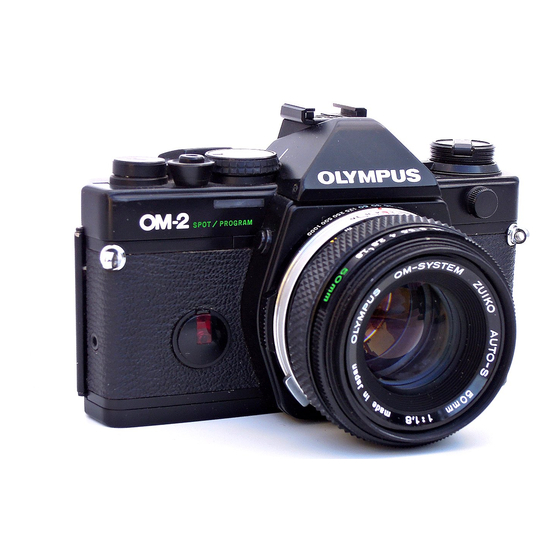
Related Manuals for Olympus 2


Summary of Contents for Olympus 2
-
Page 2: To An Om-2 Owner
In addition, it offers full manual exposure control at the flip of a lever switch. OM-2 has set a new standard for relia- bility and versatility in a compact SLR, to meet the demands of the professional and amateur alike, for standard as well as scientific and technical photography pursuits. -
Page 3: Description Of Controls
(P.58) Viewfinder Eyepiece Frame Battery ( P . 8 ) Check Lamp Rewind Shaft Film Chamber Film Guide Pins (2) (P. 43) Shutter Curtain Motor (P. 37, P. 40) Guide Pin Hole Battery (P. 7) Chamber Motor Drive Socket Cap Tripod Socket (P. -
Page 4: P.20, P.
Manual Shutter Speed Ring Lens Release Button FP and X Flash Synch Selector Flash Synchronization Socket Rewind Knob /Camera Back Release Rewind Crank (P.9, P.20, P. 44) Selector Lever Hot Shoe Socket (P. 12) (P. 7) (P.30, P.35) (P.35) (P.20) (P. -
Page 5: Accessory Shoe
Accessory Shoe 4 Rewind Release Lever Shoulder Strap Eyelet (P.20, P.44) Self-Timer (P.21, P.44) (P. 25, P. 26.) Depth-of-Field Lens Preview Button... -
Page 6: Table Of Contents
TABLE OF CONTENTS On OM-2 To an OM-2 Owner ....1 Description of Controls ... . 2 Mounting the Lens/Inserting the Batteries . - Page 7 Motor Drive Photography ... 37 Winder 2 Operation ....40 Care and Storage ....42 Questions and Answers .
-
Page 8: Mounting The Lens/Inserting The Batteries
MOUNTING THE LENS Mount the Lens. Align the red dots on the lens flange and the body mount ring. Turn the lens clockwise until the lens release button springs up and you will hear posi- tive "click". Lens Removal To detach the lens, press down on the lens release button and turn the lens counter-clockwise. -
Page 9: Battery Check And Mirror Lock-Up
BATTERY CHECK AND MIRROR LOCK-UP By pressing the selector lever to the "CHECK• RESET" position, you can check the batteries and/or unlock the mirror. Check the Batteries. Move the selector lever to the "CHECK•RESET" position. The battery check lamp indicates bat- tery condition as follows: The red lamp lights brightly —... -
Page 10: Loading The Film
LOADING THE FILM Pull the rewind knob up and open the camera back. Insert a film cartridge into the film chamber and push the rewind knob back. Insert the film leader into one of the slots in the film take-up spool. Turn the advance lever so that the film perfora- tions engage the sprocket teeth. -
Page 11: Operating The Film Advance Lever/Exposure Counter
EXPOSURE COUNTER Exposure Counter The exposure counter is indexed from "S" (Start) to 1, 2 ... up to 36 in even numbers and "E" (End). Whenever the camera back is opened, the exposure counter automatically returns to "S". -
Page 12: Setting The Asa Film Speed Dial
SETTING THE ASA FILM SPEED DIAL Lift up the outer collar of the exposure com- pensation dial and rotate until the ASA speed for the film appears in the window. The ASA film speed scale on the dial is mark- ed from 12 to 1600. -
Page 13: Aperture Ring And Manual Shutter Speed Ring
The other engravings indicate fractions of a second; for ex- ample "T" for 1 second, "2" for 1/2 second ... up to "1000" for 1 /1000 second. To set at "B", rotate the ring while pressing the B LOCK but- ton at the lower left of the body mount. -
Page 14: Setting The Selector Lever/Viewfinder
1) AUTO — Automatic exposure control; you preset the F stop and the camera automatical- ly sets shutter speed for proper exposure. 2) OFF — Camera turned completely off to avoid battery drain. Always store your camera with the selector lever in this position. -
Page 15: Focusing
FOCUSING In focus. Look through the viewfinder and turn the focusing ring in either direction until your subject appears sharpest. The split image will be vertically aligned in the central spot of the Focusing Screen or a shimmering effect of the microprism ring around the central spot will disappear when critical focus- ing has been achieved. -
Page 16: Automatic Exposure Control
AUTOMATIC EXPOSURE CONTROL The Aperture-Preferred System The aperture-preferred system is the most convenient and easy-to-use method of auto- matic operation, particularly outdoors when using 50mm or wide-angle lenses. To use this system: Set the selector lever to the "AUTO" position making sure that the lever "clicks"... - Page 17 1/1000 second. Since this is beyond the range of your OM-2 and an overexposed photo- graph would result, turn the lens aperture ring to a higher F stop until the meter needle moves out of the red zone.
-
Page 18: Manual Exposure Control
MANUAL EXPOSURE CONTROL Set the selector lever to "MANUAL", and the ex- posure index marks and the meter needle are visi- ble in the viewfinder. Shutter Speed-Preferred Manual Exposure Control Should you wish to preselect a shutter speed turn the shutter speed ring until the desired speed is opposite the red reference dot on the lens barrel (see page 12). - Page 19 Light Measuring Range of the Exposure Meter The measuring range is EV 1.5-EV17 (ASA 100, with F1.2 55mm lens). The list above summarizes the lowest measurable limits in dealing with ex- treme low light conditions. CAUTION: If the aperture ring or shutter speed...
-
Page 20: Holding The Camera
HOLDING THE CAMERA Proper camera handling is important in assuring the sharpest possible pictures. Holding the Camera Horizontally Keep both elbows close to the body, to steady the camera. Putting the Camera into Operation The aperture ring, focusing ring and shutter speed ring are so arranged as to enable one hand opera- tion right up to the moment the shutter is released. -
Page 21: Unloading The Camera/Making Multiple Exposures
UNLOADING THE CAMERA When the entire roll of film has been exposed re- wind the film. Turn the rewind release lever counter-clock- wise by about 90°. Fold out the rewind crank and wind it in the direction of the arrow. While rewinding, you will feel tension on the crank. -
Page 22: Setting The Self-Timer
SETTING THE SELF-TIMER Rotate the self-timer lever counter-clockwise so that the shutter can be released after an elapse of delay time between 4 sec. to 12 sec. according to the lever setting as shown above. You may set the self-timer lever either before or after advancing the film. -
Page 23: Exposure Compensation
EXPOSURE COMPENSATION After compensation Before compen- sation When the most im- portant area of the picture is much darker than the general picture area (blue sky, snowfield, etc.), the meter will have a tendency to read the brightest part of the picture leaving the main sub- ject under-exposed. -
Page 24: Exposure Compensation For Automatic Measurement
EXPOSURE COMPENSATION FOR AUTOMATIC MEASUREMENT If you wish to change the exposure setting auto- matically selected by the camera, use the exposure compensation dial and a compensation marker appears in the viewfinder. When the main subject is much darker than the general background or when strong light strikes the subject from behind or from the side, turn the dial to the (+) side. -
Page 25: Exposure Compensation For Manual Measurement
EXPOSURE COMPENSATION FOR MANUAL MEASUREMENT 1 Stop Over 1/2 Stop Over Manual exposure can be compensated by adjust- ing the F stop or shutter speed. The exposure needle indicates over-exposure at the (+) side, or under-exposure at the (—) side. -
Page 26: Depth Of Field
DEPTH OF FIELD F16, 1/15 sec. F2, 1/1000 sec. Depth of field is the area of acceptable sharpness in front of and behind the subject in focus. As you get closer to your subject or as you open your lens (e.g. from F16 to F2.8) the depth of field becomes shallower. -
Page 27: Depth Of Field Scale/Preview Button
DEPTH OF FIELD SCALE The double series of numbers engraved on the depth of field scale represents F stops: F4, F8, and F16. Once you have focused on your subject, all objects within the distance range indicated on the lens distance scale between the marks for the F stop you have selected will have acceptable sharpness. -
Page 28: Infrared Photography/Camera Back Replacement
CAMERA BACK REPLACEMENT The camera back of the OM-2 is fully interchanbe- able with the Recordata Back 2, 3 and 250 Film Back 1. To remove the camera back, push down on the release pin as shown. Do not remove the back unless necessary. -
Page 29: Interchangeable Focusing Screens
INTERCHANGEABLE FOCUSING SCREENS The OM System interchangeable focusing screens provide you with the ultimate in focusing versa- tility. Optional screens are available to suit virtual- ly every picture-taking situation. The focusing screens come with a special tool. To remove the focusing screen: a) Detach the camera lens from the camera body. -
Page 30: Flash Photography With The T32 (T20) Electronic Flash
The T32 and T20 are the world's first fully auto- matic electronic flash units. All their functions are controlled directly by the OM-2 to perform ex- tremely easy, yet highly accurate flash exposures. (See pp. 61~69 for further information on flash... - Page 31 Attach the Acces- sory Shoe 4 to the OM-2 and mount the T32 (or T20). Set the camera's se- lector lever to the "AUTO" position and switch on the T32 (or T20). NOTE: Mounting the T32 (or T20) on the acces- sory shoe automatically completes the "X"...
- Page 32 In case exposure must be achieved by flash illumi- nation, turn the aperture ring until the meter needle points to 1/30 sec. or slower, and shoot. NOTE: The OM-2 incorporates an incorrect flash prevention system. If the shutter speed is faster than the flash synchronizing range, the electronic flash will not fire when you press the shutter re- lease button.
-
Page 33: The T32(T20)/Om-2 Way-Flash Photography Couldn't Be Simpler And More Accurate
Picture angle = Light measuring All required of the T32 (T20) is a flick of the on/ off switch. The rest is taken care by the OM-2. The dial settings required of conventional "auto" flash units — ASA film speed setting, aperture setting, flash mode switching, exposure compensation —... -
Page 34: Bounce Flash
BOUNCE FLASH The T32 flash surface can be tilted upward through an angle of 90°, providing easy bounce TTL Auto flash. Point the flash surface at the ceiling so that the subject is illuminated by soft reflected light. -
Page 35: Cloce-Up Flash
CLOSE-UP FLASH Close-up in TTL Auto flash can be achieved sim- ply by tilting the flash surface downward (up to 15°). -
Page 36: Flash Photography With An Electronic Flash Unit
FLASH PHOTOGRAPHY WITH AN ELECTRONIC FLASH UNIT OTHER THAN THE T32-T20 Attach the Accessory Shoe 4 to the OM-2. Mount the electronic flash on the accessory shoe. If your electronic flash unit does not have a direct contact "hot shoe", connect its syn- chronizing cable to the camera flash socket. -
Page 37: Flashbulb Photography
FLASHBULB PHOTOGRAPHY Plug the synchronizing cable leading from the flash unit into the camera flash socket, and then attach the flash unit to the camera. Select the proper synchro setting from the table below according to the type of bulb be- ing used, and align the red dot on the X and FP flash selector with the "X"... -
Page 38: Motor Drive Photography
MOTOR DRIVE PHOTOGRAPHY Motor Drive 1 The standard motor drive unit forms the heart of the Motor Drive Group. An extremely high-per- formance unit capable of high-speed sequence shooting at 5 frames per second, operating off various power units. Can be switched to the "single"... - Page 39 Attaching the Motor Drive 1 Remove the motor drive socket cap from the camera base plate. Insert the motor drive guide pin into the guide pin hole on the camera base plate. Turn the clamping screw clockwise until the Motor Drive 1 is securely attached to the camera base plate.
- Page 40 MOTOR DRIVE PHOTOGRAPHY Photography with the Motor Drive Units Using the M. 18V Control Grip 1 Unlock the shutter release lock lever on the Control Grip. Turn the mode selector on the Control Grip to either "SINGLE" or "SEQUENCE". Set the mode selector to the "OFF"...
-
Page 41: Winder 2 Operation
WINDER 2 OPERATION Winder 2 The unit provides the OM cameras with automatic film winding capability for single-frame as well as sequential filming (max. 2.5 frames per second). Shutter Release Remote Control Jack Non-Slip Finger Grip Guide Pin Mode Selector... - Page 42 Insert the guide pin into the guide pin hole on the camera base plate. Turn the clamping screw clockwise until the Winder 2 is securely attached to the cam- era base plate. Taking the pictures Pull up and rotate the mode selector to the "SINGLE"...
-
Page 43: Care And Storage
CARE AND STORAGE General Dust and moisture are harmful agents affecting your camera. Remove the camera from the case and store it in a dry, well-ventilated place mak- ing sure the shutter and self-timer are free from tension. Do not store the camera near moth balls or similar volatile chemical materials to avoid the possibility of damage to metal surfaces. - Page 44 Have all repairs performed by an authorized OLYMPUS Service Center. You may send it through the store where you bought your cam- era or directly to an Olympus Service Center. Parts Do not press the shutter release button at random.
-
Page 45: Questions And Answers
The rewind release lever may not be rotated in the arrow direction until it aligns with the "OM-2" marking. (See page 20.) Why can't I set the ASA film speed I need? At the most, 3 stops can be advanced in a single stroke of the dial. - Page 46 Can film be properly exposed when the selec- tor lever is in the "OFF" position? The OM-2 is designed to always expose the film 1/30 second or faster (ASA 100) with the selector lever at the OFF position. If the shutter is unintentionally released in darker condition on "OFF"...
- Page 47 (See page 28.) If this does not solve the pro- blem, send your camera to an authorized OLYMPUS Service Center. Is it normal for the microprism in the center of the viewfinder to "shimmer" and darken? Yes, when a lens with a maximum aperture smaller than F5.6 is mounted on the camera.
-
Page 48: The Most Important Feature Of The
THE MOST IMPORTANT FEATURE OF THE OM-2-TTL DIRECT(OTF)LIGHT Diagram of light path in conventional SLRs Before shutter release The instant the shutter has been released (A memory device controls the shutter speed, based on the light reading taken before actual exposure.) - Page 49 2. The sensors measure flash intensity as it builds up and cut off its light at the source when the correct exposure level is reached. (TTL Cen- tralized Control Flash) 3.
- Page 51 • Tough and reliable shutter, viewfinder, etc. When these exacting conditions have been satis- fied, an OM-2 is born as a true system camera that controls an entire SLR comprehensive system. The OM-2 is backed up with over 300 components systematically organized under eight groups —...
-
Page 52: Zuiko Interchangeable Lens Group
49mm filters for most lenses from 21mm to 200mm. As part of the OM System design all the lenses now offer higher perform- ance in small configurations. Olympus has pro- duced lenses for microscopes for decades and the new Zuiko lenses benefit from this scientific experience. -
Page 54: Table Of Interchangeable Lenses
230g ( 8 . 1 ) ( 3 . 3 ) 1.5 m 32×21cm ( 4 . 9 ) 3 6 0 g ( 1 2 . 7 ) 1.5 m (4.9) 32×21cm 2 9 0 g ( 1 0 . 2 ) (6.0) - Page 55 In the combination marked with *, micro- prism, split-prism edges finder will darken. Compatible: meter in the OM-1 and OM-2 (on MANUAL) cannot used. AUTO, the OM-2 makes correct exposures, but the meter needle does indicate correct shutter speeds. (Specifications subject...
-
Page 56: Interchangeable Lens Group Units
INTERCHANGEABLE LENS GROUP UNITS Lens Hoods Lens hoods protect against ex- traneous light striking the lens causing unwanted glare. Hoods for standard lenses are cover types and can be reversed provide easy storage even when the camera is in the case. Five lens hoods are optionally available (see TABLE OF IN- TERCHANGEABLE... - Page 57 L39 (UV) Colorless May be used at all times to protect the lens. B. & W. Reduces the quantity of light entering the lens to 1/2 Grey or 1/4 of the original intensity. For use in extremely Color bright conditions when you wish to maintain a wide Grey aperture.
-
Page 58: Finder Group
SLR cannot be expected to fulfill its essential func- tion without the provision for changing of focus- ing screens. The OM-2 is provided with a view- finder that offers a far brighter, large image than previous 35mm SLR cameras. The Finder Group... -
Page 59: Finder Group Units
360°, for use in low level and 90° angled shots. The two-stage, one-touch switching system offers both a 1.2x magnification image cover- ing the whole screen, and a 2.5x enlargement of the central por- tion for critical focusing. For photomicrographic use,... - Page 60 FINDER GROUP UNITS TYPE SCREEN Microprism-matte type (for most lenses) Microprism-matte type (for standard & telephoto lenses) Split image-mane type (for most lenses) All matte type (for most lenses) Microprism -clear field type (for wide angle & standard lenses) Microprism-clear field type (for standard &...
- Page 61 Bellows and extension tubes. For focusing in low magnification close- up photography, use the matte area and in macrophotography greater than life size, use the double cross hairs the same way as with the 1 -1 2. The meter needle indicates proper exposures, but depending on the conditions of the specimen, the reading must be compensated for.
-
Page 62: Flashphoto Group
35mm wide angle lens. The T32 (or T20), when used with the OM-2, is an OTF (off-the-film) ful- ly automatic electronic flash unit. Even the dial settings (auto/manual switching, aperture setting and ASA film speed setting) required of conven- tional "auto"... - Page 64 FLASH PHOTOGRAPHY SYSTEM CHART CLIP-ON BOUNCE FLASH MULTI- REMOTE CONTROL MOTOR DRIVE UNIT FLASH FLASH FLASH...
-
Page 65: Flashphoto Group Units
1.5V C (inside bounce grip) including Ni-Cd, or AC house current. 77 x 68 x 57mm (3" x 2.7" x 2.2"), 160g. (5.6 oz.) less batteries. T10 Ring Flash 1 Designed principally for use with the OM System macro lenses, this... -
Page 66: Flash Photo Group Units
FLASH PHOTO GROUP UNITS TTL Centralized Control Flash by T32 (T20)/ OM-2 Combination The T32 (T20) utilizes the OM-2's own built-in SBC light sensors. The sensors read the build-up of light from the T32 (T20) which passes through the taking lens to reach the film surface, letting... - Page 67 TTL Auto Cords for simultaneous flash photography. TTL Auto Connector T20 Allows the T20 to perform off- camera flash via the TTL Auto Cord T when the Power Bounce Grip 2 is not used (i.e., hand-held or tripod mounted).
- Page 68 5m cords are available. M. Grip Cord Connects the remote shutter re- lease on the Power Bounce Grip 2 for operation with the Motor Drive 1 or Winder 2 units. Power Bounce Grip 2 An auxiliary power unit which...
- Page 69 Enables operation of the T10 Ring Flash 1 and its modelling lamp on AC current. Electronic Flash AC Adapter 2 Plugged into an AC wall outlet, this unit supplies a virtually un- limited number of economical flashes with the T32 (or T20).
- Page 70 Quick on four AA batteries (2~ 3 sec.). PS200: 31 x 55 x 64mm (1.2" x 2.2" x 2.5"), 75g. (2.6 oz.) less batteries. PS200 Quick: 32 x 73 x 71mm (1.3" x 2.9" x 2,8"), 95g. (3.4 oz.) less bat- teries.
-
Page 72: Motor Drive Group
300mm telephoto lens, for shooting sports and news events or other action subjects. The Winder 2 is designed for the ultimate compactness operating on self-contained batteries to perform single or sequential shooting. - Page 74 CHART OF MOTOR DRIVE GROUP...
-
Page 75: Motor Drive Group Units
3.23 2.59 in.). Weight: 210g (7.4 oz.). Winder 2 via a 1.2m cord. Warm- ed by photographer's body heat, permits operation in tempera- tures as low as—10° C (14° F). M.18V Control Grip 1 (with M. 18V Battery Holder 1) A power supply that accepts 12 AA batteries. - Page 76 M. 15V Ni-Cd Control Pack 1. 250 Film Back 1;250 Film Magazine Used with the Motor Drive 1 or Winder 2 for roll films up to 250 exposures. Two Magazines are necessary. Relay Cords 1.2m and 10m Extension...
-
Page 77: Macrophotography Group
MACROPHOTOGRAPHY GROUP Due to recent advances in macrophotography, it has become possible to discover patterns and colors of unsuspected beauty in the minutiae of nature. A fast growing number of scientists and amateurs are taking the opportunity to explore the living world around them to new depths. The Macrophotography Group of the OM System provides all the tools necessary to capture this world of perfection on film, offering a complete... - Page 78 CHART OF MACROPHOTOGRAPHY GROUP...
-
Page 79: Macrophotography Group Units
Subject area extends to 72mm x 48mm (2.8" x 1.9") when used in conjunc- tion with the 135mm macro lens, and runs all the way from 72mm x 48mm (2.8" x 1.9") to 36mm x 24mm (1.4"... - Page 80 Auto Bellows basic unit extending your close-up and macrophotographic capabilities. Provided with the preset aperture diaphragm lever to stop down the lens opening of various OM lenses at the mo- ment of exposure in conjunc- tion with the double cable re- lease.
- Page 81 Ring Flash 1 and its modelling lamp on AC current. 6V Power Pack 2 An auxiliary power source unit for the modelling lamp of the T10 Ring Flash or winder units. Powered by four D size batteries. Electronic Flash AC Adapter 2...
- Page 82 Macrophoto Stand Extension Bar VST-E Extends the height of the Macro- photo Stand. Length: 7.5cm (2.95"). Trans-llluminator Base X-DE Indispensable holding the Macrophoto Stand VST-1 magnified photographs. Suppli- ed with a built-in 100V 20W illuminator with a mirror, and a pair of wooden handrests for ease of operation.
- Page 83 Epi-llluminators PM-LSD 2 This pair of illuminators offers vertical illumination essential to macrophotography. The height of the illuminator is adjustable on the tall pillar, suitable to over- stage or substage illumination. When used with the Trans-illumi- nator Base X-DE, the Illuminator supplies transmitted light.
- Page 84 MACROPHOTOGRAPHY GROUP UNITS Incident Illuminator Mirror Housings PM-EL80, PM- EL38and PM-EL20 These units used with OLYMPUS Macro Lenses in con- junction with the Epi-lllumina- PM-LSD2 Macrophoto- graphic Equipment PMT-35 to illuminate macrophotographic objects with incident light. They are effective when shadowless pictures are desired.
-
Page 85: Phototechnical Group
OM body. Other outstanding advantages of this group are the Recordata Backs 3 and 2 that are interchange- able with the OM standard camera back. Once in place, the No. 3 Back automatically records the... - Page 88 CHART OF PHOTOTECHNICAL GROUP...
-
Page 89: Phototechnical Group Units
Data display on the liquid crystal panel. Recordata Back 2 The Back fits on the OM body and imprints data in the lower right corner of the picture. The... -
Page 90: Photomicrography Group
The exciting vision of look- ing at the microscopic world through a microscope can be recorded by the OM-2. OLYMPUS has an outstanding reputation for manufacturing precision microscopes used by scientists throughout the world. - Page 92 CHART OF PHOTOMICROGRAPHY GROUP...
-
Page 93: Photomicrography Group Units
PM-ADP, PM-ADF Used to connect a microscope to OM-Mount Photomicro Adapter L. Each Adapter desig- nates OLYMPUS microscope eyepieces, as follows; PM-ADG- 3 for G eyepieces, PM-ADP for P eyepieces and PM-ADF for FK photo eyepieces. Light Shield Tube PM-SDM... - Page 94 PHOTOMICROGRAPHY GROUP UNITS System PM-10-AD Consists of 17 units, including PM-PBS, PM-CBAD, etc. Automatic Exposure Body PM-PBS Automatically determines curate exposure time. Automatic Exposure Control Box PM-CBAD Used with the Automatic Expo- sure Body PM-PBS, to regulate color temperatures control, re- ciprocity failure, etc.
-
Page 95: Chart Of Photographic Ranges
CHART OF PHOTOGRAPHIC RANGES GROUPS ZUIKO INTERCHANGEABLE LENS GROUP MACROPHOTOGRAPHY GROUP PHOTOMICROGRAPHY GROUP MACROPHOTOGRAPHY GROUP... -
Page 96: Case Group And Units
CASE GROUP UNITS Hard Case for OM Body with F1.8 or F1.4 Hard Case for OM Body with F1.2 Accommodates the OM Body with respective standard lens. Semi-Hard Case for OM Body with F1.8 or F1.4 Semi-Hard Case for OM Body with F1.2... - Page 97 Compartment Case S A hard shoulder case with two adjustable partitions. Holds OM Body with two interchangeable lenses and filters, or with Elec- tronic Flash T32 and Bounce Grip. Camera Holder for Case M Besides the camera holder pro- vided with the Case M, more camera holder is attacha- ble on the right or left wall of...
- Page 98 CHART OF CASE GROUP Compartment Case S Compartment Case M Compartment Case L Motor Drive Partitioned Insert...
-
Page 99: Main Specifications
Manual exposure: TTL type. Measuring system: Full aperture center-weighted metering. Meas- uring range: EV1.5-EV17 (ASA 100 with F1.2 standard lens). Light sensors: 2 CdS sen- sors. Zero-method with needle visible in viewfinder. Film speed setting: ASA 12—1600, set by lifting and rotating film speed dial. - Page 100 (5.35" x 3.27" x 3.19") 690g (24.3 oz) With F1.4 lens: 136 x 83 x 89mm (5.35" x 3.27" x 3.50") 750g (26.5 oz) With F1.2 lens: 136 x 83 x 97mm (5.35" x 3.27" x 3.82") 830g (29.3 oz)
- Page 101 OLYMPUS OPTICAL CO.,LTD. San-Ei Building, 22-2, Nishi Shinjuku 1-chome, Shinjuku-ku Tokyo, Japan. T e l . 03-340-2211 OLYMPUS CORPORATION Crossways Park, Woodbury, New York 11797, U.S.A. Tel. 5 1 6 - 3 6 4 - 3 0 0 0 OLYMPUS OPTICAL CO.(EUROPA) GMBH 2 Hamburg 1, Steindamm 105, West Germany.
Need help?
Do you have a question about the 2 and is the answer not in the manual?
Questions and answers