Table of Contents
Advertisement
Quick Links
Tel: +49 40 528 401 0
Fax: +49 40 528 401 99
Web:
www.visionsystems.de
Support:
service@visionsystems.de
User Manual
User Manual
User Manual
User Manual
User Manual
User Manual
User Manual
User Manual
User Manual
User Manual
User Manual
User Manual
User Manual
User Manual
User Manual
User Manual
User Manual
User Manual
User Manual
User Manual
User Manual
User Manual
User Manual
User Manual
User Manual
User Manual
User Manual
User Manual
User Manual
User Manual
User Manual
User Manual
User Manual
ModGate Plus
ModGate Plus
ModGate Plus
ModGate Plus
ModGate Plus
ModGate Plus
ModGate Plus
ModGate Plus
ModGate Plus
ModGate Plus
ModGate Plus
ModGate Plus
ModGate Plus
ModGate Plus
ModGate Plus
ModGate Plus
ModGate Plus
ModGate Plus
ModGate Plus
ModGate Plus
ModGate Plus
ModGate Plus
ModGate Plus
ModGate Plus
ModGate Plus
ModGate Plus
ModGate Plus
ModGate Plus
ModGate Plus
ModGate Plus
ModGate Plus
ModGate Plus
ModGate Plus
Edition: June 2018
Edition: June 2018
Edition: June 2018
Edition: June 2018
Edition: June 2018
Edition: June 2018
Edition: June 2018
Edition: June 2018
Edition: June 2018
Edition: June 2018
Edition: June 2018
Edition: June 2018
Edition: June 2018
Edition: June 2018
Edition: June 2018
Edition: June 2018
Edition: June 2018
Advertisement
Table of Contents

Subscribe to Our Youtube Channel
Related Manuals for VSCOM ModGate Plus


Summary of Contents for VSCOM ModGate Plus
- Page 1 User Manual User Manual User Manual User Manual User Manual User Manual User Manual User Manual User Manual User Manual ModGate Plus ModGate Plus ModGate Plus ModGate Plus ModGate Plus ModGate Plus ModGate Plus ModGate Plus ModGate Plus ModGate Plus...
- Page 2 Copyright © 2009-2018 Vision Systems. All rights reserved. Reproduction without permission is prohibited. Trademarks VScom is a registered trademark of Vision Systems GmbH. All other trademarks and brands are property of their rightful owners. Disclaimer Vision Systems reserves the right to make changes and improvements to its product without pro- viding notice.
-
Page 3: Table Of Contents
....... . . 29 6.3.1. Devices to Serial or TCP (Direct Mapping) ....30 June 2018 ModGate Plus User Manual... - Page 4 ........46 9. Troubleshooting 9.1. Cannot find the ModGate Plus in the network ..... 47 9.2.
- Page 5 ........Characteristics of ModGate Plus 113 ......
-
Page 6: Overview
Power-over-Ethernet may be ordered on the four and eight port models. The ModGate Plus Gateways support serial speed up to 115200 bps, which is a restriction of Modbus. In RS232 mode the technical limit is 1000 kbps, used as RS485 the serial port can operate up to 3 Mbps. -
Page 7: Product Specifications
2 Introduction 2.2. Product Specifications Most of the hardware characteristics are common for all ModGate Plus models. However some must differ from model to model, they are shown in dedicated sections. 2.2.1. Common Characteristics Processor Modern RISC processor WLAN antenna... -
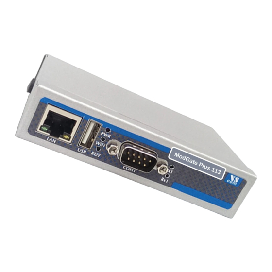
Page 8: Device Specific Characteristics
Figure 1: ModGate Plus 113 on DIN Rail This is the ModGate Plus 113 with the serial connector, Ethernet port and USB for optional WLAN expansion. The configuration switches, power connector and Reset hole are on the rear side. Also visible are two positions for a WLAN antenna, when the internal module is installed. -
Page 9: Modgate Plus 213
WLAN expansion. The configuration switches, power connector and Reset hole are on the back side (same as ModGate Plus 113). Visible on the left is the position for a WLAN antenna if the integrated module is installed. There is another positon for this antenna on the back side. -
Page 10: Modgate Plus 413
(b) Rear Side Figure 3: ModGate Plus 413 This is the ModGate Plus 413. The front side presents the four serial ports, Ethernet connector and the position for WLAN antenna with the integrated module. The rear side shows the Reset hole, the USB port for WLAN extension, configuration switches and the power supply. -
Page 11: Modgate Plus 813
(b) Rear Side Figure 4: ModGate Plus 813 This is the ModGate Plus 813. The front side presents the eight serial ports, Ethernet connector and the position for WLAN antenna with the integrated module. The rear side is the same as on... -
Page 12: Packing List
• WLAN Antenna for Models with integrated module Warning The packages of ModGate Plus 19-inch models include a Wall Mount Kit. There are two sets of screws in the package, long screws and short screws. The short screws are designed to fix the Wall Mount Kit. -
Page 13: Hardware Description
Off Table 6: Switch Configurations By default the ModGate Plus Gateway uses DHCP to get a valid IP Address. When the Gateway is configured for a static but now unknown address, one can switch to Configuration IP temporarily setting it to 192.168.254.254. Then access via webbrowser is possible for final configuration. If DHCP fails it will also respond on 192.168.254.254. -
Page 14: Rs485 Electrical Configuration
first characters of a beginning communication. The serial ports of the ModGate Plus Gateways do not require adding BIAS. This function can be added to the cable for other hardware on the RS485 bus. -
Page 15: Wlan Antenna
LED will blink. It depends on your network whether a 100 Mbit or a 10 Mbit connect will be established. A 100 Mbit net causes the Speed LED on ModGate Plus (green) to light, otherwise it will remain dark. -
Page 16: Power Supply
Table 11: Green LED Function 3.6. Power Supply The ModGate Plus device is powered by a single 9-54V power supply. It requires 300 mA up to 600 mA of current, depending on the device type and voltage supplied. A suitable power supply adapter is available as optional accessory. -
Page 17: Setup
Modbus devices. Example may be of interest. • Two ModGate Plus may also solve the problem of distance between serial Master and Slave with a tunnel using available TCP/IP infrastructure. See 8.4. - Page 18 3. Configure allowed Inbound TCP connections under Configuration of TCP Connections. a) Gather IP addresses or Hostnames which should have access to the ModGate Plus. b) Write these into the TCP conections table as Inbound connections. 4. Does your setup include Modbus/TCP Slaves?
-
Page 19: Configuration
But this is not always the situation. The ModGate Plus may use DHCP, which is also the default configuration. If a DHCP server is available, it will assign an IP Address from a configured pool. At first this address is not known to the user, since he can not access the DHCP servers log file. -
Page 20: Status
5.1.1. Status Figure 9: Status information The type of ModGate Plus is shown as the Model Name. For identification the Serial Number and MAC-Address are also given. Since such an address must be unique for all devices on the world, this is suitable to check if the configuration starts on the correct device. And last the Firmware Version is presented. -
Page 21: Network Settings
Figure 11: Access Control It is recommended to change the password to the webinterface for security reasons. The username is fixed as admin. The factory password is vscom. Note: You have to reboot the device for the changes to take effect. -
Page 22: Wlan Settings
Note: You have to reboot (see 5.1.2) the device for the changes to take effect. 5.2.4. WLAN Settings Models ModGate Plus with WLAN provide Wireless LAN as of IEEE 802.11b/g/n. This network can operate in parallel to the Ethernet. Figure 14: WLAN Radio Cell Settings WLAN Radio Cell Parameters These are the parameters to configure the radio operation, so... - Page 23 Therefore it is replaced by the mode of Access Point here, which also allows a PC to establish a direct connection to the ModGate Plus. In Infrastructure Mode all communication is sent via an Access Point on-site, which operates as the central hub of the Radio Cell.
-
Page 24: Wlan Ip Settings
Manual. If Infrastructure is chosen it is very likely Auto (DHCP) has to be used. When ModGate Plus has access to the WLAN radio cell, this network interface operates similar to Ethernet. Meaning all IP traffic operates exactly the same on Ethernet or WLAN. This results in a configuration parallel to Ethernet. -
Page 25: Online Firmware Update
If the newest firmware is already running, it will inform you of that. If the Internet is not accessible by the ModGate Plus or fails for other reasons, it shows “Getting new version info failed. Please check for a new version manually.” . -
Page 26: Modbus Configuration
DirectMappingMode operates. However in many installations there is a ModGate Plus with a single serial port only. This Gateway is contacted by only one Master via TCP. Naturally all data coming from TCP must be sent to the serial port, and vice versa. -
Page 27: Configuration Of Tcp Connections
Defined TCP connections can fulfill two separate functions: 1. They can be used to restrict the access from which IP addresses the ModGate Plus can be used. One would uncheck Allow unknown clients (See 6.3) and define all Inbound TCP connections allowed access. -
Page 28: Tcp Connections
Modbus/TCP Slaves (Server). Inbound expects a connection to the ModGate Plus on its ListenPort what a Modbus/TCP Master (Client) would do. The Port can be set for outbound connections; otherwise it will show the TCP Port on which the ModGate Plus listens. There are two types of ConnectMode available: •... -
Page 29: Modbus Gateway Settings
(Mapping of Modbus devices to serial ports or TCP connections) or LineMappingMode (Map- ping of serial ports to TCP connections). Allow unknown clients Enables all stations to connect to ModGate Plus without prior configura- tion as an allowed source for data. -
Page 30: Devices To Serial Or Tcp (Direct Mapping)
– TCP (Gateway) allows to have multiple Modbus devices on one TCP Connection because the Modbus Device ID is sent in outgoing Modbus/TCP packets. This supports TCP to serial gateways like ModGate Plus. • Destination ID: Depending on the Destination Type this is either a Serial Port ID or a TCP Connection ID. -
Page 31: Serial To Tcp (Line Mapping)
If Allow unknown clients is enabled (6.3) on a single port device, there is no need to configure a mapping. On a multi-port model all traffic from unknown clients is forwared to serial port 1. June 2018 ModGate Plus User Manual... -
Page 32: Advanced Configuration
flag, the settings belonging to the currently inactive mode are ignored (e.g. when in LineMappingMode all mappings that were specified for DirectMappingMode are ignored). ModGate Plus treats lines as comments when they start with the hash character “#”. -
Page 33: Serial Ports (Configuration Of Serial Ports)
Unique Identifier, numeric, sequentially (1, 2, ...) IP Address or hostname of the remote Modbus TCP device (e.g. “192.168.1.50”) port Port of the remote Modbus TCP device (e.g. 502) connect ConnectType (“auto” or “startup”) June 2018 ModGate Plus User Manual... -
Page 34: Mappings - Directmappingmode
# Mapping of serial ports to TCP connections tcpid 1 serialid 1 Figure 31: Manual Edit - LineMappingMode Mapping of TCP connections to serial ports tcpid Identifier of the TCP connection serialid Identifier of the serial port June 2018 ModGate Plus User Manual... -
Page 35: Special Implementation Features
Modbus/TCP as intermediate. Then these requests use the target queue as well. 7.2. Conversion of Serial Line Parameters On ModGate Plus models with multiple serial lines a master on a serial port can address slaves on the other serial ports. The DirectMappingMode allows for that configuration. The involved serial lines do not need to share the configuration parameters. -
Page 36: Example Configurations
8 Example Configurations 8. Example Configurations The ModGate Plus are intended to convert from Modbus on serial lines (RTU or ASCII) to Mod- bus/TCP, and vice versa. This chapter will show some fairly often used installation variants. The requirements of the application are given first, then the suggested configuration of ModGate Plus with an explanation on why these parameters are selected. -
Page 37: How This Works
The configuration above sends all requests coming from any TCP-Master to the first serial port. On a single port ModGate Plus this is not a problem. A multi-port device only allows to use the first serial port in this way because the information how to forward arriving requests is not specified. -
Page 38: How This Works
IP/Host is the definition of the TCP-Master to get access to a serial line. Direction is Inbound because the TCP-Master initiates the connection. Port shows 502 as the TCP port on which the ModGate Plus listens. Once such definitions exist for all planned TCP-Masters, the Line Mapping is to be defined. See... -
Page 39: Access One Or More Modbus/Tcp Devices From A Serial Master
Modbus Gateway Settings in figure 22. Select the DirectMappingMode. As the next steps for each device on Modbus/TCP the ModGate Plus needs a TCP connection defined. This is done as defined in section Configuration of TCP Connections and figure 21. -
Page 40: How This Works
Modbus Device IDs, the request is considered targeted to a device on the serial line. In that case it is ignored. But if the ID is found among the configuration, the ModGate Plus opens a TCP connection to the Modbus/TCP device if the connection does not exist yet (This is controlled by the Auto configu- ration). -
Page 41: Using Modbus/Tcp To Monitor A Serial Modbus Line
The existing serial line is cut between the Master and the Slave devices. The Master connects to serial port one of the ModGate Plus, while the remaining line with the Slaves is connected to the second serial port. The ModGate Plus will then forward the requests from the Master to the second serial port, returning the responses in the opposite direction. -
Page 42: How This Works
Plus. It extracts the Modbus ID from the request, and as per configuration this Destination ID is defined. So the ModGate Plus forwards the request to the serial port 2, where the Slave devices receive the data. The device with this Modbus ID sends the response, which in turn is forwarded back to port 1. -
Page 43: Alternatives
Gateway L for Local. Other ModGate Plus are referenced as Gateway R (R2, R3, ...) for Remote, and these are connected to the new remote devices. The ModGate Plus Gateway L is configured for Direct Mapping, and has defined TCP connections to the Gateways referenced as R. - Page 44 figure 22. The ModGate Plus Gateway L is configured for the DirectMappingMode. Next for each of the remote ModGate Plus Gateway R it needs a TCP connection defined. This is done as defined in section Configuration of TCP Connections and figure 21.
-
Page 45: How This Works
Plus Gateway L also; the Master sends requests to many Modbus IDs. When such an ID is not configured in Gateway L, the ModGate Plus simply drops the request. The target is on the serial line, and will eventually send the response. -
Page 46: Alternatives
Modbus devices communicating via RS232; in such a situation only a single device per serial port is possible. For example a ModGate Plus 413 can connect to four devices RS232, or fewer plus several other devices via RS485 on one port. -
Page 47: Troubleshooting
Figure 37: Network View (Windows 7) 3. Set the DIP switches to OFF OFF OFF OFF. Connect the PC di- rectly to the ModGate Plus using a single ehternet cable. And con- figure the PC to the static IP address 192.168.254.1/24. For that you... -
Page 48: Local Area Connection Status
Network Adapter Settings as shown in Figure 39. If multiple networks are shown, select the one corresponding to the ethernet port you like to use. When in doubt ask the local network administrator. Figure 39: Local Area Connection Status June 2018 ModGate Plus User Manual... -
Page 49: Local Area Connection Properties
192.168.254.1 as “IP address”, 255.255.255.0 as “Subnet mask” and 192.168.254.254 as “Default gateway”. Figure 41: IPv4 Properties 4. Restart the ModGate Plus. The configuration webinterface is now reachable under http://192.168.254.254. 5. Now some questions have to be answered. You may need to ask the local network adminis- trator. -
Page 50: The Green Rdy Led Blinks
9 Troubleshooting a) Does the network have a DHCP server? b) Are any restictions / policies at play that prohibit that the ModGate Plus to get an IP address? c) Was the device used in another network with a static IP? -
Page 51: The Serial Slave Does Not Response
1. Check the cabling to the Modbus/RTU or Modbus/ASCII Slave. Refer to Signal Assignment a) If RS232 is used, do the signals of TxD, RxD, GND on the ModGate Plus connect to RxD, TxD, GND on the Slave side (Strait vs Nullmodem cables)? -
Page 52: Will My Configuration Work In Practice
TCP-Master on the network: • Command for Diagslave: diagslave.exe -b 115200 -p even -m rtu COM1 - simulate a Slave on COM1 with 115200 baud and even parity acting on any Modbus ID. June 2018 ModGate Plus User Manual... - Page 53 ......• Command for Modpoll: modpoll.exe -m tcp -r 100 -c 5 192.168.1.97 - continuously request registers 100 to 104 of Slave with the Modbus ID 1 via a ModGate Plus with the IP address 192.168.1.97.
-
Page 54: History
B License A. History August 2015 Manual for ModGate Plus models April 2017 Update Firmware 2.0.7 (TCP (Gateway) mode) Added Configuration Examples January 2018 Add ModGate Mini, update menu bar, improved examples. Improved Front-End, CC license June 2018 FrontEnd updates (FW 2.1.2), Troubleshooting Section B.
Need help?
Do you have a question about the ModGate Plus and is the answer not in the manual?
Questions and answers