Table of Contents
Advertisement
Quick Links
Tel: +49 40 528 401 0
Fax: +49 40 528 401 99
Web:
www.visionsystems.de
Support:
service@visionsystems.de
User Manual
User Manual
User Manual
User Manual
User Manual
User Manual
User Manual
User Manual
User Manual
User Manual
User Manual
User Manual
User Manual
User Manual
User Manual
User Manual
User Manual
User Manual
User Manual
User Manual
User Manual
User Manual
User Manual
User Manual
User Manual
User Manual
User Manual
User Manual
User Manual
User Manual
User Manual
User Manual
User Manual
NetCom Plus
NetCom Plus
NetCom Plus
NetCom Plus
NetCom Plus
NetCom Plus
NetCom Plus
NetCom Plus
NetCom Plus
NetCom Plus
NetCom Plus
NetCom Plus
NetCom Plus
NetCom Plus
NetCom Plus
NetCom Plus
NetCom Plus
NetCom Plus
NetCom Plus
NetCom Plus
NetCom Plus
NetCom Plus
NetCom Plus
NetCom Plus
NetCom Plus
NetCom Plus
NetCom Plus
NetCom Plus
NetCom Plus
NetCom Plus
NetCom Plus
NetCom Plus
NetCom Plus
Edition: September 2016
Edition: September 2016
Edition: September 2016
Edition: September 2016
Edition: September 2016
Edition: September 2016
Edition: September 2016
Edition: September 2016
Edition: September 2016
Edition: September 2016
Edition: September 2016
Edition: September 2016
Edition: September 2016
Edition: September 2016
Edition: September 2016
Edition: September 2016
Edition: September 2016
Advertisement
Table of Contents

Related Manuals for VSCOM NetCom Plus 113


Summary of Contents for VSCOM NetCom Plus 113
- Page 1 User Manual User Manual User Manual User Manual User Manual User Manual User Manual User Manual User Manual User Manual User Manual User Manual User Manual User Manual User Manual User Manual User Manual User Manual User Manual User Manual User Manual User Manual User Manual...
- Page 2 Copyright © 2009-2016 Vision Systems. All rights reserved. Reproduction without permission is prohibited. Trademarks VScom is a registered trademark of Vision Systems GmbH. All other trademarks and brands are property of their rightful owners. Disclaimer Vision Systems reserves the right to make changes and improvements to its product without pro- viding notice.
-
Page 3: Table Of Contents
......13 2.3.2.2 NetCom Plus 113 ......14 2.3.2.3... - Page 4 Contents 4.1.1.4 Request for Trust ......31 4.1.2 Find and Configure NetCom Devices .
- Page 5 Contents 6.2.2.2.1 Driver Mode ......77 6.2.2.2.2 TCP Raw Server ......78 6.2.2.2.3 TCP Raw Client .
- Page 6 Contents 8.5.10 AT S (setup) ........102 8.5.11 AT L (loudness) .
- Page 7 List of Figures 11.2 How viaVPN solves the above Issues ......120 11.3 Configuration of viaVPN Parameters .
- Page 8 ..... . . 36 VScom drivers in the Start Menu ......36...
- Page 9 List of Figures Operation Mode by Software ....... 75 Advanced Flow Control .
- Page 10 ......13 Characteristics of NetCom Plus 113 ......14 Characteristics of NetCom Plus 211 .
-
Page 11: Overview
2 Introduction 1 Overview The NetCom Plus Serial Device Servers are designed to remotely operate serial ports over networks. The network interface is implemented as a modern Gigabit / Fast Ethernet with Auto-MDI(X). The subfamily of NetCom Plus with WLAN option Serial Device Servers provide a second network interface for WLAN (as of 802.11 b/g/n) with up to 150 Mbit/s transfer rate. -
Page 12: Features
USB–COM Plus modules . The modules provide USB-through function to add even more ports, in total there may be 16, 24, 32, ... ports. USB–COM Plus modules on VScom.de September 2016 NetCom Plus User Manual... -
Page 13: Common Characteristics
2 Introduction 2.3.1 Common characteristics Hardware Modern ARM processor WLAN antenna SMA-reverse (optional) Ethernet connector RJ45 1000Base-T/100BaseTx/10BaseT Protocols TCP/IP, UDP, SNMP, DHCP, ICMP, ARP, Telnet, RTelnet, HTTP Serial Speed 180 bps up to 3.0 or 3.7 Mbps Parity None, Even, Odd, Mark, Space Data bits 7, 8 Stop bits... -
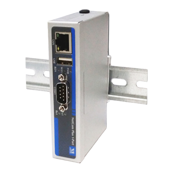
Page 14: Netcom Plus 113
Figure 1: NetCom Plus 111 / 113 The NetCom Plus 111 and the NetCom Plus 113 look the same on the front side. Here are the connectors for Ethernet, USB 2.0, LEDs and the serial port. The rear side holds the power connector, Reset button and the configuration switches. -
Page 15: Netcom Plus 211
2 Introduction 2.3.2.3 NetCom Plus 211 Two Ports. Power Requirement DC 9V to 54V, 250 mA@12V Power Connector Terminal Block (3.7.1) Serial Ports 2×RS232 Serial Speed 180 bps up to 1.0 Mbps Data bits 5, 6, 7, 8 USB Port For Expansion of Ports and WLAN Dimensions 115×73×25 mm (W×D×H) -
Page 16: Netcom Plus 411
2 Introduction connector, Reset button and the configuration switches. DIN Rail mounting clamp is fixed here. Positions for WLAN antenna are built-in. 2.3.2.5 NetCom Plus 411 Four Ports. Power Requirement DC 9V to 54V, 600 mA@12V Power Connector Terminal Block (3.7.1) Serial Ports 4×RS232 Serial Speed... -
Page 17: Netcom Plus 413 Poe
2 Introduction 2.3.2.8 NetCom Plus 413 POE Four Ports. Power Requirement DC 9V to 54V, 600 mA@15V (DC 15V to 54V on some samples) Power Connector Terminal Block (3.7.1) Power Alternative Power over Ethernet PoE 802.3af Class 0 mPCIe Slot Optional, for 3G/4G modems Orange If mobile network is available... -
Page 18: Netcom Plus 811
2 Introduction Figure 5: NetCom Plus 411 POE Rear side All models with four serial ports look the same on the front side. This side has the connectors for Ethernet and the serial ports, plus the LEDs. Also here is a plastic cap hiding the position for a WLAN antenna. -
Page 19: Netcom Plus 813
2 Introduction 2.3.2.11 NetCom Plus 813 Eight Ports. Power Requirement DC 9V to 54V, 800 mA@12V Power Connector Terminal Block (3.7.1) mPCIe Slot Optional, for 3G/4G modems Orange If mobile network is available Serial Ports 8×RS232/RS422/RS485 Serial Speed 180 bps up to 3.0 Mbps Data bits 7, 8 USB Port... -
Page 20: Netcom Plus 811 Dio
2 Introduction Figure 7: NetCom Plus 811 / 813 / 813 POE Rear side Figure 8: NetCom Plus 811 POE Rear side The above models with eight serial ports look the same on the front side. This side has the connectors for Ethernet and the serial ports, plus the LEDs. -
Page 21: Packing List
2 Introduction (a) NetCom Plus 811 DIO Front side (b) NetCom Plus 811 DIO Rear side Figure 9: NetCom Plus 811 DIO The NetCom Plus 811 DIO looks the same on the front side, as all the other models with eight serial ports. -
Page 22: Hardware Description
3 Hardware Description 3 Hardware Description This section focuses on the options provided by the hardware of NetCom Plus Serial Device Servers. 3.1 Serial Port Configuration The serial ports in the NetCom Devices follow the specifications of RS232. On many models it is also possible to use the serial ports in RS422 or RS485 mode. -
Page 23: Serial Signal Assignment
3 Hardware Description Note 1: »Configuration via Serial Port« is only effective on port 1 of the NetCom Server. Note 2: Factory Settings are restored on Power-Up/Reset of the NetCom Note 3: The Master DIP switches configure all serial ports of a NetCom to a common operation mode. -
Page 24: Rs422/485 Electrical Configuration
3 Hardware Description 3.3 RS422/485 Electrical Configuration In typical RS422 and RS485 installations certain electric conditions have to be configured. Simply connecting cables is not enough to fulfill the specifications of RS422 and RS485. For ease of installations the NetCom Plus Serial Device Servers provide the function for often used Termination. -
Page 25: Digital Input/Output
3 Hardware Description 3.5 Digital Input/Output This function is only available on NetCom Plus 811 DIO. The input signals are optically isolated from the system, and output function is realized by relay. 3.5.1 Input Connection The input uses a wet contact. There are two connector clamps per input signal, each pair marked by the number from 1 to 8. -
Page 26: Wlan Configuration
3 Hardware Description Red LED Orange LED Green LED Status Off – – Device off, no power Off Off No connection Off 1000 Mbit connection established Blink Off 1000 Mbit data transfer (traffic) 100/10 Mbit connection established Blink 100/10 Mbit data transfer (traffic) Table 17: LED Function When the firmware is completely started, the NetCom Plus becomes operational. -
Page 27: Power Supply
3 Hardware Description 3.7 Power Supply The NetCom Plus devices are powered by a single 9-54V power supply. It requires 70 mA up to 750 mA of current, depending on the device type and voltage supplied. Connect the cable to the Terminal Block at the rear side of NetCom Plus. -
Page 28: Windows Virtual Com Driver
4 Windows Virtual COM Driver 4 Windows Virtual COM Driver This chapter covers the use of NetCom Devices via Virtual Com Ports installed by the supplied driver software for Windows. Sections describe in details the process of driver installation and removal, as well as updating. This first part here is for quick installation, so only the common options are covered. -
Page 29: User Account Control (Uac)
4 Windows Virtual COM Driver 4.1.1.1 User Account Control (UAC) In modern versions of Windows OS typical configurations require to confirm the start of software to change the system configuration. (a) UAC in Windows 7 (b) UAC in Windows 10 Figure 16: User Account Control Since a change of system configuration is intended by the driver installation, confirm to start the software. -
Page 30: Proceed Installation
4 Windows Virtual COM Driver files and tools are copied to the Windows system, and installed in the Start Menu. Further the drivers are installed in the system, and the network is searched for available NetCom . The serial ports on these devices are installed as Virtual Com Ports in the system. The second option will Install Tools and Drivers. -
Page 31: Request For Trust
4 Windows Virtual COM Driver Figure 19: Copy Driver Files Some files are copied to your hard disk, this is the usual process similar to other Windows installa- tions. The upper bar increases with the progress of each step performed in the installation process. The lower bar illustrates each step performed until full installation is finished. -
Page 32: Find And Configure Netcom + Devices
4 Windows Virtual COM Driver Note: No component is actually installed at this moment. Windows is just preparing to load the drivers, once the NetCom Plus Manager instructs to do so. This request will come twice, to make it more easy just tick the Always trust option. 4.1.2 Find and Configure NetCom Devices When all files are copied, the NetCom Plus Manager... -
Page 33: Configure Ip Parameters
4 Windows Virtual COM Driver Figure 22: Discover and Select NetCom Devices for Installation After short time the search process is finished. All the discovered NetCom are listed. In your very first installa- tion of NetCom Devices and Drivers you should connect only one NetCom to your network. -
Page 34: Define Netcom + S Ip Configuration
4 Windows Virtual COM Driver Figure 24: Define NetCom s IP Configuration This panel opens. Deselect the Option of Use DHCP, and place your parameters as IP address, Netmask and Broadcast. Click on the OK button. You may also enter a DNS name instead of the IP Address. -
Page 35: Configure Firewall
4 Windows Virtual COM Driver Figure 26: Sending Parameters to a NetCom 4.1.2.2 Configure Firewall As you will notice in figure the driver may also operate by traversal of a Network Firewall. This requires a special configuration, which is skipped here. Please read in detail in section 5.5 on page 55. -
Page 36: Verify The Installation
In the Start Menu you’ll find the new pro- gram group "VScom NetCom Plus". The in- stalled programs are the NetCom Plus Manager and a Driver Repair program. Figure 29: VScom drivers in the Start Menu September 2016 NetCom Plus User Manual... -
Page 37: Update The Drivers And Tools
4 Windows Virtual COM Driver Figure 30: NetCom in Device Manager In the Device Manager the serial ports are listed in the usual section Ports. Additionally there is the device class Multi-port serial adapters. All installed NetCom Devices are listed herein. The available options are described later. -
Page 38: Configuration Of The Virtual Com Driver
4 Windows Virtual COM Driver 4.4 Configuration of the Virtual COM Driver If properly configured, the serial ports of the NetCom Devices appear as Virtual Com Ports in your computer. The "virtual" means, in the computer is no real hardware related to the serial port, however the driver offers the full functionality of a serial port to the system. -
Page 39: Performance Issues
4 Windows Virtual COM Driver The same parameters may be pre-configured in the Device Manager. This is done via the Properties of the NetCom Plus COM Port. In the Local Settings tab these standard parameters are defined. Since most programs configure these parameters by themselves, the values are very rarely used. A typical situation is a serial printer attached to this virtual port. - Page 40 4 Windows Virtual COM Driver Good Performance uses smaller blocks. The Latency may be reduced a little bit, depending on the application. But the impact on the data throughput is small. Short Latency mimics a 16C550 with full FIFO enabled, but no network timeouts will occur. This means the block size is 16, quite small for network operations.
-
Page 41: Network & Misc Properties
4 Windows Virtual COM Driver 4.4.3 Network & Misc Properties When you use the Advanced checkbox on the Performance tab, the Network/Misc tab opens automatically. Figure 33: NetCom COM Port Network/Misc Properties The parameters on this tab control the operation of the driver software on the computer. Tx Network Buffer Size: If the application sends small chunks of data to the driver, these are buffered to send them in one large packet. - Page 42 4 Windows Virtual COM Driver Overspeed: This is a special option, not really related to network communication. There are old applications, limited in the maximum speed. With Overspeed you define a multiplier. The baudrate requested by the application is multiplied with this factor. The result is sent to the NetCom to configure the serial port.
-
Page 43: Remote Settings Properties
4 Windows Virtual COM Driver 4.4.4 Remote Settings Properties The other panel created by activating the Advanced checkbox on the Performance tab, is the Remote Settings tab. Figure 34: NetCom COM Port Remote Settings Properties The parameters on this tab control the operation of the serial port on the NetCom Device. - Page 44 4 Windows Virtual COM Driver The configuration shown here is active, when the pre-defined performance levels are Enable: used. When using the ‘Advanced’ option, Remote Flow Control is completely disabled. Enable as required. While it is best practice to configure as figure 34, you can disable certain events here.
-
Page 45: Installation Of Netcom Plus Servers
4 Windows Virtual COM Driver 4.4.5 Installation of NetCom Plus Servers This section of the manual covers the correct installation of the drivers and serial ports. Please do a quick review of the section 4.1, before reading further. As of the time of writing, the current driver is version 2.0.0.0 Figure 35: Select NetCom to install... -
Page 46: Bad" Netcom
4 Windows Virtual COM Driver An icon in red color indicates possible problems. To correctly operate the virtual Com Ports the driver must establish TCP connections from the PC to the NetCom . This requires a matching configuration of IP parameters in the NetCom in the PC. -
Page 47: Changing The Installation
4 Windows Virtual COM Driver Similarly to the Exclude / Include of specific NetCom servers, you may do so with selected serial ports. Figure 41: NetCom Plus Manager Ports View Select the Ports section in the Manager. These are the special options used while installing the driver software. -
Page 48: Uninstall The Drivers And Tools
Windows operating system. On Windows 10 open Settings and therein the SYSTEM function. Select Apps & Features, and scroll down to the VScom drivers. Select this entry and click the Uninstall option. This will start the NetCom uninstallation program. -
Page 49: Remove, Repair
4 Windows Virtual COM Driver Figure 45: Uninstall NetCom Drivers in Windows 7 As an extra way on Win- dows 7 you may start the Uninstall program in the Start menu. Figure 46: Uninstall NetCom Drivers in Windows 7 Start Menu The other basic method is to start the Installation Wizard again from CD-ROM or the installation directory. -
Page 50: Configure With Netcom Manager
5 Configure with NetCom Manager 5 Configure with NetCom Manager Shipped with the NetCom Devices there is a versatile program for Windows Operating System, named NetCom Plus Manager. This program shall detect, manage and configure the NetCom Devices in your network. You can start it by several ways. First of all it is stored on the CD-ROM, named NETCOMMGRPLUS.EXE . -
Page 51: Starting Netcom Manager
5 Configure with NetCom Manager 5.1 Starting NetCom Manager When NetCom Manager is started, it will ‘Search’ the NetCom in your LAN by SNMP. This process may take up to 30 seconds. The devices in a LAN are typically found in the first seconds. If this is enough for you, you can stop the search by click on the ‘Done’... -
Page 52: Netcom Server Settings - Info
5 Configure with NetCom Manager 5.2 NetCom Server Settings – Info As described above, open the Properties of a NetCom Device. The Server Settings start with the Info panel. Configure the options as your network requires. Figure 51: NetCom Manager Server Settings - Info The Server Name is just for information. -
Page 53: Netcom Server Settings - Ports
5 Configure with NetCom Manager If address or netmask are changed, the NetCom Manager calculates a matching address for Broadcast. You may also change this address. The DHCP option will also configure the Default gateway and the Name server. Without DHCP you must enter these parameters by yourself, enter 0.0.0.0 if they are not used. -
Page 54: Netcom Server Settings - Firewall
5 Configure with NetCom Manager 5.4 NetCom Server Settings – Firewall Many networks use a Firewall to protect the stations in the network from other networks, including the Internet. In some situations the contact to a NetCom must pass through such a Firewall configured for NAT (Network Address Translation, section 15). -
Page 55: Manual Detection/Installation Of A Netcom
5 Configure with NetCom Manager 5.5 Manual Detection/Installation of a NetCom Sometimes the NetCom Device Server can not be detected by the automatic in the NetCom Manager. To detect and configure devices the protocol SNMP is used. The detection is done by sending out a broadcast on all available network interfaces of your computer. -
Page 56: Soho Virtual Servers
5 Configure with NetCom Manager 5.6.2 SOHO Virtual Servers The Router also offers "Virtual Servers" (here named ViServ for short), which is the option required for NetCom installation. These ViServ operate by a technique called PAT (Port Address Trans- lation, 15). Certain data addressed to the public IP Address of the Router are forwarded to the internal private address of the NetCom . -
Page 57: Serial Ports Through Soho Firewall
5 Configure with NetCom Manager Some ISP will block the SNMP protocol, which typically means they do not transport data for 161/udp to their customers (this is the first reason why port 8161 was used in the example). This answer brings every required information about the NetCom , including its internal IP Address. -
Page 58: Dmz And Virtual Servers
5 Configure with NetCom Manager 5.6.5 DMZ and Virtual Servers Why is it recommended not to use the DMZ function of the Router? There are two reasons. The first one is simple, only one device in the LAN can be defined as the DMZ target. The DMZ is implemented as "Send all IP data targeted for the Router to the DMZ station, unless there is a specific rule for a different target". -
Page 59: Configure The Operation Modes
6 Configure the Operation Modes 6 Configure the Operation Modes The NetCom Devices are often used without the installation of a driver software. Customer applications contact the NetCom directly, using network functions. These setups require inde- pendent configuration of the NetCom Device and the serial ports. -
Page 60: Telnet Configuration
6 Configure the Operation Modes Figure 55: Configuration Menu in Web Browser The NetCom welcomes you with its "Home" screen. To access the different options of configuration, the images above function as a link. In many menus you’ll see a blue question mark. This is a symbol for help. -
Page 61: Password Request In Telnet
6 Configure the Operation Modes For completeness the port is shown in this command. Enter the configured parameter when the port is different. If the NetCom is password protected, you need to enter the password right now. Please enter your password: Figure 57: Password Request in Telnet When connected to NetCom you must define the type of terminal used. -
Page 62: Netcom Configuration Options
6 Configure the Operation Modes Use the cursor keys to select the parameter you want to change. Hit <Enter> to edit them. Type the new value, or select provided options. Use <Esc> to leave a parameter or menu. Please check the configuration of your Telnet, if there are any problems. -
Page 63: Server Info
6 Configure the Operation Modes 6.2.1.1 Server Info Web: menu “SERVER CONFIGURATION”, section “Server Info”. Telnet: “ServerConfig”, option “Info” ServerConfig Server Info +--------------------+ Parameter Server Type Plus 113 Wireless Software Version 3.3.1 OpenVPN Hardware Version Modbus GPIO Serial Nr. 0650100420 Authentification | Date &... -
Page 64: Server Parameter Web Interface
6 Configure the Operation Modes Figure 61: Server Parameter Web Interface ServerConfig Server Parameter +--------------------+ Parameter Server Name [NetCom_0650100420] | Wireless MAC Address 74:6A:8F:00:1D:7A | OpenVPN Options auto | Modbus GPIO Interface Priority Cable, Wireless | Authentification | DHCP Enabled | Date &... - Page 65 6 Configure the Operation Modes there are Routers in the network. DNS is used to access other stations by name. The ConfigPort is used to access the NetCom for administration via Telnet. It is suggested to use the standard value for Telnet, TCP port number 23. However it may be changed for different purposes. This does not change the function of the Telnet menus.
-
Page 66: Wireless Parameter
6 Configure the Operation Modes 6.2.1.3 Wireless Parameter Web: menu “SERVER CONFIGURATION”, section “Wireless Parameter”. Telnet: “ServerConfig”, option “Wireless” This section is of course only available on the NetCom Plus with WLAN option class of devices, or when the external WLAN kit is installed. To operate a Wireless device, a lot of parameters are required. -
Page 67: Encrypted Communication
6 Configure the Operation Modes with your local regulations for the channels you are entitled to use. This manual is just informa- tive, it is in no way a reproduction of local regulations. The available CountryRegion values are FCC(1-11) for North America, ETSI(1-13) for Europe in general, SPAIN(10-11), FRANCE(10-13) and MKK(14) in Japan. -
Page 68: Viavpn Remote Management And Access
6 Configure the Operation Modes ServerConfig OpenVPN Parameter +--------------------+ Parameter You must upload the config- Wireless uration ZIP file over the OpenVPN Web-Frontend Modbus GPIO OpenVPN Authentification | Date & Time Logging Info +--------------------+ Figure 65: OpenVPN Network Parameter Of course OpenVPN may be Disabled or Enabled. When the function is active, the NetCom virtually invisible on the IP Address defined in “Server Parameter”... -
Page 69: Viavpn Network Parameter
6 Configure the Operation Modes Even non-technical users can process and manage the viaVPN solution with just a few mouse-clicks, which lets you build up your cloud-based support team without incurring elevated costs or long waiting times. ServerConfig viaVPN Parameter +--------------------+ Parameter Proxy IP Address... -
Page 70: Modbus Gpio
6 Configure the Operation Modes For easy administration of connections via the PC Client Utility the NetCom Plus provides a DHCP Server. This will assign a valid configuration to the Client Utility connection to the viaVPN system. As the result the Client PC can connect to the NetCom , and perform management operations. -
Page 71: Authentication
6 Configure the Operation Modes 6.2.1.7 Authentication Web: menu “SERVER CONFIGURATION”, section “Authentication”. Telnet: “ServerConfig”, option “Authentication” ServerConfig Security Settings +--------------------+ Parameter Password [empty] Wireless OpenVPN Modbus GPIO Authentification Date & Time Info +--------------------+ Figure 68: Access Authentification The Security Settings define a Password to restrict access to the configuration of NetCom . -
Page 72: Save
6 Configure the Operation Modes ServerConfig Date and Time Settings +--------------------+ Parameter Date & Time [01-01-2000 01:00:23 UTC+1] Wireless OpenVPN Simple Network Time Protocol Modbus GPIO Authentification | State Interval Date & Time Mode IP Address Info Interval [1800 ] +--------------------+ Server [81.7.16.58... -
Page 73: Serial Port Configuration
6 Configure the Operation Modes may discard all changes done. For many configuration changes the NetCom requires a reboot to proceed, especially if the IP parameters have been updated. The Telnet section has a separate menu for saving configurations, described later. 6.2.2 Serial Port Configuration In your web browser click on the Icon of “SERIAL CONFIGURATION”. -
Page 74: Serial Settings
6 Configure the Operation Modes 6.2.2.1 Serial Settings Web: menu “SERIAL CONFIGURATION”, column “Port N”, “Serial Settings”. Telnet: “SerialPorts”, select “Port N”, “Serial Settings” The NetCom devices allow to operate in RS422/485 modes. This is configured by the Master DIP switches or by software, PortType (current) displays the current setting. -
Page 75: Operation Mode By Software
6 Configure the Operation Modes +----------------------------+ | rs232 | rs422-4-wire | rs422-4-wire termination | | rs485-4-wire | rs485-2-wire | rs485-4-wire-termination | | rs485-2-wire-termination | +----------------------------+ Figure 73: Operation Mode by Software These are the same modes as available by configuration of DIP Switches. Using software configu- ration each port is functional independent from other ports. -
Page 76: Transfer Settings
6 Configure the Operation Modes The TxTriggerLevel operates similar for the transmission. If the defined amount is received from the network, the NetCom does not accept more data to transmit. These options reduce latency times, by increasing the network traffic. 6.2.2.2 Transfer Settings Web: menu “SERIAL CONFIGURATION”, column “Port N”, “Transfer Settings”. -
Page 77: Driver Mode
6 Configure the Operation Modes 6.2.2.2.1 Driver Mode Only very few parameters have a function in Driver Mode. NetCom is operating as a Server in TCP mode, it accepts two connections per serial port. This mode is required when the driver software for Virtual Com Ports shall be used. Mode Driver Mode TCP Port(Control) -
Page 78: Tcp Raw Server
6 Configure the Operation Modes 6.2.2.2.2 TCP Raw Server As Raw Server the NetCom operates very simple. It only waits for incoming data connections in Raw IP mode. In contrast to the Driver Mode no driver software needs to be installed on client computers, this mode operates directly on the TCP/IP stack in the operating system. -
Page 79: Tcp Raw Client
6 Configure the Operation Modes 6.2.2.2.3 TCP Raw Client Also as Raw Client the NetCom requires very few parameters. The client computer operates via the TCP/IP stack as in 6.2.2.2.2, but now the computers waits for incoming connections opened by the NetCom . -
Page 80: Null Modem Tunnel
6 Configure the Operation Modes 6.2.2.2.4 Null Modem Tunnel This operation mode is intended to build a long virtual Null Modem Cable between the serial ports of two NetCom . This mode is symmetric, both NetCom operate as server and as client at the same time. The parameters of the serial port are defined on the NetCom , as given above (3.1). - Page 81 6 Configure the Operation Modes The configuration as Server (top part) requires the same parameters as the Driver Mode, hence TCP Port(Control) and TCP Port(Data). Also the KeepAlive function operates the same. The configuration as Client (bottom) first requires a destination. Here it is given by name, but a direct IP Address may be more usual.
-
Page 82: Tcp Advanced Settings
6 Configure the Operation Modes 6.2.2.2.5 TCP Advanced Settings All of the above operation modes are special configurations for options. In some situations none of the pre-defined modes fit the customers needs. When this is the case, the TCP Advanced Settings offer the configuration of any Transfer parameter. Unusual combinations of Modes are possible with this, also standard modes with unusual parameters. -
Page 83: Udp Data Transfer
6 Configure the Operation Modes The NetCom can also operate as a network client as seen in TCP Raw Client mode. This is enabled by setting Client to On. As a client it requires the same parameter as for the specialized modes. -
Page 84: Ip-Modem
6 Configure the Operation Modes Since there is no connection, data can not be sent in a stream. UDP uses packages. There are several ways to define the content for a package. UDP MaxPacketSize is a limit for the size of UDP packets. When the amount of data received on the serial port reaches this limit, the UDP Frame is assembled and sent to the destination. -
Page 85: Print Server Function
6 Configure the Operation Modes 6.2.2.2.8 Print Server Function The NetCom firmware allows the function as a Print Server according to RFC1179, also called a »Line printer daemon«. A print server is accessed through its IP Address via one specified TCP Port (see section 6.2.1.2). Data is handled in distinct queues, each with a certain name. -
Page 86: Ping
6 Configure the Operation Modes • Saving of Configuration to / Loading from a file (web browser only). • Information logging by Syslog function and a DebugLog via TCP/IP. In your web browser click on the Icon of “TOOLS”, the browser opens the list of available tools. In Telnet the “Tools”... -
Page 87: Statistics
6 Configure the Operation Modes Via Telnet use the <Esc>-key to stop the Ping function. 6.2.3.2 Statistics Web: menu “Tools”, section “Statistics”. Telnet: “Tools”, option “Statistics”. The Statistics are presented on a by-port base. So you first select the serial port, and then you get the information about modem status and control. -
Page 88: Netstat
6 Configure the Operation Modes 6.2.3.3 Netstat Web: menu “Tools”, section “Netstat”. Telnet: “Tools”, option “Netstat”. Tools +-------------+ | Ping | Statistic | Netstat | Wireless | Logging | Firmware +-------------+ Figure 88: Start Netstat Update Proto Local Address Foreign Address State 0.0.0.0:23 0.0.0.0:0... -
Page 89: Wireless
6 Configure the Operation Modes Netstat is a common tool to display the actual status of network connections. It may be used to monitor the actual status of the NetCom . This is a standard tool for network debugging. A ‘Foreign Address’ of “0.0.0.0” is listed when NetCom is waiting for an incoming connection (LISTEN mode). -
Page 90: Firmware
6 Configure the Operation Modes This example lists two other NetCom configured for Ad-Hoc communication on channel 7. Both do not use encryption. There is also an Access Point (listed as Managed), of course in Infrastructure- mode. To connect to this AP the NetCom Plus with WLAN option must use encryption. In Telnet the display is updated automatically when some information changes. -
Page 91: Save And Load Configuration
6 Configure the Operation Modes 6.2.3.6 Save and Load Configuration Web: menu “Tools”, section “Configuration File”. Via web browser it is possible to save the actual configuration to a text file. Of course it is also possible to load the saved configuration into a NetCom Figure 93: Save and Load Configuration in Web Browser This may be very useful when configuring several NetCom of the same type. -
Page 92: Save
6 Configure the Operation Modes The Syslog function may of course be Off or On. In the On-state the NetCom sends all the log information to a computer defined by Destination. A special software often called Syslog Daemon has to receive these data. The Option of Facility is a criteria for the Daemon how this will organize the data received from the NetCom In contrast for Debuglog the NetCom behaves as the server. -
Page 93: Exit
6 Configure the Operation Modes 6.2.5.2 Exit Telnet: “Save&Exit”, option “Exit”. You will not be surprised, when you leave the menu by selecting this option. If you made any changes of parameters, you must confirm to save these. Save&Exit +---------------------------------+ +------------------+ | Do you want to save the changes | | Save Parameter |... -
Page 94: Operation In Linux
For the following sections the IP Address 192.168.1.198 is used, with 2001 as the TCP data port number. This may be the serial port of a NetCom Plus 113 serial device server. 7.1 Via Fixed TTY Pseudo Serial Port (socat) There are applications designed to operate via serial ports, and via this only. -
Page 95: Via Tcp Raw Server Mode
7 Operation in Linux 7.2 Via TCP Raw Server Mode The application will use the IP Address of the NetCom with the configured TCP port number for the intended serial port. Usually the first serial port uses 2001 as TCP data port, so as an example program here is the command line for telnet application: t e l n e t 1 9 2 . -
Page 96: Ip Modem Function
8 IP Modem Function 8 IP Modem Function The Firmware offers the function of IP Modem. Used in this mode, the serial port of the NetCom emulates a standard serial modem. Basically this means the NetCom will a) answer to AT-commands on the serial port b) establish a connection to a destination c) inform the connected serial device of the connection d) accept a TCP connection, and inform the serial device of that event... -
Page 97: Operation Modes By Ip Modem
8 IP Modem Function The recommended cable connects as shown in this table. Please note, this installation does not use the simply crossed signals. Especially the DSR of the PC is internally connected to the DTR of the PC. DB9m IP-Modem DB9m DB9f... -
Page 98: At Command Set
8 IP Modem Function 8.4.1 AT command set The following table lists many standard commands (in alphabetical order). The AT is omitted for brevity. The discussion of the functions is below the tables in section below. 8.4.1.1 Standard AT-Commands These commands are based on the old Hayes Modem. Hayes-Standard IP Modem Function Answer Call... -
Page 99: Non-At Commands
8 IP Modem Function 8.4.1.3 Non-AT commands All these commands apply in Command Mode. If a Dial command or an ATA succeeds with a CONNECT, the IP Modem is in data mode. Every data received on the serial port is sent to the other station/IP Modem. And there is a special character sequence in Data Mode, which changes back to Command Mode. -
Page 100: At D (Dial)
All other non-numeric characters are understood as modifiers. The IP Modem will simply ignore them. This especially applies to space characters. Typically dial strings are: ATDT192,168,254,254,2003<cr> Dial another IP Modem as a Modem-to-Modem AT&Z12=demokit.vscom.com.tw:23<cr> Define a shortcut for configuration port ATDPS12<cr> Dial the other IP Modem as Modem-to-Host Table 23: IP Modem Sample Dials 8.5.2 AT O (online / data mode) -
Page 101: At E (Echo) [Ate1]
8 IP Modem Function ATB0 Modem-to-Host mode ATB1 Modem-to-Modem mode, which is the default ATB2 Modem-to-Modem when Touch Tone dialing, Modem-to-Host when Pulse dialing. Answer in Modem-to-Modem. ATB3 Modem-to-Modem when Touch Tone dialing, Modem-to-Host when Pulse dialing. Answer in Modem-to-Host. Table 24: IP Modem virtual Modulation 8.5.5 AT E (echo) [ATE1] Disable and enable the echo of the commands received. -
Page 102: At S (Setup)
8 IP Modem Function ATI or 230.4kbps maximum ATI0 ATI1 100000000 100Mbps Ethernet ATI2 ATI3 Version 1.0 / <compile-date> Version of Modem-Firmware ATI4 Current Profile ATI5 ATI6 NetCom 230k IP-Modem Device Identification ATI7 ATI8 ATI9 (<Name>\Serial#\IP-#:port\Com-X\NetCom) Display serial port used ATI10 ATI11 <very extended information>... -
Page 103: At &F (Factory Settings) [At&F0]
8 IP Modem Function 8.5.15 AT &F (factory settings) [AT&F0] This command has historically been designed as "Reset to Factory settings", while ATZ simply meant reset. At time of invention users could change the default behavior of their Modem, so ATZ activated the stored profile. -
Page 104: At &K (Handshake) [At&K3]
8 IP Modem Function 8.5.19 AT &K (handshake) [AT&K3] or as alternative command . . . 8.5.20 AT \Q [AT\Q3] Configure serial Flow Control. AT&K0 and AT\Q0 disable all Flow Control. The default is AT&K3 and AT\Q3 to use RTS/CTS Hardware Flow Control between PC and IP Modem. AT&K4 and AT\Q1 configure for XON/XOFF Software Flow Control between PC and IP Modem. -
Page 105: Init String Definition
9 Print Server Operation 9 Print Server Operation Sometimes the Serial Device Servers are used together with serial printers. These printers are available via a network to several stations for printing. So far there have been two operation modes to achieve this. First the serial port can operate as a TCP Raw Server, and the station just sends the data to print via a TCP connection. -
Page 106: Ascii Text
9 Print Server Operation 9.2.1.1 ASCII Text Ordinary ASCII characters are entered as they are on the keyboard. The single exception is the ’Less Than’ character ’<’, which is used for other special functions. 9.2.1.2 ASCII Control Codes ASCII control codes are entered by their standard name, enclosed in ’Angle Brackets’, i.e. -
Page 107: Add A New Printer
9 Print Server Operation 9.3 Operation in Windows® The Printer Server mode may be used to support serial printers in Windows® Operating System. This is a short instruction how to install and use it. Experience on installing printers in Windows is required for this instruction. -
Page 108: Name The New Printer Port
9 Print Server Operation Figure 100: Create Printer Port In the »Add Standard TCP/IP Port« Wizard just click the "Next" button, and have the NetCom Serial Device Server properly configured for LPD-operation. 9.3.1.2 Name the new Printer Port Then the properties of the new printer port must be en- tered. -
Page 109: Configure The Printer Port
9 Print Server Operation 9.3.1.3 Configure the Printer Port As the last step in creating the printer port for your printer you need to enter some additional information. As the »Device Type« select "Custom", and open the "Settings . . . ". Figure 102: Mode-Properties of Print Server Port Under »Port Settings«... -
Page 110: Add The Print Server Port
9 Print Server Operation Figure 103: Select Port for Printer Select the installed printer, and open the properties. In the properties select the tab for »Ports«. 9.3.2.2 Add the Print Server Port The button for "Add Port. . . " opens a dialog with the possible printer port types. -
Page 111: Openvpn Installation Wizard
10 OpenVPN™ Encryption 10 OpenVPN™ Encryption The NetCom Plus Serial Device Servers offer a special method of encrypted communication. Instead of modifying driver and application programs to support encryption (e.g. by using SSL), the NetCom Plus Servers provide a virtual direct network connection between the computer and the NetCom Plus. -
Page 112: Netcom Openvpn Configuration
10 OpenVPN™ Encryption While installing all components, the Installation Wizard has to install a new driver for a virtual network card. Since Windows XP drivers are not only digitally signed, the system also requests either a valid signature or explicit confirmation of installation by the administrator. This time it is about the »TAP-Win32 Adapter«... -
Page 113: Openvpn Client Configuration File
10 OpenVPN™ Encryption 10.3 OpenVPN™ Configuration OpenVPN may be started in several ways. One option is the command line, which has the most flexibility. A service for OpenVPN is also installed, it will open the connection without user intervention. The next option is to use the Context-Menu of the configuration file, and finally the Graphical User Interface (GUI) installed with many modern software packages for OpenVPN. -
Page 114: Openvpn Server Configuration File
10 OpenVPN™ Encryption The configuration file must be named config.ovpn and put together with all other files (preserving the /data/ directory if used) into a standard ZIP file, which must be uploaded over the web-frontend. This is an example content of a ZIP file: •... -
Page 115: Start Netcom Plus With Openvpn™ Active
10 OpenVPN™ Encryption 4. Call the commands vars.bat, clean-all and build-ca in this order. You could press enter for all the values for which you will be asked, except the Common Name, which should be the name of your VPN (eg. MyVPN). 5. -
Page 116: Start Openvpn™ By Command Line
10 OpenVPN™ Encryption Figure 111: Context-Menu of OpenVPN™ The Context-Menu is available via right click on the file. Select the action "Start OpenVPN" to open the connection to the NetCom Plus. This will start the openvpn.exe program in the "bin"-subfolder of OpenVPN. -
Page 117: Start Openvpn™ As Windows Service
10 OpenVPN™ Encryption CD "Program files\OpenVPN\config" ..\bin\openvpn --config "client.ovpn" Figure 113: OpenVPN by Command line There will be a lot of text output, after some seconds it will read as: Initialization Sequence Completed At this stage the network connection becomes active and usable. Use TELNET or PING to test the connection from a second console window. -
Page 118: Startup Types
10 OpenVPN™ Encryption The Installation Wizard also installed a Windows Service for OpenVPN in the Services applet of the Control Panel. The Startup Type is defined as "Manual", so it does not start without special user interaction or required by a dedicated application. When the openvpn.exe program is started by means of this service, it scans the "config"-subfolder for configuration files of type ".ovpn". -
Page 119: Reconfigure Virtual Serial Ports For Openvpn
10 OpenVPN™ Encryption The configuration is much more simple, the Router does not need to have a lot of detailed data. All the different connections required between the Client computer and the NetCom Plus to use the Serial Device Server are carried via this single OpenVPN™ connection in TCP mode. When OpenVPN™... -
Page 120: How Viavpn Solves The Above Issues
11 viaVPN Remote Access System 11 viaVPN Remote Access System The paragraph 6.2.1.5 on page 68 mentions the option of viaVPN. Since this is only available in some models of NetCom Plus, the description of this system is delegated to this chapter entirely. 11.1 Obstacles when used via Internet When a NetCom Plus is used via the Internet, it requires a public IP Address or at least some configuration of the Firewall at the location of the NetCom... -
Page 121: Configuration Of Viavpn Parameters
11 viaVPN Remote Access System In addition to the easy handling of devices, PCs and connections, all connections to the viaVPN system use strong and modern encryption. This prevents all eavesdropping by any party. Even more important it provides strong means of authentication, which ensures only the customer decides on who has access to the NetCom Plus. -
Page 122: Ready Led With Viavpn
11 viaVPN Remote Access System not just on, instead it blinks in a slow pace (symmetric On and Off). When the connection to the Rendezvous Server is established, the Ready LED is permanent On. When a Client PC is connected via the Utility, this is also signaled by the Ready LED. This time the LED light is interrupted (short time Off, most time On). -
Page 123: Modbus/Tcp For Digital-Input/Output
12 Modbus/TCP for Digital-Input/Output 12 Modbus/TCP for Digital-Input/Output The operation of the Digital-Input and -Output signals is based on libmodbus software. This is also a library which you may use in your application to communicate with the NetCom Plus. In the NetCom Plus it supports communication via Modbus/TCP protocol as a Slave device to control digital input and output signals. -
Page 124: Examples
12 Modbus/TCP for Digital-Input/Output 12.2 Examples 12.2.1 Read two input signals Function Read Coils is native to get the status of input signals. Here we read the status of Input 2 and 3, to see if the two pins of each are connected to each other or not. Request: Function Code one byte... -
Page 125: Tcp/Ip Description
13 TCP/IP Description 13 TCP/IP Description TCP/IP is the protocol used on the Internet, and in local networks as well. This opens access to any device connected somewhere to the Internet. But a simple contact like plugging in a cable is not enough. -
Page 126: Automatic Configuration (Apipa)
13 TCP/IP Description 13.1.3 Automatic Configuration (APIPA) A different type of automatic configuration is used by Windows. If a station is prepared for automatic settings, it will search for a DHCP server (see above). But in SOHO networks this server might not exist. Windows detects this failure, and the computer self-assigns an IP Address. -
Page 127: Troubleshooting Guide
14 Troubleshooting Guide 14 Troubleshooting Guide The most common problems when using NetCom are caused by a failure in the configuration of network parameters. This is a list of some symptoms, and tests to check them. 1. First examine the network configuration of your computer. Open a console window (MSDOS command prompt), and use the command IPCONFIG /ALL to retrieve the information. - Page 128 (http://www.vscom.de/). 11. In rare cases or on special hardware the driver for Windows may have a problem. Please load and install the latest version (http://www.vscom.de/) and try again. It is necessary to uninstall the previous version.
-
Page 129: Glossary Of Terms
15 Glossary of Terms 15 Glossary of Terms AES: Advanced Encryption Standard The successor of the now insecure DES. AES provides strong and modern encryption, with long keys up to 256 Bit (DES used 56 Bit). APIPA: Automatic Private IP Addressing A scheme to self-assign an Address to a network device. - Page 130 15 Glossary of Terms Netmask: Groups stations to a Net The AND-operation between the IP Address and the Mask is an important value. When to stations have the same result and the same mask, they are "in the same net". Which means they can communicate direct, without transmitting to a Router.
-
Page 131: History
16 History UPnP: Universal Plug and Play Devices announce their presence on the network, and return their capabilities on the network. Depending on the type of device certain configuration is done, specific functions become avail- able. Specialized software can detect those devices, and offer their services without manual config- uration. - Page 132 16 History September 2016 Operation Modes corrected Firmware Version 3.3.5 September 2016 NetCom Plus User Manual...
Need help?
Do you have a question about the NetCom Plus 113 and is the answer not in the manual?
Questions and answers