Curtis WB5GT Series User Manual
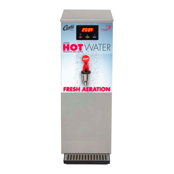
5 gallon water boiler
Hide thumbs
Also See for WB5GT Series:
- Service manual (8 pages) ,
- Instructions manual (7 pages) ,
- Specification sheet (2 pages)

Subscribe to Our Youtube Channel
Related Manuals for Curtis WB5GT Series


Summary of Contents for Curtis WB5GT Series
- Page 1 USER GUIDE WB5GT Series 5 Gallon Water Boiler READ AND SAVE THESE INSTRUCTIONS NOTICE TO INSTALLER: Please leave this booklet with the machine.
-
Page 2: Table Of Contents
..................................................ES97 ..........................ES98 ..........................ES99 ............................................................EC9 ..............................Contact Information Wilbur Curtis Co., Inc. 6913 Acco Street | Montebello, CA 90640 US Phone: 323-837-2300 | Toll Free: 800-421-6150 Email: csrassistance@wilburcurtis.com | Web: www.wilburcurtis.com . - 4:00 . PT Email: techsupport@wilburcurtis.com... -
Page 3: Fs54
KEY FEATURES/SPECIFICATIONS/SYSTEM REQUIREMENTS FS54 Key Features • G3 Digital Control Module – Provides precise control of temperature. • • Easy-To-Operate – Simple graphics for all operating functions and ready lights. • Energy Savings Mode – 4 hours after last dispense, tank will maintain temperature of 140°. •... -
Page 4: Is2
• This appliance is designed for commercial use. Any service other than cleaning and preventive maintenance should be performed by an authorized Wilbur Curtis service technician. • To reduce the risk of re or electric shock, DO NOT open the service panels. There are no user serviceable parts inside. - Page 5 IMPORTANT SAFEGUARDS CE Requirements • This appliance must be installed in locations where it can be overseen by trained personnel. • For proper operation, this appliance must be installed where the temperature is between 5°C to 35°C. • This appliance is not suitable for outdoor use. •...
-
Page 6: Ii20
INSTALLATION INSTRUCTIONS II20 WARNING: WARNING: properly grounded. NOTICE: SPECIFICATIONS section. IMPORTANT: Installation Instructions Installation Requirements • A secure surface capable of supporting the weight of the appliance. • For units without an attached cord set: Appropriately sized, UL listed, grounding type power cable to meet enough •... -
Page 7: Ii27
INSTALLATION INSTRUCTIONS II27 Installation NOTICE: Before proceeding, make sure that the counter is capable of supporting at least 81 lbs. (37 kg) to allow for the water boiler at full capacity. Leveling WARNING: Use the leveling legs to level the unit only. - Page 8 INSTALLATION INSTRUCTIONS II27 Connecting the Power Cord to A Junction Box (if applicable) If the power cord will be connected directly to the junction box, connect the power cable wires to the terminals in the junction box. See the ELECTRICAL SCHEMATIC for the power supply requirements.
- Page 9 INSTALLATION INSTRUCTIONS II27 Powering up the Unit (cont.) All Units: 12 Make sure that the circuit breaker supplying power to the circuit is on. 13 Turn on the water supply valve. 14 Turn the toggle switch on the back of the unit to the ON Style varies 15 Check the water supply line for leaks.
-
Page 10: Oi40
• Press the AERATION (AIR) button to manually pump air through the water in the heating tank any Control Panel - WB5GT Series time you want. The aerator pump will run as long as you hold down the button. READY... - Page 11 READY READY TEMP ON/OFF AERATION Control Panel - WB5GT Series Control Panel - WB5N Series Programming Options Temperature (default is 204° F/96° C) Press the TEMP button for one second to check the control panel water temperature setting. To change...
- Page 12 CLEANING INSTRUCTIONS CI16 WARNING: HOT SURFACES - To avoid injury, allow the unit to cool 30 minutes before cleaning. NOTICE - Do not use cleaning liquids, compounds or powders containing chlorine (bleach) or corrosives. USE OF THESE PRODUCTS WILL VOID THE WARRANTY.
- Page 13 ROUGH-IN DRAWINGS RD60 WB5GT 22.20 in [56.4 cm] 16.61 in 9.11 in [23.1 cm] [42.2 cm] 24.52 in 3.50 in [62.3 cm] [8.9 cm] 12.70 in [32.3 cm] 13.55 in [34.4 cm] WB5GT, ROUGH-IN DRAWING 021320A...
- Page 14 ILLUSTRATED PARTS/RECOMMENDED PARTS IP99 WB5GT - Main Chassis - Exploded View Water tanks assemblies: - See section IP100 for single phase models - See section IP101 for three phase models WB15GT, ILLUSTRATED PARTS/RECOMMENDED PARTS 022518NC...
-
Page 15: Ip99
WC-314 POWER BLOCK, 5 STATION 125/6A 250VAC RESISTIVE KIT, FAUCET ASSY, RED HANDLE 1-1/32-14 SWITCH, TOGGLE NON-LIT DPST 25A WC-1800HWK WC-103 2,3 UNS CURTIS 125/250VAC RESISTIVE CAPACITOR, X2 USED ON ALL ADS WC-8591 1,3 WC-61549 COVER, SIDE ACCESS WB5GT MODELS RELAY, SOLID STATE, 280Vac MAX W/ CAPACITOR, 2.2 UF 250/275 VAC 50/60 ALL... - Page 16 ILLUSTRATED PARTS/RECOMMENDED PARTS IP100 WC-62045 - Tank Assembly Water Level Probe Detail (Older Units) WC-62045 - Tank Assembly - Parts List ITEM # PART # DESCRIPTION ITEM # PART # DESCRIPTION WC-62045 TANK, COMPLETE WB5GT63 THERMOSTAT, HI LIMIT HEATER CONTROL DPST WC-522* 277V 40A WC-5661...
- Page 17 ILLUSTRATED PARTS/RECOMMENDED PARTS IP101 WC-62044 - Tank Assembly, 3 Phase Water Level Probe Detail (Older Units) WC-62044 - Tank Assembly - Parts List ITEM # PART # DESCRIPTION ITEM # PART # DESCRIPTION WC-62044 TANK, COMPLETE WB5GT19 THERMOSTAT, HI LIMIT HEATER CONTROL DPST WC-522 277V 40A WC-5661...
-
Page 18: Es97
ELECTRICAL SCHEMATICS ES97 WB5GT63000/WB5N Series - Dual Voltage UCM Pin Assignments 16 Pin Connector UCM GROUND WATER LEVEL PROBE NOT USED NOT USED SOLID STATE RELAY - (+5Vdc) NOT USED ELECTRICAL RATING TABLE TANK TEMPERATURE SENSOR # of Tank Element Voltage Amps Wa s... -
Page 19: Es98
ELECTRICAL SCHEMATICS ES98 WB5GT/WB5N - 3 Phase WB5GT-19, ELECTRICAL SCHEMATIC 022818NC... -
Page 20: Es99
ELECTRICAL SCHEMATICS ES99 WB5GT/WB5N - 220-240 Volt, Dual Element UCM Pin Assignments 16 Pin Connector UCM GROUND WATER LEVEL PROBE NOT USED NOT USED SOLID STATE RELAY - +5Vdc NOT USED TANK TEMPERATURE SENSOR TANK TEMPERATURE SENSOR NOT USED NOT USED INLET VALVE AIR PUMP 230V L1... - Page 21 TROUBLESHOOTING GUIDE TG32 WARNING: Electric Shock Hazard - Scald and Burn Hazard - IMPORTANT: always Valve Test Procedure Troubleshooting Guidelines If an error message appears on the display, consult the ERROR CODES • • • Use this troubleshooting guide along with the appropriate ELECTRICAL SCHEMATIC. •...
- Page 22 TROUBLESHOOTING GUIDE TG32 Sensor Error Message (ERR1) Water Level Error Message (ERR2) ERROR CODES Water Tank Water Does Not Heat At All Tank Does Not Fill • If the water heats, but is not hot enough, see Water Not Hot Enough •...
- Page 23 TROUBLESHOOTING GUIDE TG32 Water Too Hot (Boiling or Excessive Steaming) IMPORTANT: Aeration (Air) Does Not Work Water Tank Does Not Fill IMPORTANT: WB5, TROUBLESHOOTING GUIDE 010518NC...
-
Page 24: Ec9
ERROR CODES System Fault Messages An error message will appear on the screen in the event of a malfunction under the following conditions: ERROR MESSAGE WARNING DESCRIPTION CAUSE ERR1 ERR2 WB5, ERROR CODES 010518NC... - Page 25 Return Merchandise Authorization (RMA): All returned equipment must be properly re-packaged in the original carton and received by Curtis within 45 days following the issuance of a RMA. NO UNITS OR PARTS WILL BE ACCEPTED WITHOUT A RETURN MERCHANDISE AUTHORIZATION (RMA).
Need help?
Do you have a question about the WB5GT Series and is the answer not in the manual?
Questions and answers