Advertisement
Quick Links
GUIDA ALL'INSTALLAZIONE
INSTALLATION GUIDE
INSTALLATIONSANLEITUNG
NOTICE D'INSTALLATION
GUÍA PARA LA INSTALACIÓN
D703
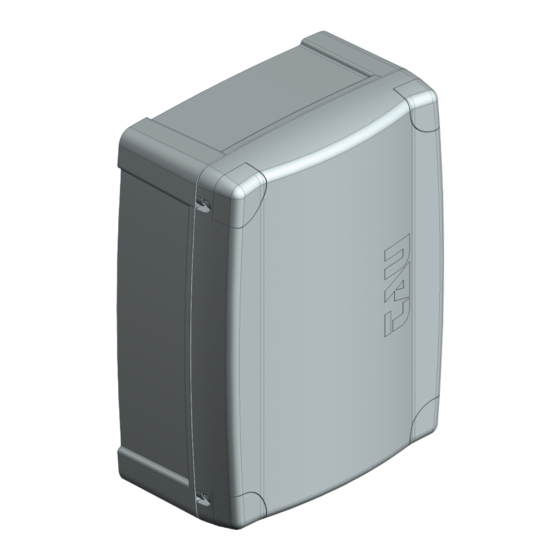
Quadro di comando per motore monofase-trifase 230/400 Vac
Control panel for 230/400 Vac single/three-phase motor
Steuerplatine für einphasigen-dreiphasigen 230/400 Vac Motor
Logique de commande pour moteur monophase-triphase 230/400 Vca
Panel de mandos para motor monofásico-trifásico 230/400 Vca
230
124
300
IT - Istruzioni originali
Via Enrico Fermi, 43 - 36066 Sandrigo (VI) Italia
Tel +39 0444 750190 - Fax +39 0444 750376
info@tauitalia.com - www.tauitalia.com
D703
1
Advertisement

Summary of Contents for tau D703
- Page 1 GUIDA ALL’INSTALLAZIONE INSTALLATION GUIDE INSTALLATIONSANLEITUNG NOTICE D’INSTALLATION GUÍA PARA LA INSTALACIÓN D703 Quadro di comando per motore monofase-trifase 230/400 Vac Control panel for 230/400 Vac single/three-phase motor Steuerplatine für einphasigen-dreiphasigen 230/400 Vac Motor Logique de commande pour moteur monophase-triphase 230/400 Vca Panel de mandos para motor monofásico-trifásico 230/400 Vca...
- Page 2 Common Open Close Common Stop Common Open Close Common Fixed safety edge Photocell Common MASTER 20T BIG18QI Thermal protector D703...
- Page 3 OLS = Open limit switch CLS = Close limit switch O/C =Open/Close Ped = Pedestrian Cap = Capacitor TX = Transmitter RX = Receiver M = Motor COM = Common ENC = Encoder 400Vac VOLTAGE SELECTION 230Vac Antenna Gate open warning light max.
- Page 4 This product may only be installed and serviced by qualiied personnel in compliance with cur- rent, laws, regulations and directives. When designing its products, TAU observes all applicable standards (please see the attached declaration of conformity) but it is of paramount importance that installers strictly observe the same standards when installing the system.
-
Page 5: Technical Characteristics
Flashing frequency increas- es slightly during closing; STOP button input (normally closed contact); this stops the 9 - 10 STOP automatic system. At the next command, the opposite opera- tion to the previous one is performed (common=9); D703... - Page 6 AERIAL input (earth=31, signal=32) (only for RX 40.665MHz); 31 - 32 AERIAL RADIO CHANNEL output; Warning: to connect other devices to the 2nd Radio 33 - 34 RADIO CH Channel (area lighting, pumps, etc.), use an additional auxiliary relay (with receiver connected). RECEIVER radio board connector. D703...
- Page 7 BRAKING braking disabled; Note: the braking system activates whenever the motor must stop (FCC - FCA - STOP – change of direction) and reduces the inertia accumulated by the gear motor during movement. D703...
- Page 8 Check the state of the radio control batteries. The gate opens the wrong way a_ Invert the motor connections on the terminal block (terminals 5 and 6); Consequently, invert the connections of the limit switches (terminals 20 and 21). D703...
- Page 9 2. The motor wires connected at terminals 4, 5 and 6 on the D703 need to be connected to terminals U, V and W on the inverter. 3. You will need two 240 volt relays. Connect terminal 4 (COM) on the D703 to one side of the coil of both relays.


Need help?
Do you have a question about the D703 and is the answer not in the manual?
Questions and answers