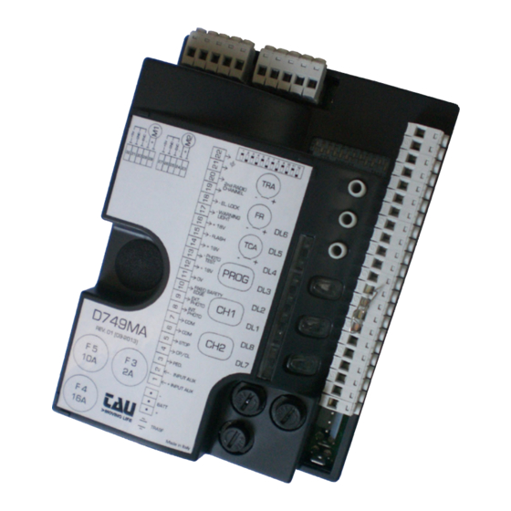
tau D749MA Installation Manual
Control panel for one-two 18v motors with encoder
Hide thumbs
Also See for D749MA:
- Installation manual (77 pages) ,
- Installation manual (68 pages) ,
- Installation manual (19 pages)
Table of Contents
Advertisement
TIP – The D749MA control board is a purpose made control board for TAU five wire motors. The
easiest cable to use from your motor to the control board is five core trailer cables. It is low voltage
cable and available at your Automatic Solutions branch or major automotive stores. Use red and
black for your motor/s and the other three for your encoder connections.
TIP – Always concentrate on connecting your motor/s and programming these first before adding
any accessories. Accessories like keypads and photocells should be added one at a time after you
TIP – You need to fit four small loops of wire to your safety inputs to make anything work. These
need to be removed later if you install safety devices to these input terminals. But for now take
four pieces of light gauge wire (speaker or telephone wire is good) about 40mm long and strip both
ends 7mm. Insert them from terminals 5 to 6, 7 to 8, 7 to 9 and 7 to 10.
TIP – If you have performed the previous step correctly when the board is powered you will have
TIP – A good starting setup for your dip switches on single gates is 8 on – all others off.
TIP – A good starting setup for your dip switches on double gates is all switches off.
TIP – You must have good physical stops in both opening and closing. The D749MA uses these stops
TIP – During programming if either or both gates do not open as the first movement simply stop the
programming and at the control board reverse the red and black motor wires of the motor/s going
the wrong way. Then power back up and restart programming.
Q u e s t i o n s – s e r v i c e @ a u t o m a t i c s o l u t i o n s . c o m . a u
LOGICTAUD749MA
have your gates setup and operating correctly.
four green LED's lit. DL3, DL4, DL5 and DL6.
during programming and operation.
Page 1
Advertisement
Table of Contents

Related Manuals for tau D749MA


Summary of Contents for tau D749MA
- Page 1 LOGICTAUD749MA TIP – The D749MA control board is a purpose made control board for TAU five wire motors. The easiest cable to use from your motor to the control board is five core trailer cables. It is low voltage cable and available at your Automatic Solutions branch or major automotive stores.
- Page 2 INSTALLATIONSANLEITUNG NOTICE D’INSTALLATION GUÍA PARA LA INSTALACIÓN GUIA DE INSTALAÇÃO D749MA Quadro di comando per uno/due motori 18V con encoder Control panel for one-two 18V motors with encoder Steuerplatine für einen (zwei) 18V Motor(en) mit Encoder Logique de commande pour un ou deux moteurs 18V avec encodeur...
- Page 3 SCHEMA CABLAGGIO D749MA / D749MA WIRING DIAGRAM / SCHALTPLAN DER Dip-switches 9 10 11 12 9 10 11 12 D749MA FIXED SAFETY EDGE PROG EXT. PHOTO INT. PHOTO STOP OPEN/CLOSE Power supply by transformer PEDESTRIAN ERRORS External power supply DL7 BATT...
- Page 4 D749MA / SCHÉMA CÂBLAGE D749MA / ESQUEMA DEL CABLEADO D749MA Aerial Gate open warning light E.L. max. 3W 18V 15W Flashing External 2nd radio light Photocells channel 18V DC 1 2 3 4 5 max. 20W + 18 V + 18 V...
- Page 5 MANUFACTURER’S DECLARATION OF INCORPORATION (in accordance with European Directive 2006/42/EC App. II.B) Manufacturer: TAU S.r.l. Address: Via E. Fermi, 43 36066 Sandrigo (Vi) ITALY Declares under its sole responsibility, that the product: Electronic control unit designed for automatic movement of:...
- Page 6 This manual is designed to assist qualiied installation personnel only. It contains no informa- tion that may be of interest to inal users. This manual is attached to the D749MA control unit, therefore it may not be used for different products! Important warnings: Disconnect the mains power supply to the board before accessing it.
- Page 7 TAU cable code M-03000010C0 to connect the motors to the control board. INTRODUCTION The D749MA board has two working modes, selectable through the J6 jumper (see wiring diagram). J6 Jumped: standard mode, i.e. the control unit is powered all the time;...
- Page 8 (M2) supply output 18V DC max. 50 W. 23 - 24 MOTOR (M2) (23= POSITIVE - 24= NEGATIVE) encoder supply and input (25= WHITE signal - 26= BLUE 25 - 26 - 27 ENCODER (M2) negative - 27= BROWN positive) D749MA...
- Page 9 No. 2. the pre-lashing function is enabled. PRE- the pre-lashing function is disabled. FLASHING the “photocell test” function is enabled. the “photocell test” function is disabled. FOTOTEST Note: to be used when the photocells are not used. D749MA...
- Page 10 AP/CH control, the remote control (if programmed) or press the PROG button briely. Please remember that an obstacle during saving is interpreted as a mechanical limit stop (the system does not start any safety operation, it just stops the motors). Make sure you don’t stand near the automation during saving. D749MA...
- Page 11 D749MA CHARACTERISTICS TIMER-OPERATED OPENING AND CLOSING CYCLES The opening/closing of the automation can be controlled by means of a timer that has a free N.O. output contact (relay). The timer must be connected to terminals 4 - 6 (OPEN/CLOSE button) and can be programmed so that, at the desired opening time, the relay contact closes until the desired closing time (when the timer’s relay contact opens, enabling the automatic closing of the gate).
- Page 12 (green): CH1 channel memory full; channel CH2 waiting to be saved; always on (yellow): fast lashing (yellow): CH2 channel memory full; lashing (green): CH1 channel waiting to be cancelled; always on (green): cancelling of channel CH1 in progress; D749MA...
- Page 13 8_ to exit the learning mode without memorising a code, press button CH1 or CH2 briely. If the maximum number of radio controls is reached (86), the LED DL8 will begin to lash rapidly for about 3 seconds but without performing memorisation. D749MA...
- Page 14 Do not install the aerial in a low position or behind walls or pillars. d- Check the state of the radio control batteries. The gate opens the wrong way Invert the motor connections on the terminal block (terminals 28 and 29 for M1; terminals 23 and 24 for M2). D749MA...
Need help?
Do you have a question about the D749MA and is the answer not in the manual?
Questions and answers