
Subscribe to Our Youtube Channel
Related Manuals for BRUEL & KJAER 2145


Summary of Contents for BRUEL & KJAER 2145
- Page 1 Technical Documentation Order Tracking Analyzer Type 2145 Vol. 1: Operation Brüel & Kjær 7/6-'89 English BB 0877 – 14...
- Page 3 Order Tracking Analyzer Type 2145 From software version 1.20 Revision March 2006 Brüel & Kjær BB 0877 – 14...
- Page 4 All rights reserved. No part of this publication may be reproduced or distributed in any form, or by any means, without prior consent in writing from Brüel & Kjær A/S, Nærum, Denmark. 0 – 2 Order Tracking Analyzer Type 2145 Brüel & Kjær User Manual Vol.1...
-
Page 5: Table Of Contents
Contents Introduction ................1 – 1 About the Type 2145 ...........1 – 2 About the Type 7668 Software ........1 – 2 About this User Guide ..........1 – 3 Installation and Maintenance ........2 – 1 Power Supply ..............2 – 2 Grounding Considerations..........2 –... - Page 6 DC Channels ............. 8 – 17 Digital Channel............8 – 17 Overload Indicators ..........8 – 18 8.10 Summary of Analysis Functions ......8 – 20 0 – 4 Order Tracking Analyzer Type 2145 Brüel & Kjær User Manual Vol.1...
- Page 7 Error Messages ............12 – 2 12.2 Provoked Errors and Other Messages ..... 12 – 5 Specifications ............... 13 – 1 13.1 Specifications 2145 ........... 13 – 2 13.2 Filter Characteristics..........13 – 8 Service and Repair ............. 14 – 1 Index 0 –...
- Page 8 0 – 6 Order Tracking Analyzer Type 2145 Brüel & Kjær User Manual Vol.1...
-
Page 9: Introduction
About the Type 2145 ............1 – 2 About the Type 7668 Software ........1 – 2 About this User Guide ............1 – 3 1 – 1 BB 0877 – 14 Order Tracking Analyzer Type 2145 User Manual Vol.1... -
Page 10: About The Type 2145
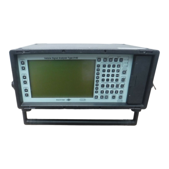
About the Type 2145 About the Type 2145 The Analyzer The Order Tracking Analyzer Type 2145 is a portable, digital- filter, frequency analyzer which can also perform order analyses for acoustics and vibration measurements. Its light weight and water-repellent cabinet make it especially well-suited for use in the field. -
Page 11: About This User Guide
Purpose of Manual This manual introduces you to the operating principles of the Type 2145 and gives you an overview of the analyzer’s possibil- ities. Examples of measurement procedures and data processing are also given. You will find that the analyzer is very easy to use once you have become familiar with its working principles. - Page 12 Chapter 14 is about service and repair. Interface Use of the interfaces (serial and parallel) is described in Vol. 2: Interface along with information on data formats used by the analyzer. 1 – 4 Order Tracking Analyzer Type 2145 Brüel & Kjær User Manual Vol.1...
-
Page 13: Installation And Maintenance
Use of a Car Battery for External DC Supply ....2 – 5 Grounding Considerations ..........2 – 6 Cleaning the Disk Drive ............ 2 – 8 Installing the Software Key ..........2 – 9 2 – 1 BB 0877 – 14 Order Tracking Analyzer Type 2145 User Manual Vol.1... -
Page 14: Power Supply
Replace the cover and insert the battery box into the ana- lyzer. Secure the battery box by turning the release screw. Label the battery box with the type of batteries contained. 2 – 2 Order Tracking Analyzer Type 2145 Brüel & Kjær User Manual Vol.1... -
Page 15: Mains Supply
To power the analyzer from the mains supply, Power Supply ZG 0342 (included as accessory) can be connected to the Exter- nal Power 7-pin DIN plug on the rear panel via Cable AQ 0035. 2 – 3 BB 0877 – 14 Order Tracking Analyzer Type 2145 User Manual Vol.1... -
Page 16: Recharging The Batteries
10 – 40°C. Likewise, NiCd batteries may exhibit a “memory effect” if used incorrectly. This effect leads to a decreased operating time, but can be avoided by letting 2 – 4 Order Tracking Analyzer Type 2145 Brüel & Kjær User Manual Vol.1... -
Page 17: Use Of A Car Battery For External Dc Supply
However, if other instruments are used with the analyzer, ensure that they are also properly isolated, otherwise they can short-circuit the car battery. 2 – 5 BB 0877 – 14 Order Tracking Analyzer Type 2145 User Manual Vol.1... -
Page 18: Grounding Considerations
Switch all instruments “Off ” before making any changes to ground connections. 2 – 6 Order Tracking Analyzer Type 2145 Brüel & Kjær User Manual Vol.1... - Page 19 On all instruments which have a ground connection in their mains supply connector, connect the chassis to mains 2 – 7 BB 0877 – 14 Order Tracking Analyzer Type 2145 User Manual Vol.1...
-
Page 20: Cleaning The Disk Drive
Press “F6” (Memory) on page 2 of the MAIN MENU. Set the Select Memory field to Disk using “F1”. Press “F7” (File List). Press “F8” (Page 1) to return page 1 (step 4). 2 – 8 Order Tracking Analyzer Type 2145 Brüel & Kjær User Manual Vol.1... -
Page 21: Installing The Software Key
Repeat steps 5 and 6 as required to give a total cleaning time of approximately 30 s. Installing the Software Key To run any optional application program on the Type 2145, the software key provided with the application program must be 912994e Fig. - Page 22 Unscrew the eight short screws at the top of the front and rear panels. Unscrew the four long screws at the bottom. Disconnect the three flat cables from circuit board 8. Remove circuit board 9 (ZD 0712). 2 – 10 Order Tracking Analyzer Type 2145 Brüel & Kjær User Manual Vol.1...
- Page 23 Fig. 2.5. Any free socket may be used. Re-insert the circuit board, reconnect the flat cables and reassemble the analyzer. 2 – 11 BB 0877 – 14 Order Tracking Analyzer Type 2145 User Manual Vol.1...
- Page 24 2 – 12 Order Tracking Analyzer Type 2145 Brüel & Kjær User Manual Vol.1...
-
Page 25: Controls And Connections
Chapter 3 Controls and Connections Front Panel ................3 – 2 Rear Panel ................3 – 5 3 – 1 BB 0877 – 14 Order Tracking Analyzer Type 2145 User Manual Vol.1... -
Page 26: Front Panel
Chapter 3 – Controls and Connections Front Panel Front Panel Fig. 3.1 Front Panel of the Order Tracking Analyzer Type 2145 Screen Keys Viewing Angle “ ”: The analyzer’s display contrast can be adapted to different vertical viewing angles using these keys. - Page 27 “Start”: Clears all input buffers and starts a measurement if the analyzer is in Measurement Mode. “Proceed”: Continues an interrupted measurement without clearing the buffers. 3 – 3 BB 0877 – 14 Order Tracking Analyzer Type 2145 User Manual Vol.1...
- Page 28 Upper/ Lower Indicator (see section 10.1). Reset Key “Reset”: Resets the software in the analyzer back to its starting point. Power Key “Power On/Off”: Switches the analyzer on or off. 3 – 4 Order Tracking Analyzer Type 2145 Brüel & Kjær User Manual Vol.1...
-
Page 29: Rear Panel
Note: If this key is pressed while the disk drive is active, the analyzer waits until the drive has stopped before switching off. Rear Panel Fig. 3.2 Rear panel of the Order Tracking Analyzer Type 2145 Polarization Voltage Selects a microphone polarization voltage of 0, 28, or 200 V for each input as given on the microphone calibration chart. - Page 30 The input voltage range for these is 0 to + 6.4 V which the analyzer samples at 10 Hz. See under “DC Channel Input Characteristics” in the specifications for full de- tails. 3 – 6 Order Tracking Analyzer Type 2145 Brüel & Kjær User Manual Vol.1...
- Page 31 (under Serial Receive Synchronisation [SRS] control, see below). Three external signals are used to control the flow of 3 – 7 BB 0877 – 14 Order Tracking Analyzer Type 2145 User Manual Vol.1...
- Page 32 Must be stable for 200 n s before and after the clock pulse goes high. Pin 14 Serial Receive Synchronisation (SRS). Each falling edge of this synchronisation signal freezes a copy 3 – 8 Order Tracking Analyzer Type 2145 Brüel & Kjær User Manual Vol.1...
- Page 33 BNC sockets for powering transducers, e.g. the Photoelectric Probe MM 0024. See under “Main and Auxiliary Tacho Inputs” in Chapter 13. 3 – 9 BB 0877 – 14 Order Tracking Analyzer Type 2145 User Manual Vol.1...
- Page 34 Note: There is a risk of damage to these Tacho Inputs if the applied tacho signals are outside the range of ± % 20 V peak. Auxiliary Connector I Not used on the 2145. Auxiliary Connector II For the output of detected trigger pulses; otherwise, reserved for future options.
- Page 35 WARNING! Switch off all equipment before connecting or dis- connecting their digital interfaces. Failure to do so can damage the equipment. Remote Control Sound Source Not used on the 2145. Remote Control Mic. Boom Not used on the 2145. Preamplifier 7-pin connector(s) for Brüel &...
- Page 36 Fig. 3.3. The socket is also used when recharging NiCd batteries. Alternatively, the ZG 0342 can be plugged into the 2145 instead of Battery Box ZG 0146. When using an external 3 – 12 Order Tracking Analyzer Type 2145 Brüel &...
- Page 37 Chassis/ Floating WARNING: Connects/disconnects analogue ground to/from the chassis (rear panel) of the 2145. See section 2.2 for further information on grounding considerations. 3 – 13 BB 0877 – 14 Order Tracking Analyzer Type 2145 User Manual Vol.1...
- Page 38 3 – 14 Order Tracking Analyzer Type 2145 Brüel & Kjær User Manual Vol.1...
-
Page 39: Getting Started
Changing Parameters in a Set-up ......4 – 10 Changing Operating Parameters in a Sub-menu ..4 – 10 Changing Numerical Parameters in a Sub-menu ..4 – 11 4 – 1 BB 0877 – 14 Order Tracking Analyzer Type 2145 User Manual Vol.1... -
Page 40: Switching On
Select a program disk. Insert the program disk in the disk drive. Make a Master Reset (see section 3.2). 4 – 2 Order Tracking Analyzer Type 2145 Brüel & Kjær User Manual Vol.1... -
Page 41: Loading Via The Ieee Interface
If you have an IBM PC XT, AT, PS/2 or one that is 100% com- patible fitted with a GPIB interface card, it is possible to boot the analyzer from the PC. Details are given in Volume 2. 4 – 3 BB 0877 – 14 Order Tracking Analyzer Type 2145 User Manual Vol.1... -
Page 42: General Measurement Procedure
The way to change these settings is described in the following sections. What they mean and how to use them is described in chapters 5 to 7. 4 – 4 Order Tracking Analyzer Type 2145 Brüel & Kjær User Manual Vol.1... -
Page 43: The Menu And Help
MAIN MENU and their use. Page 1 Current Set-up Gives you an overview of the settings currently activated. 4 – 5 BB 0877 – 14 Order Tracking Analyzer Type 2145 User Manual Vol.1... - Page 44 512 s. The conditions controlling interval averaging, i.e. slope, tacho-parameter, upper and lower limits can be set using this menu as well as the autorange time. 4 – 6 Order Tracking Analyzer Type 2145 Brüel & Kjær User Manual Vol.1...
- Page 45 This can be used to display a list of files in the data memory or on the disk, format new disks, delete or rename files and transfer files between data memory and disk. 4 – 7 BB 0877 – 14 Order Tracking Analyzer Type 2145 User Manual Vol.1...
-
Page 46: Efficient Use Of The Menus
Pass-by Noise Measurement System Type 3558. 4.3.4 Efficient Use of the Menus Two other useful keys in Set-up Mode are “Next Menu” and “Prev. Page”. 4 – 8 Order Tracking Analyzer Type 2145 Brüel & Kjær User Manual Vol.1... - Page 47 Measurement Mode when setting up interactive parameters such as screen displays. Note, however, that it cannot be used to switch between the various displays of the Measurement Mode. 4 – 9 BB 0877 – 14 Order Tracking Analyzer Type 2145 User Manual Vol.1...
-
Page 48: Changing Parameters In A Set-Up
In certain cases, e.g. when moving the 4 – 10 Order Tracking Analyzer Type 2145 Brüel & Kjær User Manual Vol.1... -
Page 49: Changing Numerical Parameters In A Sub-Menu
If the entered parameter value is illegal, the echo field flashes and the numerical parameter is set to the nearest legal value: Max. Input (PWR) : 138 dB 4 – 11 BB 0877 – 14 Order Tracking Analyzer Type 2145 User Manual Vol.1... - Page 50 In this case, the rest of the set-up must be checked. 4 – 12 Order Tracking Analyzer Type 2145 Brüel & Kjær User Manual Vol.1...
-
Page 51: Main Menu
Common to All Tacho Parameters – Page 1....5 – 23 Setting up Rotation V1 (Order Tracking Source) – Page 2 ........5 – 26 Setting up Rotation P2,V2,A2 – Page 3......5 – 28 5 – 1 BB 0877 – 14 Order Tracking Analyzer Type 2145 User Manual Vol.1... - Page 52 ................5 – 33 Quantities affected/not affected by Averaging....5 – 34 Interval Averaging ............. 5 – 35 Interval Averaging combined with a Normal Multispectrum ........5 – 37 5 – 2 Order Tracking Analyzer Type 2145 Brüel & Kjær User Manual Vol.1...
-
Page 53: Introduction
For convenience, the soft keys “F1” to “F8” by the right-hand side of the screen will be shown throughout this manual. Fig. 5.1 The eight items displayed on page 1 of the MAIN MENU 5 – 3 BB 0877 – 14 Order Tracking Analyzer Type 2145 User Manual Vol.1... -
Page 54: Analysis Set-Up
Fig. 5.2. The left half of Fig. 5.2 also shows a summary of the current analysis set-up. Fig. 5.2 Page 1 of the sub-menu for Analysis Set-up. Autospectra and/or orders, number of channels and filter bandwidth 5 – 4 Order Tracking Analyzer Type 2145 Brüel & Kjær User Manual Vol.1... - Page 55 Note that Order Resolution is not directly user definable but a consequence of the selections made via “F2” and “F4”. 5 – 5 BB 0877 – 14 Order Tracking Analyzer Type 2145 User Manual Vol.1...
- Page 56 For guidance refer to the avail- able on-screen help. Note the usefulness of using “F5” and “F6” for quickly entering equidistant orders, i.e. whatever 5 – 6 Order Tracking Analyzer Type 2145 Brüel & Kjær User Manual Vol.1...
- Page 57 Manually, to improve real-time performance. b. Automatically, if its value is not within (Min, Max). See section 8.3.3 for more information on individually set- up orders. 5 – 7 BB 0877 – 14 Order Tracking Analyzer Type 2145 User Manual Vol.1...
-
Page 58: Input
“F1”), page 1 invites you to enter which type of input you are using (via “F2”), which high-pass filter you want to use or A-weighting (via “F3”), the maximum expected value of the input 5 – 8 Order Tracking Analyzer Type 2145 Brüel & Kjær User Manual Vol.1... -
Page 59: Calibration
To calibrate the analyzer for vibration measurements, a reference vibration must be applied to the accelerometer used. The Cali- bration Exciter Type 4294 will provide a reference vibration level. See section 5.4.3. 5 – 9 BB 0877 – 14 Order Tracking Analyzer Type 2145 User Manual Vol.1... -
Page 60: Calibration For Sound Measurements
With page 2 of the sub-menu CALIBRATION on display (see Fig. 5.7), use “F1” to select the preamplifier channel (A or B) you are using. Enter the Calib. Level for the piston- 5 – 10 Order Tracking Analyzer Type 2145 Brüel & Kjær User Manual Vol.1... - Page 61 Place the pistonphone/calibrator over the microphone and switch it on. Select a convenient time via “F6” for averaging 5 – 11 BB 0877 – 14 Order Tracking Analyzer Type 2145 User Manual Vol.1...
- Page 62 2 on display, press either the Auto Range pushkey or the Max Input pushkey (for the channel you are using). After this repeat the calibration procedure. 5 – 12 Order Tracking Analyzer Type 2145 Brüel & Kjær User Manual Vol.1...
-
Page 63: Calibration For Ac Signal Voltages (Direct Input)
You are invited to enter the value for the User Reference. In this example the User Reference will be set to the value of 1.0E-06 Unit (representing 5 – 13 BB 0877 – 14 Order Tracking Analyzer Type 2145 User Manual Vol.1... - Page 64 Calib. Frequency, e.g. 1.00 kHz. Enter the sensitivity of the transducer (in terms of volts per Unit) field example Transducer Sens. 31.62 mV/Unit. 5 – 14 Order Tracking Analyzer Type 2145 Brüel & Kjær User Manual Vol.1...
- Page 65 PROTECT will appear at the bottom of the screen. Check the value you 5 – 15 BB 0877 – 14 Order Tracking Analyzer Type 2145 User Manual Vol.1...
-
Page 66: Calibration For Vibration Measurements
With page 1 of the sub-menu CALIBRATION on display (see Fig. 5.10), use “F1” to select the channel (A or B) you are using. invited enter value 5 – 16 Order Tracking Analyzer Type 2145 Brüel & Kjær User Manual Vol.1... - Page 67 Calib. Frequency enter 160 Hz. Enter the accelerometer sensitivity in the field for Transducer Sens. For a Brüel & Kjær Accelerometer Type 4382, a typical entry will be 3.16 pC/ ms 5 – 17 BB 0877 – 14 Order Tracking Analyzer Type 2145 User Manual Vol.1...
- Page 68 Check the value you entered in step 2 for Max. Input (PWR) and while you are there switch, if necessary, the Input Protect to OFF via “F6”. Alter- 5 – 18 Order Tracking Analyzer Type 2145 Brüel & Kjær User Manual Vol.1...
-
Page 69: Tacho Input And Tacho Parameters
V1 from the rest. Important! If you want the analyzer to perform order analysis or angular gating, then you must set up and activate V1. 5 – 19 BB 0877 – 14 Order Tracking Analyzer Type 2145 User Manual Vol.1... -
Page 70: Tacho Input
(see also section 8.6.1 under “Important”). In the example considered here this will be 96. If the ana- lyzer is receiving the tacho signals, the left of the screen 5 – 20 Order Tracking Analyzer Type 2145 Brüel & Kjær User Manual Vol.1... - Page 71 The Hold Off percentage can be set to any value from 0 to 90%. This feature helps to reject spurious pulses in the tacho signal, 5 – 21 BB 0877 – 14 Order Tracking Analyzer Type 2145 User Manual Vol.1...
- Page 72 90 % Hold off Missing pulse Neglected pulse 932783e Fig. 5.13 How Hold off Percentages greater 50% can cause the analyzer to lock onto half the tacho signal frequency 5 – 22 Order Tracking Analyzer Type 2145 Brüel & Kjær User Manual Vol.1...
-
Page 73: Setting Up Tacho Parameters
To make it clear, the example in section 5.5.1 will be considered. We will assume that an engine speed of 2500 rpm moves the car at 100 km/h. 5 – 23 BB 0877 – 14 Order Tracking Analyzer Type 2145 User Manual Vol.1... -
Page 74: Common To All Tacho Parameters
Fig. 5.14 Page 1 of the sub-menu Tacho Parameters With page 1 of the sub-menu TACHO PARAMETERS on display, make sure that you have selected the Tacho Source (MAIN 5 – 24 Order Tracking Analyzer Type 2145 Brüel & Kjær User Manual Vol.1... - Page 75 “F5” to display page 2 (Rotation Set-up V1). “F6” to display page 3 (Rotation Set-up P2,V2,A2). “F7” to display page 4 (Position Set-up P2,V2,A2). “F8” to display page 5 (User Set-up P2,V2,A2). 5 – 25 BB 0877 – 14 Order Tracking Analyzer Type 2145 User Manual Vol.1...
-
Page 76: Setting Up Rotation V1 (Order Tracking Source)
FACTOR, see the available on-screen help to tell you how to do this. If there is no gearing, both FRACTION or FACTOR will be 1. If, however, the FACTOR is unknown, 5 – 26 Order Tracking Analyzer Type 2145 Brüel & Kjær User Manual Vol.1... - Page 77 “F5” and when the engine or machine is running, the true speed V1 will be displayed on the left of the screen. You are now finished with this page. 5 – 27 BB 0877 – 14 Order Tracking Analyzer Type 2145 User Manual Vol.1...
-
Page 78: Setting Up Rotation P2,V2,A2
FACTOR, see the available on-screen help to tell you how to do this. If there is no gearing, both FRACTION or FACTOR will be 1. If, however, the FACTOR is unknown, 5 – 28 Order Tracking Analyzer Type 2145 Brüel & Kjær User Manual Vol.1... - Page 79 “F5” and when the engine or machine is running, the true speed V2 will be displayed on the left of the screen. You are now finished with this page. 5 – 29 BB 0877 – 14 Order Tracking Analyzer Type 2145 User Manual Vol.1...
-
Page 80: Setting Up Position P2,V2,A2
Choose (via “F2”) the units in which you want to measure V2 (representing velocity or speed). You have a choice be- tween M(etres)/S(econd), K(ilo)M(etres)/H(our), F(eet) P(er) M(inute) or M(iles) P(er) H(our). 5 – 30 Order Tracking Analyzer Type 2145 Brüel & Kjær User Manual Vol.1... - Page 81 You also need to know the true (constant) speed of the vehicle under test. If, for practical reasons, the vehicle cannot be driven at a constant speed, 5 – 31 BB 0877 – 14 Order Tracking Analyzer Type 2145 User Manual Vol.1...
-
Page 82: Setting Up User P2,V2,A2
To the analyzer, it is known as User and symbolised by U. With this set-up then, you get U, U per second (U/S) and U per second per second (U/S 5 – 32 Order Tracking Analyzer Type 2145 Brüel & Kjær User Manual Vol.1... -
Page 83: Averaging
Range Time. The Auto Range Time is the time used by the analyzer’s input attenuators for each step towards optimum ad- justment to the incoming signals. 5 – 33 BB 0877 – 14 Order Tracking Analyzer Type 2145 User Manual Vol.1... -
Page 84: Quantities Affected/Not Affected By Averaging
0.9766 ms. 5.7.1 Quantities affected/not affected by Averaging The selected averaging mode and time are applied to the follow- ing quantities: Autospectra 5 – 34 Order Tracking Analyzer Type 2145 Brüel & Kjær User Manual Vol.1... -
Page 85: Interval Averaging
Averaging stops immediately if the tacho parameter moves out of this in- terval, and will proceed again depending on how it re-enters this 5 – 35 BB 0877 – 14 Order Tracking Analyzer Type 2145 User Manual Vol.1... - Page 86 Fig. 5.19. Read also the available on-screen help. Fig. 5.19 Page 2 of the sub-menu Averaging Use “F1” to activate or de-activate Interval Averaging, i.e. select accordingly either ON or OFF. 5 – 36 Order Tracking Analyzer Type 2145 Brüel & Kjær User Manual Vol.1...
-
Page 87: Interval Averaging Combined With A Normal Multispectrum
Exponential Averaging The time taken between individual spectra in a normal multi- spectrum is not influenced by the tacho parameter, however if 5 – 37 BB 0877 – 14 Order Tracking Analyzer Type 2145 User Manual Vol.1... - Page 88 The effective averaging time is the sum of T etc. averaging is stopped for longer periods, this could possibly lead to lower confidence in the measurements. 5 – 38 Order Tracking Analyzer Type 2145 Brüel & Kjær User Manual Vol.1...
-
Page 89: Main Menu
Gated Multispectrum – Page 4 of 7 ........ 6 – 22 Internal Trigger – Page 5 of 7......... 6 – 26 External Trigger – Page 6 of 7........6 – 29 6 – 1 BB 0877 – 14 Order Tracking Analyzer Type 2145 User Manual Vol.1... - Page 90 Memory (File List) – Page 2 of 3........6 – 40 Memory (Data Transfer) – Page 3 of 3 ......6 – 41 I/O Interface ................6 – 43 6 – 2 Order Tracking Analyzer Type 2145 Brüel & Kjær User Manual Vol.1...
-
Page 91: Introduction
Organise data in memory and on disk. The item I/O Interface is described in Volume 2. Fig. 6.1 The seven items displayed on page 2 of the MAIN MENU 6 – 3 BB 0877 – 14 Order Tracking Analyzer Type 2145 User Manual Vol.1... -
Page 92: Display Modes
With page 2 of the MAIN MENU (Fig. 6.1) on display, press soft key “F1” to display page 1 of the sub-menu Display Modes shown in Fig. 6.2. The left half of Fig. 6.2 shows diagrammatically 6 – 4 Order Tracking Analyzer Type 2145 Brüel & Kjær User Manual Vol.1... - Page 93 Unit IMPERIAL Charge dB (decibels) METRIC g (gravitational) IMPERIAL Enter via “F3” the centre frequency for the highest band of the autospectrum to be displayed. 6 – 5 BB 0877 – 14 Order Tracking Analyzer Type 2145 User Manual Vol.1...
-
Page 94: Spectra And Orders Display
Check your entry with the corresponding diagram on the left. Select via “F3” a value for the displayed range. Check your selection with the corresponding diagram on the left. 6 – 6 Order Tracking Analyzer Type 2145 Brüel & Kjær User Manual Vol.1... -
Page 95: Tacho Parameters Display - Page 3 Of 3
14. With page 3 of the DISPLAY MODES sub-menu on display, decide (via “F1”) which display UPPER (and SINGLE) or LOW- ER you want to set up. The left half of Fig. 6.4 shows dia- 6 – 7 BB 0877 – 14 Order Tracking Analyzer Type 2145 User Manual Vol.1... -
Page 96: Text
Text Application This item is for creating user texts for labelling files created by the analyzer in connection with autosequences, set-ups, frequen- cy weightings and measurements. 6 – 8 Order Tracking Analyzer Type 2145 Brüel & Kjær User Manual Vol.1... - Page 97 The display shown in Fig. 6.5 is for creating text files, copying them to other specified files, e.g. to label existing measurement files, and copying them automatically to the files of future meas- 6 – 9 BB 0877 – 14 Order Tracking Analyzer Type 2145 User Manual Vol.1...
- Page 98 Key in a new TEXT file number and press “F5” to create this file. The new TEXT file will then appear listed on the left. 6 – 10 Order Tracking Analyzer Type 2145 Brüel & Kjær User Manual Vol.1...
-
Page 99: Edit Text - Page 2 Of 2
The text between the square brackets [] applies to the text line previ- ously highlighted on page 1 (Fig. 6.5). 6 – 11 BB 0877 – 14 Order Tracking Analyzer Type 2145 User Manual Vol.1... -
Page 100: Hold
The result will be the maximum or minimum level registered in each frequen- cy- and broad-band (A/L and W) channel. 6 – 12 Order Tracking Analyzer Type 2145 Brüel & Kjær User Manual Vol.1... - Page 101 Select via “F2” whether you want to hold on MINimum or MAXimum conditions. Select via “F3” which Mode of spectrum hold you require, the options are: means no hold required. INACTIVE 6 – 13 BB 0877 – 14 Order Tracking Analyzer Type 2145 User Manual Vol.1...
- Page 102 However, you should avoid applying them to linearly averaged data since this can lead to comparisons between data of unequal confidence. 6 – 14 Order Tracking Analyzer Type 2145 Brüel & Kjær User Manual Vol.1...
-
Page 103: Trigger Multimode
With page 2 of the MAIN MENU (Fig. 6.1) on display, press soft key “F4” to display page 1 of the sub-menu Trigger Multimode shown in Fig. 6.8. 6 – 15 BB 0877 – 14 Order Tracking Analyzer Type 2145 User Manual Vol.1... - Page 104 EXTERNAL Set-up on page 6, see section 6.5.6. Set-up on page 7, see section 6.5.7. TIME For manual triggering via the front panel, see MANUAL section 6.5.8. 6 – 16 Order Tracking Analyzer Type 2145 Brüel & Kjær User Manual Vol.1...
-
Page 105: Interval Multispectrum - Page 2 Of 7
Key in via “F4” and “F5” values for the Upper and Lower Limits of interest for the selected Tacho Parameter. 6 – 17 BB 0877 – 14 Order Tracking Analyzer Type 2145 User Manual Vol.1... - Page 106 (run-up, run-up&run-down) or the top (run-down). † Records for that part of the range of interest skipped by the tacho parameter will be left empty as dummies. 6 – 18 Order Tracking Analyzer Type 2145 Brüel & Kjær User Manual Vol.1...
- Page 107 This approach has two distinct advantages: The averaging time is automatically adjusted by the control- ling tacho parameter and data acquisition is truly real-time. 6 – 19 BB 0877 – 14 Order Tracking Analyzer Type 2145 User Manual Vol.1...
-
Page 108: Normal Multispectrum - Page 3 Of 7
(Fig. 6.8), press soft key “F4” to get page 3 as shown in Fig. 6.10. Fig. 6.10 Page 3 of the sub-menu Trigger Multimode for setting up the conditions for generating a Normal Multispectrum 6 – 20 Order Tracking Analyzer Type 2145 Brüel & Kjær User Manual Vol.1... - Page 109 Multispectrum are interlocked. In certain cases, therefore, the analyzer will not allow you to enter the parameter value of your choice. If this happens, check the rest of the analyzer set-up. 6 – 21 BB 0877 – 14 Order Tracking Analyzer Type 2145 User Manual Vol.1...
-
Page 110: Gated Multispectrum - Page 4 Of 7
Gated Multispectrum will now contain data which is the average for the two data collections. Hence, when the analyzer is triggered N times, the Gated Multispectrum will 6 – 22 Order Tracking Analyzer Type 2145 Brüel & Kjær User Manual Vol.1... - Page 111 Fig. 6.11 The controlling parameters used in the set-up for collecting a Normal Multispectrum Trigger Trigger Delay (positive only) Gating Width Data Collection 900204/2e Fig. 6.12 A measurement cycle in the collection of a gated multispectrum 6 – 23 BB 0877 – 14 Order Tracking Analyzer Type 2145 User Manual Vol.1...
- Page 112 Lin. Avg. : Gating Width Exp. Avg.: Averaging continues until measurement is stopped manually. 891852/1e Fig. 6.13 Parameters selectable in the collection of a gated multispec- trum 6 – 24 Order Tracking Analyzer Type 2145 Brüel & Kjær User Manual Vol.1...
- Page 113 Note: the narrower the selected bandwidth, the smaller will be the allowable Number of Spectra per Trigger, see Table 6.1. 6 – 25 BB 0877 – 14 Order Tracking Analyzer Type 2145 User Manual Vol.1...
-
Page 114: Internal Trigger - Page 5 Of 7
The analyzer can be triggered whenever the level of a chosen measurement parameter either exceeds or falls below a given pre-set value. For example, whenever the level measured in the 6 – 26 Order Tracking Analyzer Type 2145 Brüel & Kjær User Manual Vol.1... - Page 115 Do this as described in steps 3 and 4 in the fol- lowing. 6 – 27 BB 0877 – 14 Order Tracking Analyzer Type 2145 User Manual Vol.1...
- Page 116 BAND-PASS Means in the channel whose Band-pass Fil- ter Centre Frequency is selected via “F6”/ “F7”. Means in the channel whose Order is selected ORDER via “F6”/“F7”. 6 – 28 Order Tracking Analyzer Type 2145 Brüel & Kjær User Manual Vol.1...
-
Page 117: External Trigger - Page 6 Of 7
(Fig. 6.8), press “F7” to get page 6 as shown in Fig. 6.16. Fig. 6.16 Page 6 of the sub-menu Trigger Multimode for setting up the conditions for an External Trigger 6 – 29 BB 0877 – 14 Order Tracking Analyzer Type 2145 User Manual Vol.1... -
Page 118: Time Trigger - Page 7 Of 7
Key in values for the Hour, Minute and Second via “F2”, “F3” and “F4” respectively. The maximum allowable entries for a 12 and 24 hour clock are respectively 12:59:59 and 23:59:59. 6 – 30 Order Tracking Analyzer Type 2145 Brüel & Kjær User Manual Vol.1... -
Page 119: Manual Trigger
Fig. 6.8 on display via “F2”. Note: triggering will take place only in the measurement mode and only after the Averaging Control “Start” push key has been pressed. 6 – 31 BB 0877 – 14 Order Tracking Analyzer Type 2145 User Manual Vol.1... -
Page 120: Spectrum Weighting
The left side of Fig. 6.18 shows the selected frequency weighting as a plot of decibels against frequency (the dashed line). The vertical line is a cursor. The steps in the frequency scale match 6 – 32 Order Tracking Analyzer Type 2145 Brüel & Kjær User Manual Vol.1... - Page 121 Linear, i.e. zero at all frequencies. U1 and U2 User-defined weightings, see section 6.6.2. Standard A - weighting. Standard B - weighting. Standard C - weighting. Standard D - weighting. 6 – 33 BB 0877 – 14 Order Tracking Analyzer Type 2145 User Manual Vol.1...
- Page 122 – 30 – 40 – 50 – 60 – 70 Frequency (Hz) 900173e Fig. 6.19 Curves for the standard A, B, C and D frequency weightings 6 – 34 Order Tracking Analyzer Type 2145 Brüel & Kjær User Manual Vol.1...
-
Page 123: Defining Frequency Weighting - Page 2 Of 2
The vertical line is a cursor. The steps in the frequency scale match the filter bandwidth selected on page 1 of the sub- menu Analysis Set-up, see section 5.2. 6 – 35 BB 0877 – 14 Order Tracking Analyzer Type 2145 User Manual Vol.1... - Page 124 Standard D - weighting. Once on display, you can edit it as described above and save it as a user-defined frequency weighting as described in step 6 – 36 Order Tracking Analyzer Type 2145 Brüel & Kjær User Manual Vol.1...
-
Page 125: Memory
“F6” to display page 1 of the sub-menu Memory shown in Fig. 6.21. The sub-menu shown in Fig. 6.21 is for selecting analyzer or disk memory, sorting files, disk formatting and bulk erasure. 6 – 37 BB 0877 – 14 Order Tracking Analyzer Type 2145 User Manual Vol.1... - Page 126 Files containing only user defined text, see sec- TEXT tion 6.3. Files containing a user-defined sequence of au- AUTOSEQ tomatic operations, see section 7.3. 6 – 38 Order Tracking Analyzer Type 2145 Brüel & Kjær User Manual Vol.1...
- Page 127 “F2”. If you are dealing with disk memory, pressing “F6” will delete all files. You must confirm your decision via “F5” within 5 seconds while the message CONFIRM flashes. 6 – 39 BB 0877 – 14 Order Tracking Analyzer Type 2145 User Manual Vol.1...
- Page 128 (i.e. renumbering) files. The NAME of a file is its number which can be anything from 001 to 999 (user-defined frequency weighting files have NAMEs 6 – 40 Order Tracking Analyzer Type 2145 Brüel & Kjær User Manual Vol.1...
- Page 129 “F1” the direction of data transfer, see step 1 in section 6.7.1. When you have made your choice, press soft key “F8” to get 6 – 41 BB 0877 – 14 Order Tracking Analyzer Type 2145 User Manual Vol.1...
- Page 130 Press “F4” to start the data transfer. Error messages will appear if data transfer is not straightforward or possible. Press “F5”/“F6” to highlight the first/last file listed. 6 – 42 Order Tracking Analyzer Type 2145 Brüel & Kjær User Manual Vol.1...
-
Page 131: I/O Interface
Volume 2 which is the manual for analyzer’s interfaces. Accompanying on-screen help is still available by pressing “Main Menu” then “F1”. 6 – 43 BB 0877 – 14 Order Tracking Analyzer Type 2145 User Manual Vol.1... - Page 132 6 – 44 Order Tracking Analyzer Type 2145 Brüel & Kjær User Manual Vol.1...
-
Page 133: Main Menu
Set Wake-up – Page 1 of 2 ..........7 – 14 Set Clock – Page 2 of 2 ............ 7 – 16 Back Lighting ............... 7 – 17 Applications ................7 – 19 7 – 1 BB 0877 – 14 Order Tracking Analyzer Type 2145 User Manual Vol.1... -
Page 134: Introduction
Fig. 7.1 The five items displayed on page 3 of the MAIN MENU Preselected Set-up Application This item is for installing whole or parts of a preselected set-up from the analyzer’s memory. The files containing set-up infor- 7 – 2 Order Tracking Analyzer Type 2145 Brüel & Kjær User Manual Vol.1... - Page 135 You can inspect the set-up of the Fig. 7.2 Page 1 of the sub-menu Preselected Set-up for installing whole or parts of a preselected set-up from the analyzer’s memory 7 – 3 BB 0877 – 14 Order Tracking Analyzer Type 2145 User Manual Vol.1...
-
Page 136: Autosequence
The analyzer will also remember the set-up existing at the time of learning an autosequence and can be made to use this when performing the autosequence. Alternatively, the set-up current 7 – 4 Order Tracking Analyzer Type 2145 Brüel & Kjær User Manual Vol.1... - Page 137 The execution of an autosequence can be initiated either by pressing Autosequence “Stop/Step” or from page 3 of this sub- menu. An autosequence can be halted manually via Autosequence “Stop/Step”. 7 – 5 BB 0877 – 14 Order Tracking Analyzer Type 2145 User Manual Vol.1...
-
Page 138: Autosequence - Page 1 Of 3
Activate the set-up (does not apply to the cal- bration part) which existed at the time of pro- 7 – 6 Order Tracking Analyzer Type 2145 Brüel & Kjær User Manual Vol.1... - Page 139 You can start from either Fig. 7.4 or Fig. 7.5. In Fig. 7.4 the soft keys “F1” and “F2” have no function. 7 – 7 BB 0877 – 14 Order Tracking Analyzer Type 2145 User Manual Vol.1...
- Page 140 Autosequence Fig. 7.4 Page 2 of the sub-menu Autosequence listing no existing autose- quences Fig. 7.5 Page 2 of the sub-menu Autosequence listing existing autose- quences 7 – 8 Order Tracking Analyzer Type 2145 Brüel & Kjær User Manual Vol.1...
- Page 141 (Fig. 7.6 on display) If you have finished and you want to file the autosequence you have just programmed, select OFF via “F3” (the LED switches off). Then key in a file number 7 – 9 BB 0877 – 14 Order Tracking Analyzer Type 2145 User Manual Vol.1...
- Page 142 Automatic learn stop: This occurs when all 200 steps have been used or when one of the soft pushkeys “F1” to “F6” on page 3 has been pushed. 7 – 10 Order Tracking Analyzer Type 2145 Brüel & Kjær User Manual Vol.1...
- Page 143 (you may have to do this twice to be certain). Now manually add this last step then go to step 6. 7 – 11 BB 0877 – 14 Order Tracking Analyzer Type 2145 User Manual Vol.1...
-
Page 144: Executing An Autosequence
“F7” then initiate the execution of the autosequence. Re- member that the “F7” entry applies to all listed autose- quences. 7 – 12 Order Tracking Analyzer Type 2145 Brüel & Kjær User Manual Vol.1... -
Page 145: Real-Time Clock
“wake-up” the analyzer from its stand-by mode and, if required, make it execute the current Autosequence (see section 7.3). 7 – 13 BB 0877 – 14 Order Tracking Analyzer Type 2145 User Manual Vol.1... -
Page 146: Set Wake-Up - Page 1 Of 2
The left side of Fig. 7.8 shows the current Actual Clock Status and Actual Wake-up Status. The Actual Clock Status, which advances automatically by one-second intervals, shows the current settings for the Date 7 – 14 Order Tracking Analyzer Type 2145 Brüel & Kjær User Manual Vol.1... - Page 147 When it wakes up at the preset time, it goes through its usual power on test and, if set up accordingly, executes the Autosequence pointed out by the cursor on page 7 – 15 BB 0877 – 14 Order Tracking Analyzer Type 2145 User Manual Vol.1...
-
Page 148: Set Clock - Page 2 Of 2
Key in the current hour (1 to 12 for AM/PM, and 1 to 24 for 24h) and press “F5”. Key in the current minute (0 to 59) and press “F6”. 7 – 16 Order Tracking Analyzer Type 2145 Brüel & Kjær User Manual Vol.1... -
Page 149: Back Lighting
“F1” here or via the toggle switch marked Display Backlighting On/Off on the rear panel. The purpose of back lighting control is to conserve battery power. 7 – 17 BB 0877 – 14 Order Tracking Analyzer Type 2145 User Manual Vol.1... - Page 150 Back lighting switches on with any key push ECONOMIC and stays on for a specified period after the last key push. The specified period is entered via “F4”. 7 – 18 Order Tracking Analyzer Type 2145 Brüel & Kjær User Manual Vol.1...
-
Page 151: Applications
3 in section 9.3.3). In con- nection with the type 3558 software, the analyzer provides on- screen help for the part concerning itself. 7 – 19 BB 0877 – 14 Order Tracking Analyzer Type 2145 User Manual Vol.1... - Page 152 7 – 20 Order Tracking Analyzer Type 2145 Brüel & Kjær User Manual Vol.1...
-
Page 153: Analysis Functions
The W-band..............8 – 10 Choosing an Analogue Input Filter ......8 – 11 High-pass Filters ............. 8 – 11 A-weighting Filter ............8 – 12 8 – 1 BB 0877 – 14 Order Tracking Analyzer Type 2145 User Manual Vol.1... - Page 154 DC Channels ................. 8 – 17 Digital Channel ..............8 – 17 Overload Indicators ............8 – 18 8.10 Summary of Analysis Functions ......... 8 – 20 8 – 2 Order Tracking Analyzer Type 2145 Brüel & Kjær User Manual Vol.1...
-
Page 155: Introduction
These are AC channels with a bandwidth of 25.6 kHz when the analyzer is used for single channel measurements or 12.8 kHz when used for dual channel measurements. 8 – 3 BB 0877 – 14 Order Tracking Analyzer Type 2145 User Manual Vol.1... -
Page 156: Tacho Parameters
The second stage leads to the velocities or speeds represented by V1, V2, the position or displacement represented by P2 and the acceleration represented by A2. 8 – 4 Order Tracking Analyzer Type 2145 Brüel & Kjær User Manual Vol.1... -
Page 157: Autospectrum Analysis
Section 5.2 describes how to set up the parameters governing autospectrum analysis. The lowest reliable frequency is entered via “F5” (see Fig. 5.2); consequently, the analyzer ensures that 8 – 5 BB 0877 – 14 Order Tracking Analyzer Type 2145 User Manual Vol.1... -
Page 158: Order Analysis
This is because, for any given harmonic, the ratio of its frequency to 8 – 6 Order Tracking Analyzer Type 2145 Brüel & Kjær User Manual Vol.1... -
Page 159: Order Analysis Performed By The Analyzer
20 digital, “order” filters centred on 20 specified orders (harmonics). In the set-up for order analysis, you may specify the shape and bandwidth of these “order filters”. 8 – 7 BB 0877 – 14 Order Tracking Analyzer Type 2145 User Manual Vol.1... -
Page 160: Harmonic And Individual Orders
Order Resolution which appears next to “F3” in Fig. 5.3. The upper limit, Max, is equal to the Order Span as entered via “F1” in Fig. 5.3. 8 – 8 Order Tracking Analyzer Type 2145 Brüel & Kjær User Manual Vol.1... -
Page 161: Implementation Of Order Analysis
(see notes above). Consequently, when the averaging time spans an acceleration phase, order levels measured at low tacho frequencies will contribute more 8 – 9 BB 0877 – 14 Order Tracking Analyzer Type 2145 User Manual Vol.1... -
Page 162: Broadband Channels
Important: The W-band will reflect any previously applied fre- quency weighting(s), analogue (see section 8.4.1) as well as that selected via the sub-menu Spectrum Weighting (see section 6.6.1). 8 – 10 Order Tracking Analyzer Type 2145 Brüel & Kjær User Manual Vol.1... -
Page 163: Choosing An Analogue Input Filter
0.7 Hz (6 dB/octave) default filter for Preamp and Direct inputs 0.3 Hz (6 dB/octave) default filter for Charge input 20 Hz (12 dB/octave) 8 – 11 BB 0877 – 14 Order Tracking Analyzer Type 2145 User Manual Vol.1... -
Page 164: Tacho Parameters
5.5. This section describes how tacho parameters are measured to help you understand measurements which include tacho param- eters with autospectra and order analyses. 8 – 12 Order Tracking Analyzer Type 2145 Brüel & Kjær User Manual Vol.1... -
Page 165: Instantaneous Tacho Parameters
V1. V2: Rotation frequency or speed V2 can be used: As a controlling source for Interval Averaging (see section 5.8). 8 – 13 BB 0877 – 14 Order Tracking Analyzer Type 2145 User Manual Vol.1... - Page 166 (>1) is applied to the pulse rate of the incoming tacho signal (see section 5.5.1). Division is a hardware facility that replaces the frequency of the applied tacho signal by one 8 – 14 Order Tracking Analyzer Type 2145 Brüel & Kjær User Manual Vol.1...
-
Page 167: Averaged Tacho Parameters
∫ ∑ ≈ ⋅ V2 dt V2 T ΔV2 ≈ ---------- - ---------- - 8 – 15 BB 0877 – 14 Order Tracking Analyzer Type 2145 User Manual Vol.1... - Page 168 Note that the average value of P2 is always smaller than its instantaneous value which can only increase. Furthermore, the average value of A2 is considerably less noisy than its instanta- neous value. 8 – 16 Order Tracking Analyzer Type 2145 Brüel & Kjær User Manual Vol.1...
-
Page 169: Dc Channels
The purpose of this Digital Channel is to provide the user with the means to trace a state or condition parameter during a measurement. Examples of use are: As an input for external clock data 8 – 17 BB 0877 – 14 Order Tracking Analyzer Type 2145 User Manual Vol.1... -
Page 170: Overload Indicators
COMMON OVL.This type of overload occurs when the common mode input signal exceeds 2 V (referred to analogue ground) and is likely to be caused by bad grounding connections. 8 – 18 Order Tracking Analyzer Type 2145 Brüel & Kjær User Manual Vol.1... - Page 171 The protect mode can be cancelled via “F6” on page 1 of the sub-menu INPUT (Fig. 5.5). First remove the cause of the overload before you cancel protection. 8 – 19 BB 0877 – 14 Order Tracking Analyzer Type 2145 User Manual Vol.1...
-
Page 172: Summary Of Analysis Functions
Low-pass Logged Signals No averaging filters: are sampled at −3dB at 10 Hz. 140 Hz No other processing takes place. Serial Digital Data Input None 8 – 20 Order Tracking Analyzer Type 2145 Brüel & Kjær User Manual Vol.1... -
Page 173: Data Acquisition
Trigger Types..............9 – 6 Multispectrum Modes ............9 – 6 Interval Multispectrum............. 9 – 6 Normal Multispectrum............ 9 – 14 Gated Multispectrum ............9 – 17 9 – 1 BB 0877 – 14 Order Tracking Analyzer Type 2145 User Manual Vol.1... -
Page 174: Introduction
A file containing only one composite spectrum is called a spec- trum file. A file containing more than one composite spectrum is called a multispectrum file see Fig. 9.1. 9 – 2 Order Tracking Analyzer Type 2145 Brüel & Kjær User Manual Vol.1... - Page 175 (see section 9.3) the data file will be a multispectrum file whose number of composite spectra may be from 1 (usually more) to 999 depending on set-up. 9 – 3 BB 0877 – 14 Order Tracking Analyzer Type 2145 User Manual Vol.1...
-
Page 176: Making A Single Measurement
Control “Stop”. Note that since the analyzer calculates true L averaging, it always displays calibrated results, irre- spective of whether the selected averaging conditions have been met. 9 – 4 Order Tracking Analyzer Type 2145 Brüel & Kjær User Manual Vol.1... -
Page 177: Trigger Multimode Uses
See section 6.5. 9 – 5 BB 0877 – 14 Order Tracking Analyzer Type 2145 User Manual Vol.1... -
Page 178: Trigger Types
5.5.1. A fail-safe mechanism described in section 6.5.2 (step 7) is avail- able. However, if the quality of the incoming tacho signal is 9 – 6 Order Tracking Analyzer Type 2145 Brüel & Kjær User Manual Vol.1... - Page 179 This stage is skipped if you have selected FREE-RUN triggering in the set-up. Otherwise, the analyzer waits for triggering to occur. Once it occurs, the averaging status shows ABOVE. 9 – 7 BB 0877 – 14 Order Tracking Analyzer Type 2145 User Manual Vol.1...
- Page 180 READY or FINISHED. If it does not, press Terminate Av- eraging and File and try again. Press Averaging Control “Start”. Averaging status will show first SEARCHING, then WAITING. 9 – 8 Order Tracking Analyzer Type 2145 Brüel & Kjær User Manual Vol.1...
- Page 181 6.5.2), press the pushkey “Meas. Mode” to switch to the measurement mode. Now proceed as follows: Follow steps 1 to 5 for a run-up Interval Multispectrum (see above). 9 – 9 BB 0877 – 14 Order Tracking Analyzer Type 2145 User Manual Vol.1...
- Page 182 Multispectrum. These holes are marked as DUMMY data (place the cursor on the hole and observe the order status, see section 10.1.5) and can be caused by any of the following: 9 – 10 Order Tracking Analyzer Type 2145 Brüel & Kjær User Manual Vol.1...
- Page 183 Select trigger type FREE-RUN (see section 6.5.1) Set up your requirements for the run-up Interval Multispec- trum using V1 as the controlling tacho parameter. For ex- 9 – 11 BB 0877 – 14 Order Tracking Analyzer Type 2145 User Manual Vol.1...
- Page 184 End of test. Note: During the run-up part, the car speed must exceed the upper limit of V2. 9 – 12 Order Tracking Analyzer Type 2145 Brüel & Kjær User Manual Vol.1...
- Page 185 (15 metres past the microphones). The result will be a pass-by noise measure- ment at 0.25 metre intervals over a distance of 30 metres. 9 – 13 BB 0877 – 14 Order Tracking Analyzer Type 2145 User Manual Vol.1...
-
Page 186: Normal Multispectrum
DUMMY records. Normally, data are protected, but in this case the same file can be re-opened immediately after you have closed it. This is for 9 – 14 Order Tracking Analyzer Type 2145 Brüel & Kjær User Manual Vol.1... - Page 187 READY by pressing Terminate Averaging and File. Applications of Normal Multispectra The following are examples of the application of Normal Multi- spectrum measurements. Example 1 Measurement of non-stationary (transitionary) events 9 – 15 BB 0877 – 14 Order Tracking Analyzer Type 2145 User Manual Vol.1...
- Page 188 1 if each event is to be characterized by a multispectrum. Example 4 As an alternative to an Interval Multispectrum, see section 6.5.3. 9 – 16 Order Tracking Analyzer Type 2145 Brüel & Kjær User Manual Vol.1...
-
Page 189: Gated Multispectrum
-octave bands and at frequencies greater than 100 Hz, then a 2 second linear averaging time is reasonable. To obtain this averaging time, the number of revo- 9 – 17 BB 0877 – 14 Order Tracking Analyzer Type 2145 User Manual Vol.1... - Page 190 10 milliseconds, concentrating, therefore, on only of a rev- olution. The total measurement time in this case will be 10 × 40 s = 400 seconds. 9 – 18 Order Tracking Analyzer Type 2145 Brüel & Kjær User Manual Vol.1...
-
Page 191: Measurement Mode
Show Set-up Pages ............10 – 17 10.3 Display Modes ..............10 – 17 Single Display..............10 – 17 Dual Display ..............10 – 17 Difference Display ............10 – 18 10 – 1 BB 0877 – 14 Order Tracking Analyzer Type 2145 User Manual Vol.1... -
Page 192: Measurement Mode Display
(see section 6.5) has its own corresponding help page. This is available in the usual way by pressing first “Main Menu” then “F1”. Pressing “Main Menu” stops any measurement in progress. 10 – 2 Order Tracking Analyzer Type 2145 Brüel & Kjær User Manual Vol.1... -
Page 193: Display Header
Unit (upper case “U”) will appear for RMS autospectra, and unit (lower case “u”) for non-RMS autospectra, i.e. where integration or differentia- 10 – 3 BB 0877 – 14 Order Tracking Analyzer Type 2145 User Manual Vol.1... - Page 194 A-B. Field indicating whether the displayed data originates from a single or dual channel measurement (INA/INB/IND), or a recalled file (REC). 10 – 4 Order Tracking Analyzer Type 2145 Brüel & Kjær User Manual Vol.1...
- Page 195 In Slice On mode, the header contents are not changed for autospectrum or order display. However, when displaying tacho parameters, DC-channels or Input overload data, the header contains a text string identifying the slice. 10 – 5 BB 0877 – 14 Order Tracking Analyzer Type 2145 User Manual Vol.1...
-
Page 196: X-Axes And Y-Axes
The x-axis is linear and marked off in “orders”. All 20 orders are displayed. Individual orders are not marked off, unless any have been disabled, in which case they are marked of with a “D”. 10 – 6 Order Tracking Analyzer Type 2145 Brüel & Kjær User Manual Vol.1... - Page 197 Tacho Parameter Y-axes (see Fig. 10.2) The y-axes of the tacho parameters are defined on page 3 of the sub-menu Display Set-up. They can be scrolled only when in 10 – 7 BB 0877 – 14 Order Tracking Analyzer Type 2145 User Manual Vol.1...
-
Page 198: Displayed Function
1 of the sub-menu Display Modes. 10 – 8 Order Tracking Analyzer Type 2145 Brüel & Kjær User Manual Vol.1... -
Page 199: Status Information
The function currently displayed is part of DUMMY a dummy record (see section 9.3.3) in an interval multispectrum. This status applies to all analysis functions in the data record. 10 – 9 BB 0877 – 14 Order Tracking Analyzer Type 2145 User Manual Vol.1... - Page 200 The second field shows the spectrum weighting (S), which can be one of the following L (linear), A, B, C, D, U1, or U2 (user defined). Weightings preceded by an “I” denote weighting inversion. 10 – 10 Order Tracking Analyzer Type 2145 Brüel & Kjær User Manual Vol.1...
-
Page 201: Elapsed Time And Instantaneous Value Of V1
The field is highlighted and can signal one of the following. Filter settling time not expired. SETTLING The analyzer is ready for data acquisition. READY 10 – 11 BB 0877 – 14 Order Tracking Analyzer Type 2145 User Manual Vol.1... - Page 202 2) when recording a run-up Interval Mult- ispectrum and the controlling tacho param- eter has not yet dropped below the lower limit. 10 – 12 Order Tracking Analyzer Type 2145 Brüel & Kjær User Manual Vol.1...
- Page 203 Should this happen, the analyzer has to be switched off and on. Analyzer’s autorange function AUTORANGE progress. Autorange time is specified in the sub-menu Averaging. 10 – 13 BB 0877 – 14 Order Tracking Analyzer Type 2145 User Manual Vol.1...
-
Page 204: Measurement Mode
“Upper/Lower” pushkey. Use either the file number suggested or enter one in the format FFF, where FFF is the file number. It is also possible to recall a particular record 10 – 14 Order Tracking Analyzer Type 2145 Brüel & Kjær User Manual Vol.1... - Page 205 See sections 9.3.3 and 9.3.4 for more details on data acquisition. The display page and cursor read-out page can be accessed via “F7” and “F8” respectively. 10 – 15 BB 0877 – 14 Order Tracking Analyzer Type 2145 User Manual Vol.1...
-
Page 206: Display Page
DC channels. In slice mode ON, select via “F5” which DC channel to display. Input overload. Not selectable in slice mode OFF. Select via “F5” which channel to dis- play. 10 – 16 Order Tracking Analyzer Type 2145 Brüel & Kjær User Manual Vol.1... -
Page 207: Cursor Page
SPEC alignment is possible only if dis- play functions for upper and lower displays are the same. Se- lecting INDX means alignment on the index axes of the displays. 10 – 17 BB 0877 – 14 Order Tracking Analyzer Type 2145 User Manual Vol.1... -
Page 208: Display Modes
10.3.2 Dual Display Two graphs are shown one above the other. The “Upper/Lower” selector determines which display you are working with. An example is shown in Fig. 10.1. 10 – 18 Order Tracking Analyzer Type 2145 Brüel & Kjær User Manual Vol.1... -
Page 209: Difference Display
Fig. 10.4 Upper display is difference between input or recalled spectrum and lower display 10 – 19 BB 0877 – 14 Order Tracking Analyzer Type 2145 User Manual Vol.1... - Page 210 10 – 20 Order Tracking Analyzer Type 2145 Brüel & Kjær User Manual Vol.1...
-
Page 211: Appendix
Layout of Pushkeys and LCD Fields ......11 – 8 LCD Display Fields 1 to 4 and Pushkeys....... 11 – 9 Red, Yellow and Green LEDs ........11 – 12 11 – 1 BB 0877 – 14 Order Tracking Analyzer Type 2145 User Manual Vol.1... -
Page 212: Personal Computer (Pc) Utilities
File: Used for creating a new file or selecting an existing file and saving this. An existing file is an analyzer file 11 – 2 Order Tracking Analyzer Type 2145 Brüel & Kjær User Manual Vol.1... -
Page 213: Using Text7668.Exe
Userpage files. A Userpage file is used to guide an operator who is to initiate existing autosequences from page 3 of the sub-menu Autosequence (see section 7.3.4). 11 – 3 BB 0877 – 14 Order Tracking Analyzer Type 2145 User Manual Vol.1... - Page 214 In naming the file, you must use the analyzer’s system of name and exten- sion otherwise it cannot be transferred to the analyzer’s memory. 11 – 4 Order Tracking Analyzer Type 2145 Brüel & Kjær User Manual Vol.1...
-
Page 215: Using Conv7668.Exe
11.3 Using CONV7668.EXE There are two ways of using this program once it has been loaded. From the DOS environment. 11 – 5 BB 0877 – 14 Order Tracking Analyzer Type 2145 User Manual Vol.1... - Page 216 Ranges (Select frequency and index ranges. You may need to limit frequency to match the capability of the spread sheet you intend to use). Run: Enter where you want the converted file stored. 11 – 6 Order Tracking Analyzer Type 2145 Brüel & Kjær User Manual Vol.1...
- Page 217 If you have done everything correctly, i.e. have not invoked an error message, the file will be saved according to your wishes. From there, your spread sheet can gain access to it. 11 – 7 BB 0877 – 14 Order Tracking Analyzer Type 2145 User Manual Vol.1...
-
Page 218: Remote Control Zh 0611
The layout of the pushkeys and the LCD fields as presented to the operator is shown diagrammatically in Fig. 11.2. Three LEDs, Red, Yellow and Green, are included on the right. 11 – 8 Order Tracking Analyzer Type 2145 Brüel & Kjær User Manual Vol.1... -
Page 219: Lcd Display Fields 1 To 4 And Pushkeys
TRIG : Equivalent to pressing “Manual Trigger” on the front panel of the analyzer. BREAK : Stops an autosequence. MEAS : Makes the analyzer change to measurement mode. 11 – 9 BB 0877 – 14 Order Tracking Analyzer Type 2145 User Manual Vol.1... - Page 220 For an Interval Multispectrum (see sections 6.5.2 and 9.3.3) and, likewise, for Interval Averaging (see section 5.8), the value of the controlling tacho parameter is displayed (e.g. 11 – 10 Order Tracking Analyzer Type 2145 Brüel & Kjær User Manual Vol.1...
- Page 221 Open the same file and start again Table 11.1 Expected displays in the fields F1, F2 and F3 for each averaging status displayed in field 4 11 – 11 BB 0877 – 14 Order Tracking Analyzer Type 2145 User Manual Vol.1...
-
Page 222: Red, Yellow And Green Leds
This is not an error condition, it tells you that operator intervention is necessary to clear the obstruction before data acquisition can proceed. See Table 11.2 . 11 – 12 Order Tracking Analyzer Type 2145 Brüel & Kjær User Manual Vol.1... - Page 223 Table 11.2 shows the expected LED signals for each displayed averaging status. Where applicable, the abbreviations used in Table 11.1 for averaging status also apply in Table 11.2 . 11 – 13 BB 0877 – 14 Order Tracking Analyzer Type 2145 User Manual Vol.1...
- Page 224 Run up — Run down — Turning — Finished — Paused — Autorange — Settling — Undef Table 11.2 Expected LED signals for each displayed averaging status 11 – 14 Order Tracking Analyzer Type 2145 Brüel & Kjær User Manual Vol.1...
-
Page 225: Error Messages
Errors in the Internal Memory ........12 – 3 Run-time Errors .............. 12 – 4 12.2 Provoked Errors and Other Messages ...... 12 – 5 12 – 1 BB 0877 – 14 Order Tracking Analyzer Type 2145 User Manual Vol.1... -
Page 226: Error Messages
A typical error message ERR 9217: Retention test completed with ERROR status! (HP,DSP) Key installed: 7668,7651 ERR 9214: No disk ERR 9304: Program not valid Ready for program load 12 – 2 Order Tracking Analyzer Type 2145 Brüel & Kjær User Manual Vol.1... -
Page 227: Errors In The Internal Memory
“Power On/Off” key. Press the “Reset” key to remove the warning. 12 – 3 BB 0877 – 14 Order Tracking Analyzer Type 2145 User Manual Vol.1... -
Page 228: Run-Time Errors
If no printer is available, write down at least the VP-number and program versions, the codes, and the last 10 key strokes. 12 – 4 Order Tracking Analyzer Type 2145 Brüel & Kjær User Manual Vol.1... -
Page 229: Provoked Errors And Other Messages
An illegal file name has Use file names in the 1018 BAD FILENAME been used range 1 to 999 Table 12.1 Provoked error messages and other operating messages 12 – 5 BB 0877 – 14 Order Tracking Analyzer Type 2145 User Manual Vol.1... - Page 230 Check set-up 1032 DELAY TOO BIG menu trigger conflicts with the repetition time for the clock trigger Table 12.1 (Cont.) Provoked error messages and other operating messages 12 – 6 Order Tracking Analyzer Type 2145 Brüel & Kjær User Manual Vol.1...
- Page 231 The specified file already Specify new file name 1010 FILE ALREADY exists EXIST Table 12.1 (Cont.) Provoked error messages and other operating messages 12 – 7 BB 0877 – 14 Order Tracking Analyzer Type 2145 User Manual Vol.1...
- Page 232 1033 etition time the time interval between spectrs Table 12.1 (Cont.) Provoked error messages and other operating messages 12 – 8 Order Tracking Analyzer Type 2145 Brüel & Kjær User Manual Vol.1...
- Page 233 TTU not suc- check the installation cessful (3558 Passby) Table 12.1 (Cont.) Provoked error messages and other operating messages 12 – 9 BB 0877 – 14 Order Tracking Analyzer Type 2145 User Manual Vol.1...
- Page 234 1514 SPECTRUM OVERFLOW See (1036) TOO MANY SPECTRA. The max. number of spectra in a file is 999 Table 12.1 (Cont.) Provoked error messages and other operating messages 12 – 10 Order Tracking Analyzer Type 2145 Brüel & Kjær User Manual Vol.1...
- Page 235 V1 must be activated 1535 TRIG. MODE = (ON) when doing angu- GATED lar gating Table 12.1 (Cont.) Provoked error messages and other operating messages 12 – 11 BB 0877 – 14 Order Tracking Analyzer Type 2145 User Manual Vol.1...
- Page 236 1044 UNIDENTIFIED ERR. Unidentified internal error Gate width conflicts with 1029 WIDTH TOO LARGE repetition time 1031 Table 12.1 (Cont.) Provoked error messages and other operating messages 12 – 12 Order Tracking Analyzer Type 2145 Brüel & Kjær User Manual Vol.1...
-
Page 237: Specifications
Chapter 13 Specifications 13.1 Specifications 2145 ..............13 – 2 13.2 Filter Characteristics ............13 – 8 13 – 1 BB 0877 – 14 Order Tracking Analyzer Type 2145 User Manual Vol.1... -
Page 238: Specifications 2145
Preamplifier & Direct: 7.5 V peak, 50 V DC. preamplifier-to-BNC adaptors) Accelerometer: 33 nC peak Input impedance (signal to signal ground): Signal Ground/Chassis Ground: Type 2145 is a 1 MΩ || 100 pF safety class II instrument (IEC 348). For safe op- Signal ground to analogue ground impedance: eration in accordance with IEC 348, the voltage 50 Ω... - Page 239 PTC resistor on BNC inner screen. Voltage at Connected to MAIN input, ratio = 1.0 50 mA: 4.3 V. Voltage at 100 mA: 3.7 V 1 mHz – 2 Hz: 15 μHz/s 13 – 3 BB 0877 – 14 Order Tracking Analyzer Type 2145 User Manual Vol.1...
- Page 240 < 1 fC 8.9 kHz to 22.4 kHz < 1.5 fC Digital Filters: AMPLITUDE MEASUREMENT STABILITY: ± 0.1 dB 1/1-OCTAVE FILTERS: 14-pole filters with centre frequencies given by 13 – 4 Order Tracking Analyzer Type 2145 Brüel & Kjær User Manual Vol.1...
- Page 241 2 ms to 1 hr and to 1 s in the range 1 hr to 24 hours Hard Copy: EXPONENTIAL: Single Channel: 19 averaging times from Any display on Type 2145/7668, including graphics ⁄ 1 512s to 512 s in a binary sequence and all notation, can be printed on graphics print- Dual Channel: 18 averaging times from 1/256 s ers with IBM, HP or Epson print formats.
- Page 242 Reads frequency in Hz on the x-axis (autospec- INTERFACE TERMINATOR: trum display), index or tacho parameter value Can be specified on the Interface Menu (slice display) at the same time as reading ampli- 13 – 6 Order Tracking Analyzer Type 2145 Brüel & Kjær User Manual Vol.1...
- Page 243 1.25 V NiCd Battery, type R 20 (“D” size) QR 1107: Micro Floppy Disks (High Density) Cabinet Type 7678: nVision Data Presentation Software DIMENSIONS: Height: 175 mm (6.89″) 13 – 7 BB 0877 – 14 Order Tracking Analyzer Type 2145 User Manual Vol.1...
-
Page 244: Filter Characteristics
13.2 Filter Characteristics –10 f = 4 kHz –20 f = 8 kHz –30 –40 –50 –60 –70 –80 Frequency (kHz) 880666/2e Fig. 13.1 1/1-octave filter characteristics 13 – 8 Order Tracking Analyzer Type 2145 Brüel & Kjær User Manual Vol.1... - Page 245 = 6817,14 Hz –20 f = 7952,81 Hz f = 10012 Hz –30 –40 –50 –60 –70 –80 Frequency (kHz) 880665/1e Fig. 13.2 1/3-octave filter characteristics 13 – 9 BB 0877 – 14 Order Tracking Analyzer Type 2145 User Manual Vol.1...
- Page 246 = 1455,23 Hz f = 2055,99 Hz –20 f = 2741,71 Hz –30 –40 –50 –60 –70 Frequency (kHz) 880667/1e Fig. 13.3 1/12-octave filter characteristics 13 – 10 Order Tracking Analyzer Type 2145 Brüel & Kjær User Manual Vol.1...
- Page 247 = 11060 Hz –20 f = 7607,6 Hz f = 5704,9 Hz –30 –40 –50 –60 –70 –80 Frequency (kHz) 880664/1e Fig. 13.4 1/24-octave filter characteristics 13 – 11 BB 0877 – 14 Order Tracking Analyzer Type 2145 User Manual Vol.1...
- Page 248 [dB] –0,2 –0,4 1/3 octave –0,6 1/1 octave –0,8 –1,0 (ms) 900507e Fig. 13.5 Total filter response time for 1/1- and 1/3-octave filters at 512 Hz 13 – 12 Order Tracking Analyzer Type 2145 Brüel & Kjær User Manual Vol.1...
- Page 249 –0,6 1/24 octave –0,8 –1,0 (ms) 900529/1e Fig. 13.6 Total filter response time for 1/12- and 1/24-octave filters at 516 Hz and 508 Hz, respectively 13 – 13 BB 0877 – 14 Order Tracking Analyzer Type 2145 User Manual Vol.1...
- Page 250 Chapter 13 – Specifications Filter Characteristics 13 – 14 Order Tracking Analyzer Type 2145 Brüel & Kjær User Manual Vol.1...
- Page 251 Chapter 14 Service and Repair Order Tracking Analyzer Type 2145 is designed and constructed to provide you with many years of reliable operation. However, if a fault occurs which impairs the analyzer’s correct function, then remove the battery pack and/or disconnect the power supply to prevent risk of further damage.
- Page 252 14 – 2 Order Tracking Analyzer Type 2145 Brüel & Kjær User Manual Vol.1...
- Page 253 Mode ............7 – 18 Auto spectrum mode ........6 – 7 Switch ............3 – 12 Auto spectrum units ........6 – 7 Autosequence ........7 – 2 7 – 4 Index – 1 BB 0877 – 14 Order Tracking Analyzer Type 2145 User Manual Vol.1...
- Page 254 Dual display ..........10 – 18 Create Text File ..........6 – 9 Dynamic signal analyses ......8 – 3 Current Set-up ..........5 – 3 Index – 2 Order Tracking Analyzer Type 2145 Brüel & Kjær User Manual Vol.1...
- Page 255 Gain Adjustment ....5 – 12 5 – 15 5 – 18 Interval averaging ........5 – 35 Gated multispectrum .....6 – 22 9 – 4 9 – 17 Index – 3 BB 0877 – 14 Order Tracking Analyzer Type 2145 User Manual Vol.1...
- Page 256 Order Value of Selected Order ..... 5 – 7 Page 3 ............7 – 2 Orders Mains supply ..........2 – 3 analysis ........... 8 – 7 Index – 4 Order Tracking Analyzer Type 2145 Brüel & Kjær User Manual Vol.1...
- Page 257 Recall Weight No........6 – 35 Single display ..........10 – 18 Recharging ............2 – 4 Single measurement ........9 – 4 Record length ..........5 – 6 Index – 5 BB 0877 – 14 Order Tracking Analyzer Type 2145 User Manual Vol.1...
- Page 258 V1 real-time limit ....... 5 – 6 8 – 9 editing ........... 6 – 11 V1, display ..........10 – 11 TEXT7668.EXE V2 ..............6 – 8 Index – 6 Order Tracking Analyzer Type 2145 Brüel & Kjær User Manual Vol.1...
- Page 259 X-axis scroll ...........3 – 2 Y-axis scroll ...........3 – 2 Y-axis Unit ............6 – 4 Y-axis units ...........6 – 5 ZH 0611, Remote control ......11 – 8 Index – 7 BB 0877 – 14 Order Tracking Analyzer Type 2145 User Manual Vol.1...
Need help?
Do you have a question about the 2145 and is the answer not in the manual?
Questions and answers