Table of Contents
Advertisement
Quick Links
Advertisement
Table of Contents

Related Manuals for Titan TN-700D Series


Summary of Contents for Titan TN-700D Series
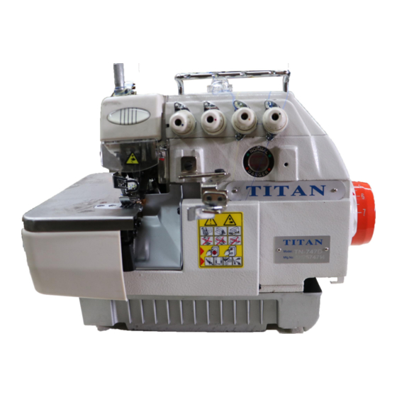
- Page 1 TN-700D Series Sewing Machine INSTRUCTION MANUAL...
-
Page 2: Preface
INSTRUCTIONS FOR TN-700 SERIES MACHINES PREFACE This manual has been prepared to guide you while operating TN-700 series machines and arranged to simplify ordering spare parts. This manual explains in detail the proper settings for operation of the machines. Illustrations are used to show the adjustments and reference letters are used to point out specific items discussed. -
Page 3: Table Of Contents
CONTENTS PREFACE .................................. 2 SAFETY RULES ................................. 4 GENERAL SAFETY ..............................5 IMPORTANT SAFETY INSTRUCTIONS ........................6 APPLICATION OF THIS INSTRUCTION MANUAL ...................... 6 STYLES OF MACHINES ............................. 7 TN-737D .................................. 7 TN-747D .................................. 7 TN-757D .................................. 7 PARTS OF THE MACHINE ............................8 INSTALLATION................................. -
Page 4: Safety Rules
SAFETY RULES IMPORTANT! Before putting the machine into service, also read the safety rules and instructions from the motor supplier. Explanation of safety labels Do not ignore this warning sign and do not proceed with incorrect operation. Doing so may cause serious personal injury. DANGEROUS Ignoring this warning sign and proceeding with incorrect operation will cause machine and/ or operator damage. -
Page 5: General Safety
GENERAL SAFETY When using these machines, basic safety precautions should always be followed to avoid the risk of fire, shock or personal injury. Follow all instructions in this manual to get the most out of your machine. • Keep your work area clean: Cluttered workspaces and benches can case injury and damage to machinery. -
Page 6: Important Safety Instructions
• Do not modify this machine without confirming this with your qualitied technician or with Titan Sewing directly. • When using this machine, all safety equipment and precautions should be in place to allow a safe environment for the machine and operator. -
Page 7: Styles Of Machines
STYLES OF MACHINES The TN-700 series of machine is normally split up into (3) categories but not limited to these. Future expansion may expand these categories TN-737D : This model is a 3 thread, single needle overcast only machine used traditionally for only overcasting the edge seams. -
Page 8: Parts Of The Machine
PARTS OF THE MACHINE (1) Lifting lever (2) Presser foot (3) Control box (4) Thread stand (5) Oil gauge window (6) Pulley (Hand Wheel) -
Page 9: Installation
INSTALLATION • Machine installation should only be carried out by a qualified technician. • Contact your dealer or a qualified electrician any electrical work that may need done. • The sewing machine weighs 48kg. The installation should carried out two or more people. - Page 10 • Install the pedal of motor (4)(Fig. 2) on the left side, and the pedal of presser foot lift (5) on the right side. Figure 2 • Install the waste chute and the thread stand as the part lists show. Figure 3...
-
Page 11: Handling Your Machine
HANDLING YOUR MACHINE When lifting your machine in and out of your table or any other situation, please refer to (Fig. 4) for how to lift your machine. DO NOT lift the machine by the left base arm as in (Fig. 5) Figure 4 Figure 5... -
Page 12: Break In Period
BREAK IN PERIOD Please operate this machine at 80% of the maximum speed the first tour weeks for engagement. This will help extend the life of your new machine and allow the machine to “break-in” all new parts. LUBRICATION Fill the lubrication oil (Fig. 6)(1) Remove the screw (1), and fill it with the included high speed oil. Tighten the screw (1) after the oil level indicator locates between the two marking lines. - Page 13 LUBRICATION (con’t) When changing the filter (yearly maintenance), the cover is held in place by (3) screws. This cover is on the backside of the machine. Figure 8...
-
Page 14: Threading
THREADING Follow the procedures for threading. Wrong threading may cause thread breaking, stitch skipping, puckering or unexpected sewing. For three thread only 737 (Fig. 9) - Page 15 THREADING (Con’t) For four thread only 747 (Fig. 10)
- Page 16 THREADING (Con’t) For five thread only 757 (Fig. 11)
-
Page 17: Tensions
TENSIONS The thread tension should be adjusted properly according to the kinds and the thickness of the materials, stitch length, and seam width, etc. In addition, adjust the nuts case by case individually. Turn the nuts clockwise will increase the thread tension. Otherwise, the thread tension will be decreased Thread tension adjusting nuts (Fig12) (1) The first adjusting knob controls double chain stitch threads (TN-757) or the left over-... -
Page 18: Needles
NEEDLES Figure 13 • Please use the needle DCX27 or the equivalents. • Loosen the screw and take off the needle. • Insert the new needle and push it up completely until the top of the needle is firmly seated as deep as it can travel into the needle bar. All needles should be installed with the scarf of the needle facing the back of the machine and the long groove faces your side. -
Page 19: Changing The Stitch Length
CHANGING THE STITCH LENGTH Figure 14 The stitch length is adjusted according to the fabrics, the differential ratio or other factors. Keep pressing the button (1) and turn the pulley till the button is locked. Then, release the button after reaching the desired stitch length. -
Page 20: Changing The Differential Feed
CHANGING THE DIFFERENTIAL FEED If the stroke of the main feed dog is larger than the stroke of the differential feed dog, the fabric will be extended while sewing. Otherwise, it will be shrunk Loosen the adjusting nut (1) Adjust the adjusting rod (2) downward will shrink the fabric, whereas move it upward will extend the fabric. -
Page 21: Adjusting / Replacing Blades
ADJUSTING / REPLACING BLADES Figure 16 REPLACE THE UPPER BLADE • Loosen the screw and move the lower blade holder to the left. Then, tighten the screw a little to hold the unit in place • Remove the screw and remove the old blade and put the new blade in. Then, tighten the screw a little to hold the unit in place •... -
Page 22: Adjust The Hem / Cutting Width
ADJUST THE HEM / CUTTING WIDTH • Turn the pulley to move the upper blade to the lower dead point. • Loosen the screw and move the lower trimmer holder to the left. Then, tighten the screw little to hold the unit in place •... - Page 23 TITANSEWING.CA 866-469-1147 SALES@TITANSEWING.CA...
Need help?
Do you have a question about the TN-700D Series and is the answer not in the manual?
Questions and answers