
Related Manuals for Pureline PL1616


Summary of Contents for Pureline PL1616
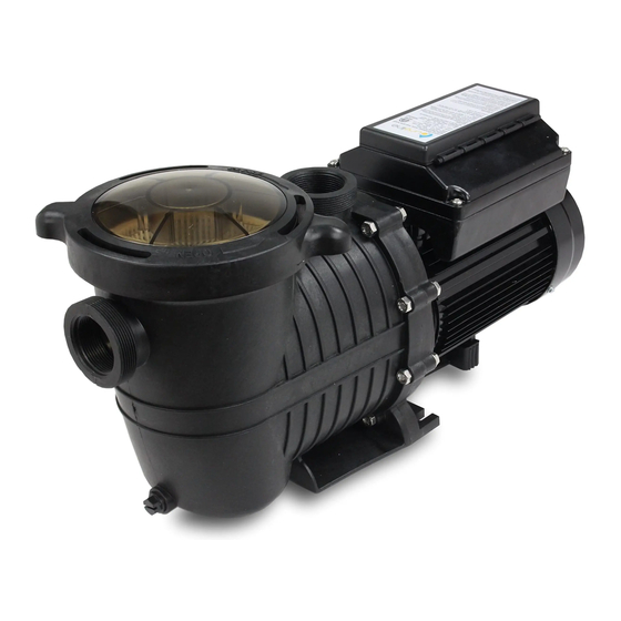
- Page 1 Pure Flow Variable Speed Pump Installation And User Guide Model: PL1616 Important Safety Instructions. Read And Follow All Instructions. Save Instructions.
-
Page 2: General Warnings
READ AND FOLLOW ALL INSTRUCTIONS ATTENTION INSTALLER: This manual contains essential information about the installation, operation, and safe use of this pool pump. Please remember to furnish this manual and all other instructional documents to the end user of this product. Failure to read and follow instructions can result in serious injury. -
Page 3: Pump Overview
WARNING- This unit must only be connected to a supply circuit that is protected by a ground-fault-circuit protection (GFCI). The GFCI should be provided by the installer and should be tested on a routine basis. To test the GFCI, simply push the test button. The GFCI should interrupt power. -
Page 4: Pump Installation
General Features ● Variable speed pumps provide maximum energy savings ● Simple interface that is easy to operate and program ● Real-time clock with 24-hour memory ● Removable strainer basket with a built-in thermal overload protection ● Totally-enclosed fan cooled (TEFC) motor Pump Installation Before servicing, all water circulation systems and pump controls must be in the off position, release all the pressure from the system. - Page 5 Pump Plumbing There are many different ways a pool pump can be plumbed due to space requirements, existing plumbing, water features, etc... Due to these scenarios, we have listed some general best practices to adhere to when plumbing a pool pump. Pool Plumbing Best Practices ●...
- Page 6 Improper Installation Filter 90° on suction side of pump Pump Pump Discharge Port Filter Ideally no 90° within 12’’ of pump suction port Pump Suction Port 90° 90° 3 Way Valve Piping 1. Larger piping sizes improve pool plumbing. 2. Piping on the suction side of the pump should be the same or larger than the return port. 3.
- Page 7 Electrical Requirements 1. Install all equipment in accordance with the National Electrical Code and all applicable local codes and ordinances. 2. A means for disconnection must be incorporated in the fixed wiring in accordance with the wiring rules. Voltage The voltage at the motor must NOT be more than 10% above or below motor nameplate rated voltage or the motor may overheat, causing the overload tripping.
-
Page 8: Start-Up And Operation
Screw 1: Ground wire Screws 2 & 3: Either of two live wires Screws 4 & 5: Not used 1. Remove the AC power connection terminal box cover. There are a total of 5 screws inside the terminal box. 2. Ensure that the available electrical supply is suitable for the motor’s voltage, phase, cycle, and that the wire size is adequate for the HP rating and distance from the power source. - Page 9 ATTENTION- Before removing strainer cover: 1. STOP PUMP before proceeding. 2. CLOSE VALVES in suction and outlet pipes 3. RELEASE ALL PRESSURE from pump and piping system using filter manual air relief valve. Priming Pump All suction and discharge valves must be open as well as filter air relief valve when starting the circulat- ing pump system.
-
Page 10: Using The Control Panel
Maintenance ● Clean strainer basket regularly. Do NOT strike the basket to clean. Inspect strainer cover gasket regularly and replace as necessary. ● Pumps have self-lubricating motor bearings and shaft seals. No lubrication is necessary. ● Keep the motor clean. Ensure air vents are free from obstruction to avoid damage. Do NOT use water to hose off the motor. - Page 11 Controls and LEDs 1. 1 Button/LED: When in Manual Mode, button 1 means manual speed 1. When in Schedule Mode, this button means cycle 1. The LED lights ON means the pump is running at Speed 1 in Manual Mode or running at cycle 1 in Schedule Mode. 2.
-
Page 12: Operating The Pump
Alarm: LED is on if an alarm condition occurs. Operating The Pump This section details how to operate the pump using the control panel buttons. Starting The Pump 1. Make sure the pump's power is ON and the green ON power LED is illuminated. 2. -
Page 13: Basic Parameters
Programming Each Cycle 1. Go to Schedule Mode by pressing the “Mode” button until it reads “Schedule Cycle.” 2. Press the “Quick Set” button to go into the speed setting page of cycle 1. 3. Change the speed by pressing the arrow and “+ / -” button. 4. -
Page 14: Maintenance
Maximum Speed: You can run the pump at maximum speed. The factory-set minimum speed is 3450 RPMs. 8. Make sure the screen is on the home page. 9. Press the “INV” button to show the pump’s performance data. 10. Press the “Quick Set” button for the settings page. 11. - Page 15 Troubleshooting Your Pump Issue Solutions The motor will not start 1. Check for Incorrect wiring and loose electrical connections. 2. Check switches, relays fuses, circuit breakers, and GFCI’s. Replace if necessary. 3. Manually rotate the shaft from the back of the motor to make sure it isn’t stuck.
- Page 16 Description Part Number Pump Cover PL1585 Cover O-ring PL1586 Pump Basket PL1636 Pump Housing PL1632 Diffuser O-ring PL1628 Diffuser PL1627 Impeller 1.5 HP PL1637 Pump Housing O-ring PL1625 Seal Plate PL1631 Housing Bolts PL1623 Shaft Seal Assembly PL1592 Drain Plug Assembly PL1629 Base Bracket PL1620...
Need help?
Do you have a question about the PL1616 and is the answer not in the manual?
Questions and answers