Table of Contents
Advertisement
Quick Links
Advertisement
Table of Contents

Related Manuals for Pureline PL2517


Summary of Contents for Pureline PL2517
- Page 1 VARIABLE SPEED PUMP INSTALLATION AND USER'S INSTRUCTIONS...
-
Page 2: Table Of Contents
TABLE OF CONTENTS SAFETY INSTRUCTIONS ..............................3 PUMP OVERVIEW ................................6 Pump Overview ......................................... 6 General Features ............................................. 6 Controller Features ............................................6 Controller Overview ......................................... 7 CONTROL PANEL OVERVIEW ............................7 Keypad Navigation ........................................8 INSTALLATION ..................................8 Location ............................................8 Piping ............................................. -
Page 3: Safety Instructions
SAFETY INSTRUCTIONS IMPORTANT NOTICE This manual offers installation and operation instructions of this pump for user. This manual includes important information about correct installation, operation and safe use of this pump. This manual should be left to the owner of the pump or near the pump after installation. This manual contains important information to help you with operation and maintenance. - Page 4 General Warnings The control unit on the pool pump motor contains hazardous voltage. Never open the inside of the drive motor enclosure. The pump is not submersible. The pump is capable of high flow rates. Be careful when installing and programming to limit pumps performance ...
- Page 5 IMPORTANT: DANGEROUS PRESSURE: STAND CLEAR OF PUMP AND FILTER DURING START UP When pressure testing a system with water, air is often trapped in the system during the filling process. This air will compress when the system is pressurized. Should the system fail, this trapped air can propel debris at a high speed and cause injury.
-
Page 6: Pump Overview
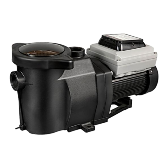
PUMP OVERVIEW Pump Overview Variable speed pump is the perfect choice for all in-ground swimming pools. It is specially designed for all kinds of ground swimming pools. It is also your best choice. Thick walled body parts, a heavy duty TEFC motor, and highly engineered hydraulics make this rugged and tested design perfect for any pool, spa, water feature, or fountain. -
Page 7: Controller Overview
Controller Overview The Variable Speed Pump uses a premium efficiency variable speed motor that provides tremendous program flexibility in terms of motor speed and duration settings. The pump is intended to run at the lowest speeds needed to maintain a sanitary environment, which in turn minimizes energy consumption. Pool size, the presence of additional. This pump is for use with 230 Vrms nominal, and in pool pump applications ONLY. -
Page 8: Keypad Navigation
Keypad Navigation Speed Buttons - Used to select the run speed desired. The LED above the Speed Buttons will illuminate when that speed is selected or is currently running. A flashing LED indicates is active on that speeds channel. Mode select Button – Choose manual and schedule Start/Stop Button - Used to Start and Stop the pump. -
Page 9: Piping
Piping For improved pool plumbing, it is recommended to use a larger pipe size. Piping on the suction side of the pump should be the same or larger than the return line diameter. Plumbing on the suction side of the pump should be as short as possible. For most installations, always INSTALL a valve on both the pump suction and return lines so that the pump can be isolated during routine maintenance. -
Page 10: Electrical Requirements
Electrical Requirements All installation must conform to the National Electrical Code and all applicable local codes and ordinances. A means for disconnection must be incorporated in the fixed wiring in accordance with the wiring rules. RISK OF ELECTRICAL SHOCK OR ELECTROCUTION. Variable Speed Pump must be installed by a licensed electrician or a qualified service professional. -
Page 11: Operating The Pump
NOTICE: For Canada, a 6 AWG or larger solid copper bonding conductor is required. The pump should be permanently connected to either a circuit breaker, 2-pole timer or 2-pole relay. If AC power is supplied by a GFCI circuit breaker, use a dedicated circuit breaker 3-that has no other electrical loads. Connect the pump permanently to a circuit. -
Page 12: Using The Default Schedule
Using the Default Schedule The default schedule is designed to provide enough daily turnover to service a typical pool. See Table 2 for default schedule. Table 2: Default Schedule. SPEED 1 is set to begin at 8:00am and run at 3000 RPM for a duration of 2 hours. When SPEED 1 is complete the pump immediately begins running the default SPEED 2. - Page 13 Figure 7: Setting Speed 3. Use the “+” and “-” arrows to adjust the speed in RPM for SPEED 1. NOTICE: Speed is adjusted up or down by increments of 10 RPM. 4. Press the “1” button again and the display will change to SPEED 1 start time. The “Time” parameter LED will begin to blink.
-
Page 14: Speed Priorities
Pressing the “1” button will continue to cycle through these parameters, but the changes are immediately saved as they are adjusted. Press the “2” button. The LED above SPEED 2 will begin to flash and the corresponding parameter LED will flash while editing. -
Page 15: Operating The Pump While Running
Operating the Pump While Running If power is connected to the pump motor, pressing any of the following buttons referred to in this section could result in the motor starting. Failure to recognize this could result in personal injury or damage to equipment. Pressing the Display button will cycle through the current parameters. -
Page 16: Winterizing
Put the basket back into the housing. Be sure to align the notch in the bottom of the basket with the rib in the bottom of the volute. Fill the pump pot and volute up to the inlet port with water. Clean the cover, O-ring, and sealing surface of the pump pot. -
Page 17: Servicing
SERVICING Be sure that disconnect power to the Variable Speed Pump at the circuit breaker and disconnect the communication cable before servicing the pump. Electrical shock can cause serious or fatal injury. Read all servicing instructions before working on the pump. DO NOT open the strainer pot if pump fails to prime or if pump has been operating without water in the strainer pot. -
Page 18: Pump Disassembly
Pump Disassembly All moving parts are located in the rear sub-assembly of this pump. Tools required: 3/8 inch socket or open end wrench. Phillips screwdriver. Flat blade screwdriver. To remove and repair the motor subassembly, follow the steps below: Press the Start/Stop button to stop the pump and turn off the pump circuit breaker at the main panel. -
Page 19: Restart Instructions
Remount the seal plate to the motor mounting plate. Before installing the rotating part of the seal on the impeller shaft, wet the impeller shaft with soapy water and slide the seal to the impeller shaft end. Remove the dirt from the contact surface of the seal with a clean cloth. Screw impeller onto the motor shaft (clockwise to tighten). -
Page 20: Troubleshooting
TROUBLESHOOTING Diagnosing certain symptoms may require close interaction with, or in close proximity to, components that are energized with electricity. Contact with electricity can cause death, personal injury, or property damage. When trouble shooting the pump, diagnostics involving electricity should be cared for by a licensed professional. Problem Possible Cause Corrective Action... -
Page 21: Errors And Alarms
Troubleshooting (Cont.) Problem Possible Cause Corrective Action Pump runs without Impeller is loose Check that pump is spinning by looking at fan on back flow. Air leak of Variable Speed Pump. If so, check that pump Clogged or restricted plumbing impeller is correctly installed. -
Page 22: Replacement Parts
Qty. 9.01.010000.009 Strainer cover Kit cover O-ring 9.01.010000.015 Basket 9.01.010000.002 9.01.010000.001 Strainer Housing for PL2515 Series 9.01.020000.001 Strainer Housing for PL2517, PL2518,PL2516,PL2519 Diffuser 9.01.010000.003 9.01.010000.010 Impeller for PL2517 or PL2515 9.01.010000.011 Impeller forPL2518 9.01.010000.012 Impeller for PL2516 9.01.010000.013 Impeller for PL2519 Seal Plate 9.01.010000.004... -
Page 23: Pump Performance Curves
Pump Performance Curves PL2515 Pump Dimensions Model Specifcationes Overall Ratings Model PL2515 Input Voltage 230 V Input Frequency Single phase, 50 or 60 Hz Input Current 5.5A Maximum Continuous Load 1.5HP Speed Range 450 - 3450 RPM Environmental Rating NEMA Type 3 1.5"x1.5"... - Page 24 Pump Performance Curves PL2517 PL2518 PL2519 PL2516 Pump Dimensions Model Specifcationes Overall Ratings Model PL2517 PL2518 PL2516 PL2519 Input Voltage 230 V Input Frequency Single phase, 50 or 60 Hz Input Current 5.5A Maximum Continuous Load 1.5HP Speed Range 450 - 3450 RPM...
-
Page 25: Limited Warranty
Limited Warranty Service Information Inyo Holdings LLC is staffed with trained personnel to provide customers with reliable pool service. Whether you need technical advice, repair, or genuine factory replacement parts, please contact us. Phone: Email: Limited Warranty Limited Two-Year Warranty Inyo Holdings LLC warrants this product to be free from defects in material or workmanship for a period of two(2) years following the date of purchase.
Need help?
Do you have a question about the PL2517 and is the answer not in the manual?
Questions and answers