Table of Contents
Advertisement
Quick Links
Advertisement
Table of Contents

Related Manuals for Hochiki HCVX


Summary of Contents for Hochiki HCVX
- Page 1 HCVX Fire Control Panel Installation and Operation Manual H o c h i k i H C V X F i r e C o n t r o l P a n e l I s s u e D a t e : J u n e 2 0 1 6 I n s t a l l a t i o n a n d O p e r a t i o n M a n u a l M a n - 1 1 9 4 H A, R e vi s i o n E 0 1 .
- Page 2 Hochiki HCVX Fire Control Panel Models of the HCVX Fire Control Panel are suitable as follows: Without integrated dialer and conventional detection for 2 Zone (HCVX-2R/115V or 230V), 4 Zone (HCVX-4R/115V or 230V) or 8 Zone (HCVX-8R/115V or 230V) ...
- Page 3 Copyright © 2016 by Hochiki America All rights reserved. Hochiki is a registered trademark of Hochiki America All other product or service names are property of their respective owners. H o c h i k i H C V X F i r e C o n t r o l P a n e l I n s t a l l a t i o n a n d O p e r a t i o n M a n u a l M a n - 1 1 9 4 H A, R e vi s i o n E 0 1 .
-
Page 4: Table Of Contents
Part Numbers ............................7 Writing Styles ............................7 If You Need Help ............................ 7 Contacting Hochiki America Technical Support .................. 7 RMA Returns Required ......................... 8 Warranty Returns ..........................8 Product Return Address ........................8 Overview .................... - Page 5 TELCO Line Connections ........................38 Aux 24V ..............................39 ALM RES .............................. 39 RS485 ..............................39 Connecting the HCVX Annunciator ....................39 Testing the Installation ...................... 40 Troubleshooting ......................... 40 Programming and Operating ..............42 ...
- Page 6 Operating Environment ...................... 74 Physical Specifications ...................... 74 Equipment List ..................75 Hochiki HCVX Fire Control Panel HCVX Fire Control Panels ..........75 Supporting Components and Replacements ..............76 Compatibility Identifier ........................78 Detectors ........................... 78 ...
- Page 7 Index ......................100 H o c h i k i H C V X F i r e C o n t r o l P a n e l I n s t a l l a t i o n a n d O p e r a t i o n M a n u a l M a n - 1 1 9 4 H A, R e vi s i o n E 0 1 .
-
Page 8: Introduction
Models including dialer communication are the 2 zone HCVXD-2R, 4 zone HCVXD-4R and 8 zone HCVXD- Models excluding dialer communication are the 2 zone HCVX-2R, 4 zone HCVX-4R and 8 zone HCVX-2R. Power supply options of these models are available for 115 VAC or 230 VAC and cabinet colors are available in red. -
Page 9: Using This Manual
Operating Instructions provides an overview of HCVX Fire Control Panel status and control Appendix D instructions. Related Documentation The following documentation shall be used for installing and operating models of the HCVX Fire Control Panel: Installation and Operation Manual, Man-1194HA, Revision E01.XX ... -
Page 10: Document Conventions
Writing Styles Before you begin using the HCVX Fire Control Panel, familiarize yourself with the stylistic conventions used in this manual: Denotes a displayed variable, a variable that you must type, or is used for emphasis. -
Page 11: Rma Returns Required
Warranty products that have been placed in service will be repaired or replaced by Hochiki America..Warranty products that have not been placed in service will be returned to Hochiki America stock and an equivalent credit will be provided to the contractor. - Page 12 Prominently display the RMA number on all packages sent to Hochiki America Corporation for return. Ship all return products to: Attention: RMA # Hochiki America Corporation 7051 Village Drive, Suite 1oo Buena Park, CA 90621 H o c h i k i H C V X F i r e C o n t r o l P a n e l I n s t a l l a t i o n a n d O p e r a t i o n M a n u a l M a n - 1 1 9 4 H A, R e vi s i o n E 0 1 .
- Page 13 Overview This page intentionally left blank H o c h i k i H C V X F i r e C o n t r o l P a n e l I n s t a l l a t i o n a n d O p e r a t i o n M a n u a l M a n - 1 1 9 4 H A, R e vi s i o n E 0 1 .
-
Page 14: Overview
The fire control panel provides Class B zone detection under default conditions and Class A loop detection on one zone when configured. Default zones of the HCVX Fire Control Panel can operate as NFPA 72 Class B, Style C or NFPA 72, Class B, Style B. - Page 15 Power internal battery charger. Models of the HCVX Fire Control Panel accept 7 AH or 12 AH valve-regulated, lead-acid batteries and operate in special application modes for power inputs of 115 VAC or 230 VAC. H o c h i k i H C V X F i r e C o n t r o l P a n e l I n s t a l l a t i o n a n d O p e r a t i o n M a n u a l M a n - 1 1 9 4 H A, R e vi s i o n E 0 1 .
-
Page 16: Hardware Features
Overview Hardware Features The figure below illustrates hardware features of the HCVX Fire Control Panel: Figure 2-2 Hardware Features Item Description The Main Terminal Block accepts input power and transformer primary Main Terminal Block connections. The Main Terminal Block contains a 3.15 Amp slow-blow and Fuse Holder fuse rated for 250 VAC. -
Page 17: Internal Power Supply
Overview Internal Power Supply The internal power supply of the HCVX Fire Control Panel meets UL 864, 9th edition and provides a 4 Amp, linear power-source for operating FACP functions as well as charging the standby batteries. Reference Appendix C, Calculations to determine load current limitations of the 4 Amp power supply. -
Page 18: Panel Controls And Indicators
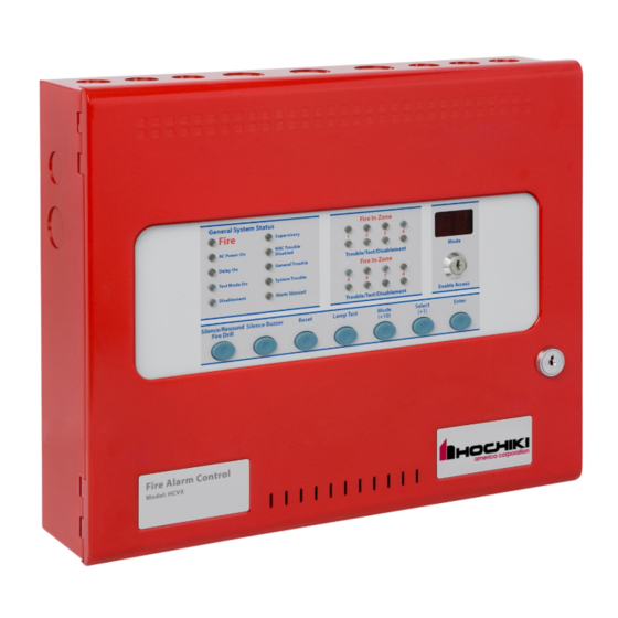
Overview Panel Controls and Indicators The fascia of the HCVX Fire Control Panel is divided into sections for controls and indicators. The figure below illustrates controls and indicators of the HCVX Fire Control Panel: Figure 2-3 Controls and Indicators General System Status... - Page 19 Overview Upper Indicators The figure below illustrates upper indicators of the HCVX Fire Control Panel: Figure 2-4 Upper Indicators General System Status Alarm In Zone Fire Supervisory NAC Trouble AC Power On Disabled Mode Trouble/Test/Disablement Delay On General Trouble Alarm In Zone...
- Page 20 Overview Upper Indicators LED Color Alarm In Zone Yellow Trouble/Test/Disablement Alarm Yellow Trouble/Test/Disablement Alarm Yellow Trouble/Test/Disablement Alarm Yellow Trouble/Test/Disablement Alarm Alarm In Zone Yellow Trouble/Test/Disablement Alarm Yellow Trouble/Test/Disablement Alarm Yellow Trouble/Test/Disablement Alarm Yellow Trouble/Test/Disablement Alarm Two Seven-Segment LEDs The Mode display contains two seven-segment LEDs for Mode programming configurations and identifying status conditions.
- Page 21 Access Level 2. Trouble events are non-latching inputs and cannot be cleared by the Reset button. Non-latching inputs are cleared when faults are cleared. Tests fascia indicators and the internal buzzer of the HCVX Fire Control Panel by Lamp Test illuminating all LEDs while sounding the buzzer.
- Page 22 Overview Lower Indicators The figure below illustrates the lower indicators of the HCVX Fire Control Panel: Figure 2-6 Lower Indicators W/Dog Mains Batt. Aux.24V Batt. Comms Earth Sys.Fuse NAC1 NAC2 Fail Fail Trbl. Trbl. Trbl. Trbl. Trbl. Trbl. Trbl. Trbl.
- Page 23 Overview Upper Controls The figure below illustrates upper controls of the HCVX Fire Control Panel: Figure 2-7 Upper Control General System Status Alarm In Zone Fire Supervisory NAC Trouble AC Power On Disabled Mode Trouble/Test/Disablement Delay On General Trouble Alarm In Zone...
-
Page 24: Field Terminals
Overview Field Terminals The figure below illustrates field terminals of the HCVX Fire Control Panel: Figure 2-9 Field Terminals NC C NC C NC C NAC POWER POWER AUX 24V ALM RES RS485 NAC1 NAC2 Z1 RET TRBL SUPV. FIRE... - Page 25 DIALER BOARD CONNECTIONS The Dialer Board is an optional feature on models of the HCVX Fire Control Panel. Reference Appendix A, Specifications for operating characteristics of these terminals. H o c h i k i H C V X F i r e C o n t r o l P a n e l I n s t a l l a t i o n a n d O p e r a t i o n M a n u a l M a n - 1 1 9 4 H A, R e vi s i o n E 0 1 .
-
Page 26: Optional Dialer Board
The Dialer Board is an optional DAC (Digital Alarm Communicator) feature provided on specific models of the HCVX Fire Control Panel. The Optional Dialer Board connects to the Main Board of the fire control panel and communicates status and alarm conditions to digital receivers. -
Page 27: Installation
Installation Section 3 Installation This section provides instructions for connecting cables, mounting and testing the HCVX Fire Control Panel for installation. Install this product in accordance with NFPA 72, the National Electrical Code and all local codes. General Installation Checklist To complete the installation: Create a plan for the fire alarm system and provide a checklist for installing the fire control panel. -
Page 28: Before You Begin
Electronic components within the HCVX Fire Control Panel are vulnerable to damage caused by electrostatic discharge. Ground straps must be worn by installers before handling electronic components to prevent this damage. Acquire the following items that are not included with the HCVX Fire Control Panel, but may be required for the installation: Item... -
Page 29: Determining System Current Draw
Current-loading in a fire control system can be caused by individual or multiple combinations of zone circuits, signaling line circuits, notification appliances, initiating devices and cabling. Select circuit devices and cabling for the fire control system that does not exceed the current driving capability of the HCVX Fire Control Panel. -
Page 30: Removing The Fascia
Installation Removing the Fascia Remove the fascia of the HCVX Fire Control Panel prior to the mounting process to prevent damage to circuit board components. To remove the fascia from the cabinet-box of the HCVX Fire Control Panel: Remove the mounting-screw on the right-side of the fascia. -
Page 31: Separation Of Circuits
¼ inch spacing between non-power and power limited circuit conductors. All circuits of the HCVX Fire Control Panel are power limited accept AC input, AC output, battery, transformer input, transformer output, bridge rectifier input and bridge rectifier output. -
Page 32: Ac Cabling
Separation of Non-Power Limited and Power Limited Circuit-Cabling AC Cabling Power cabling from the mains to the HCVX Fire Control Panel must provide connections to branch circuits containing a 15 Amp fuse. Specify 14 AWG wiring for this connection. Power cabling must enter the back, top or left-side of the fire control panel cabinet through the cabinet- knockouts. -
Page 33: Standby-Battery Cabling
Connect AC cabling from the power-source to the main terminal block. The main terminal block is located on the top-left of the HCVX Fire Control Panel. Wiring from the power-source must include a secure earth-ground connection from the building-ground to the fire control panel and must enter the fire control panel cabinet as close as possible to the main terminal block. - Page 34 Figure 3- 5 Standby-Battery Connections The series connection illustrated provides a standby voltage of 24 VDC required by the HCVX Fire Control Panel. H o c h i k i H C V X F i r e C o n t r o l P a n e l I n s t a l l a t i o n a n d O p e r a t i o n M a n u a l M AN - 1 1 9 4 H A, R e vi s i o n E 0 1 .
-
Page 35: Field Cabling
S2027. Place the 6.8K Ohm EOL resistor across the last device in the detection zone circuit to provide this supervision. Zones of the HCVX Fire Control Panel operate NFPA 72 Class B, Style C or NFPA 72, Class B, Style B. Style C devices provide trouble conditions for direct shorts and opens on zone loops. -
Page 36: Alm Res
Figure 3- 6 Detector and Pull Station Connection Zones of the HCVX Fire Control Panel are not listed to operate more than one detector in the alarm condition. Reference Appendix B, Detectors for the maximum number of devices permitted per circuit. -
Page 37: Nac 1 And Nac 2
S2028 across the last device on the circuit. NAC circuits must be wired as a single circuit to enable the supervising circuit to operate. NAC circuits must also be wired in a daisy-chain without T-Tap connections. NAC outputs of the HCVX Fire Control Panel accept devices that are polarized only. A trouble condition is reported when non- polarized NAC devices are connected to these NAC outputs. -
Page 38: Relay Outputs
Reference Appendix A, Specifications for relay ratings of HCVX Fire Control Panel. Optional Dialer Board The Optional Dialer Board is an optional feature provided on specific models of the HCVX Fire Control Panel. Mount the Optional Dialer Board on the Main Board of the HCVX Fire Control Panel. - Page 39 Installation To mount the Optional Dialer Board of the HCVX Fire Control Panel: Locate the left area of the Main Board to connect and secure the Optional Dialer Board. The left area of the Main Board contains fuse F3, internal buzzer BZ1 and connector J1.
- Page 40 DIALER BOARD CONNECTIONS Mode Reference Appendix B, Equipment List for HCVX Fire Control Panel models supporting the Optional Dialer Board. Reference Appendix A, Specifications for wire gages acceptable for these terminal block connections. H o c h i k i H C V X F i r e C o n t r o l P a n e l I n s t a l l a t i o n a n d O p e r a t i o n M a n u a l M AN - 1 1 9 4 H A, R e vi s i o n E 0 1 .
-
Page 41: Telco Line Connections
Installation TELCO Line Connections The figure below illustrates TELCO line 1 and line 2 connections of the Optional Dialer Board: Figure 3- 12 TELCO Line Connections The table below describes the TELCO color conventions illustrated in figure 3-12: Terminal Color Green Brown Gray... -
Page 42: Aux 24V
The RS485 communication bus provides no connection and is reserved for future use. Connecting the HCVX Annunciator Connect the HCVX Annuciator to the HCVX Fire Control Panel for remote annunciation. Reference Appendix B, Equipment List for models of the HCVX Annunciator. -
Page 43: Testing The Installation
Troubleshoot the HCVX Fire Control Panel when conflicts exist after installing or configuring. Monitor the lower fascia indicators of the fire control panel to determine the cause of the trouble condition. The lower indicators of the fascia are visible after opening the cabinet-door of the HCVX Fire Control Panel. - Page 44 Installation Indicator Description Illuminates when the fire control panel is operating on batteries and the battery voltage is Batt Low below 21.5 VDC. Illuminates when the fire control panel is operating on AC and the battery voltage is below 24 VDC. Communication has been lost with the remote annunciator or Ancillary board.
-
Page 45: Programming And Operating
Programming and Operating Section 4 Programming and Operating Notice to Users, Installers, Authorities Having Jurisdiction, and other involved parties. This product incorporates field-programmable software. In order for the product to comply with the requirements in the Standard for Control Units and Accessories for Fire Alarm Systems, UL 864 10th Edition, certain programming features or options must be limited to specific values or not used at all as indicated below. - Page 46 Programming and Operating Program Feature or Option Permitted in UL 864 Possible Settings Settings Permitted ? (Y / N) In UL 864 Set / Clear Set / Clear Remove AUX 24V On Fire Alarm Code: 28 Set / Clear for each Clear all zones Set Z1-Z8, Zone Alarm Delayed zone...
-
Page 47: Programming The Fire Control Panel
The Mode LED display on the fascia of the fire control panel provides the configuration menu. Open the menu through Access Level 2 and Access Level 3 of the HCVX Fire Control Panel. Open Access Level 2 by turning the Enable Access key to the right. Open Access Level 3 by moving the Write Enable slide-switch to the left. -
Page 48: Navigate The Menu
Navigate the menu on the Mode LED display using the Mode (+10), Select (+1) and Enter buttons of the HCVX Fire Control Panel. The Mode LED, Mode (+10), Select (+1) and Enter buttons are located on the center of the fascia. - Page 49 The fire control panel beeps three-times to indicate entry in Access Level 3. The beeping continues to indicate Access Level 3 operation. The figure below illustrates the Write Enable switch on the fascia of the HCVX Fire Control Panel: Figure 4- 3 Write Enable Slide-Switch Code 00 is displayed on the menu of the Mode LED after entering Access Level 3.
- Page 50 Programming and Operating Choose code 00 from the menu and press Enter to set the code. A flashing dot is displayed in the lower-right-corner of the Mode LED to identify the set code. The figure below illustrates a code 00 set and code 00 not set in the menu: Figure 4- 4 Code 00 Set and Code 00 Not Set A flashing dot is shown in the left...
-
Page 51: Configuration Codes
Normal Standby condition. Configuration Codes Not all configuration codes of the HCVX Fire Control Panel are authorized for operation under UL 864. Reference Appendix G, UL 864 Permitted Configurations for the list of authorized configuration codes of the HCVX Fire Control Panel. - Page 52 Programming and Operating Code Function Description Set Steady Alarm Mode Sets NAC output to steady On Set March Time Alarm Mode Sets the frequency of the NACs for the March Time coding pattern of ½ second on, ½ second off and then repeat.
- Page 53 Programming and Operating Code Function Description Remove Aux 24 V Sets the AUX 24 V output to switch off during a fire On Fire Alarm alarm condition. Set Z1, Alarm Delayed These functions are not UL recognized. Sets an alarm delay from the detector to the zone based Set Z2, Alarm Delayed on Alarm Delay codes 0-9.
- Page 54 Programming and Operating Code Function Description Set Z1, Coincidence These functions are not supported. Setting this function enables Zone Coincidence. Set Z2, Coincidence Set Z3, Coincidence Set Z4, Coincidence Set Z5, Coincidence Set Z6, Coincidence Set Z7, Coincidence Set Z8, Coincidence Set Z1, Configure I.S.
- Page 55 Programming and Operating Code Function Description Set Z1, Short Circuit Triggers Alarm The default condition of this function reports short-circuits as activations under Class A, Style D or Class B, Style B. Set Z2, Short Circuit Triggers Alarm Setting this function changes from reporting Set Z3, Short Circuit Triggers Alarm short-circuits as activations to reporting short-circuits as trouble conditions under Class A, Style E or Class B,...
- Page 56 Programming and Operating Code Function Description Set Z1, Alarm Generates Supervisory Fire is reported when this code is cleared. Supervisory is reported when this code is set. Set Z2, Alarm Generates Supervisory Set Z3, Alarm Generates Supervisory Set Z4, Alarm Generates Supervisory Set Z5, Alarm Generates Supervisory Set Z6, Alarm Generates Supervisory Set Z7, Alarm Generates Supervisory...
- Page 57 Set Z5, Fire Relay Deactivated Set Z6, Fire Relay Deactivated Set Z7, Fire Relay Deactivated Set Z8, Fire Relay Deactivated Functions and Codes Functions and codes for operating the HCVX Fire Control Panel in Access Level 2 are described below: Function Terminal Codes Description...
- Page 58 Programming and Operating Function Terminal Codes Description Select codes d1 through d8 to disable Zones 1 through Disable Zones 8. Disabling Zones does not provide fire or trouble indications on the fire control panel. The Disablement and Zone Trouble/On Test/Disabled indicators illuminate when zones 1 through 8 are disabled.
-
Page 59: Control Operation
Programming and Operating Control Operation The table below describes control operation of the HCVX Fire Control Panel: Controls Operation Press the W / Dog Reset button to clear the watchdog event. The watchdog W / Dog Reset event causes a reset when the fire control panel fails to carry out an operation. -
Page 60: Silence/Resound Fire Drill
NACs to operate again. The NACs can be toggled on and off with the Silence/Sound alarm button as required. Reset The reset command restores operation of the HCVX Fire Control Panel from an alarm or trouble condition. Zone Trouble Removal of a detector from its base or a trouble on any of the zone wiring will cause the Trouble LED and Zone Trouble LEDs to flash, indicating the zone in which the trouble has occurred. -
Page 61: Test Mode
Programming and Operating Test Mode To operate Test Mode: Turn the Enable Access key to the right to enter Access Level 2. Code t1 is displayed on the Mode LED. The figure below illustrates code t1 on the Mode LED: Figure 4- 6 Code t1 on the Menu Mode... -
Page 62: Disablements
Re-enable zones following the disabling process. Disabling Zones To disable zones on the HCVX Fire Control Panel: Turn the Enable Access key to the right to obtain Access Level 2 of the menu. Press Mode (+10) until “d1” appears in the first field of the LED display. -
Page 63: Alarm Delays
Programming and Operating Disable NAC Outputs To disable NAC outputs: Turn the Enable Access key to the right to open Access Level 2. Press the mode button to select “db” on the seven segment display. Press Enter to disable all NAC outputs and cause the Disablement and NAC Trouble/ Disabled LEDs to light. Disable Trouble Contact To disable a trouble relay contact: Turn the Enable Access key to the right to enter Access Level 2. -
Page 64: Relay Operation
Reference Default Operation before programming these alarm delay settings. Relay Operation The HCVX Fire Control Panel provides volt free changeover relay contacts for local control and signaling. The relay contacts are rated for switching signaling circuits only and the maximum ratings should not be exceeded under any circumstances. -
Page 65: Maintenance And Repair
Cleaning the External Cabinet and Fascia-Door Clean the external cabinet and fascia-door of the HCVX Fire Control Panel with a damp cloth. Do not clean these surfaces with detergents or solvents. Do not permit water to enter the cabinet during the cleaning process. -
Page 66: Installing The Standby-Batteries
Reference Section 3, Installation for installing the standby-batteries. Replacing Fuses The HCVX Fire Control Panel contains a battery fuse, a transformer fuse and an AC input fuse to protect it against circuit overloads. A 6.3 Amp slow-blow fuse protects the battery charging circuit and the transformer secondary. -
Page 67: Transformer Fuse
Re-connect the red-lead of the recharging circuit to the positive terminal of the standby-batteries. Close the fascia-door of the HCVX Fire Control Panel. Connect NAC Power and Power inserts from the fascia terminal strip of the HCVX Fire Control Panel. Turn on 115 VAC or 230 VAC at the power source. -
Page 68: Ac Input Fuse
Test the fire control panel by operating it to determine that it functions. AC Input Fuse The following procedures describe methods for removing and installing the 5 AC input fuse of the HCVX Fire Control Panel. Removing the AC Input Fuse To remove the 5 Amp AC input fuse: Turn off 115 VAC or 230 VAC at the power source. -
Page 69: Replacing Cabinet Components
Secure the retaining-screw to the fascia-door and the cabinet of the HCVX Fire Control Panel. Connect NAC Power and Power inserts from the fascia terminal strip of the HCVX Fire Control Panel. Secure the retaining-screw to the fascia-door and the cabinet of the HCVX Fire Control Panel. -
Page 70: Specifications
Specifications Appendix A Specifications This appendix provides electrical and environmental specifications of the HCVX Fire Control Panel. Electrical AC Line Connection Terminals Description Voltage AC Line 115 VAC @ 50 / 60Hz (Supervised), 170 VA Maximum 230 VAC @ 50 / 60Hz (Supervised) ), 170 VA Maximum... -
Page 71: Maximum Current Draw
Specifications Maximum Current Draw The maximum current draw of the HCVX Fire Control Panel cannot exceed 5.18 A. Outputs of the fire control panel can be loaded with combinations of currents as long as the total does not exceed 4.5 A. - Page 72 Current Loading Limitations Standby-batteries of the HCVX Fire Control Panel are rated for 7 AH or 12 AH of operation. Standby and alarm current of the HCVX Fire Control Panel can include all or part of the following loads: Loads...
-
Page 73: Field Wiring
Current loading calculations do not include the combined IDC currents of the HCVX Fire Control Panel. These combined IDC currents are negligible in comparison to fire control panel, ancillary device and NAC currents of the HCVX Fire Control Panel and are therefore excluded from the current loading calculation. - Page 74 Battery leads are provided in the cabinet for recharging the standby-batteries. One end of the battery leads are permanently connected to the power supply of the HCVX Fire Control Panel. The opposite end of the battery leads connect to terminals of the standby-batteries.
-
Page 75: Initiating Device Circuit (Idc) Ratings
Reference Appendix B, Equipment List, Detectors Detector Installation Limits on Zones 1 through 8 The maximum line impedance shown in the IDC Ratings table represents all initiating circuit types on detection zones of The HCVX Fire Control Panel. Notification Appliance Circuit (NAC) Terminal Rating Special Application: 18 to 28 VDC @ 2.5 A continuous... -
Page 76: Relay Ratings
AUX 24V Terminal Rating 15 - 28 VDC, special application, 500 mA maximum AUX 24V (+ / -) ALM RES ALM RES inputs are unused on the HCVX Fire Control Panel: Terminal Description No Connection (NC) TRBL Dialer Board Condition... -
Page 77: Cabling
Cabling Install ground conductors with 14 AWG cabling to support branch circuits of Grounding Conductor the HCVX Fire Control Panel. Protect branch circuits from the AC power source with a 15 Amp fuse. Branch Circuits All field wiring should be installed using fire rated cables according to the Material NFPA except AC and TELCO. -
Page 78: Equipment List
Equipment List Appendix B Equipment List This appendix describes models of the HCVX Fire Control Panel, supporting equipment and devices. Hochiki HCVX Fire Control Panel HCVX Fire Control Panels The following models are provided for the HCVX Fire Control Panel:... -
Page 79: Supporting Components And Replacements
Equipment List Supporting Components and Replacements The following supporting components and replacements are available for the HCVX Fire Control Panel: Model Description Installation and Operation Manual Man-1194HA Operating Instructions Man-1195HA UL Compliance Label HA1864-00 Wiring Diagram Man-1193HA Dialer Configuration Utility... - Page 80 Equipment List Model Description HCVX Annunciator - Red 8 Zone HCVXRA-8R HCVX Annunciator - Gray 8-Zone HCVXRA-8G H o c h i k i H C V X F i r e C o n t r o l P a n e l I n s t a l l a t i o n a n d O p e r a t i o n M a n u a l M a n - 1 1 9 4 H A, R e vi s i o n E 0 1 .
-
Page 81: Compatibility Identifier
Compatibility Identifiers are provided for Hochiki detectors and for the HCVX Fire Control Panel: Compatibility Identifier Description HCVX Fire Control Panel AXT0110 Detectors Detector models from Hochiki, are compatible for use on the Initiating Device Circuits of The HCVX Fire Control Panel. Hochiki Detector Models Base Models Maximum Number of Devices... -
Page 82: Notification Appliances
Equipment List Notification Appliances Outputs of NAC 1 and NAC 2 on The HCVX Fire Control Panel operate in a special application mode. The special application mode conforms to specific levels of continuous DC. Outputs meet these requirements when NAC currents do not exceed 2.5 Amps on NAC 1 or NAC 2 with the combined currents not to exceed 4 Amps. - Page 83 Equipment List Name of Series Environment Model Series Description Mounting Type Indoor CM24C Chime Ceiling Select-A-Strobe/Chime Indoor SCM24C Chime Strobe Ceiling Select-A-Strobe/Chime Indoor/Outdoor H-1224 Horn Wall Select-A-Horn Indoor SH-1224 Horn Strobe Wall Select-A-Strobe/Horn Outdoor SH-1224WP Horn Strobe Wall Select-A-Strobe/Horn Indoor SH24C-177 Horn Strobe Wall/Ceiling...
- Page 84 Equipment List Name of Series Environment Model Series Description Mounting Type Indoor SH24W-1530 Horn Strobe Wall Select-A-Strobe/Horn Indoor SH24W-75110 Horn Strobe Wall Select-A-Strobe/Horn Indoor/Outdoor SHB24-75 Horn Strobe Wall Indoor/Outdoor Horn/ Strobe Indoor SSC25-177 Speaker Strobe Wall/Ceiling Speaker/Strobe Indoor SSC25-3075110 Speaker Strobe Wall/Ceiling Select-A-Strobe/Speaker Indoor...
-
Page 85: Gentex Compatible Nac Devices
NAC devices below the number of devices that would be considered for the rated current threshold. NAC outputs of The HCVX Fire Control Panel are not limited by conditions other than the maximum rated current threshold. NAC outputs of the fire control panel can operate combinations of authorized NAC devices as long as the combined total of NAC 1 and NAC 2 does not exceed 4 Amps. - Page 86 Equipment List Name of Series Environment Model Series Description Mounting Type Outdoor WSSPK24-15/75 Speaker Strobe Wall WSSPK Series Indoor SSPK24WLP Speaker Strobe Wall SSPK24WLP Series Indoor SSPK24CLP Speaker Strobe Ceiling SSPKCLP Series Indoor GCC24 Horn Strobe Ceiling Commander4 Series Indoor GCS24 Strobe Ceiling...
-
Page 87: System Sensor Compatible Nac Devices
The HCVX Fire Control Panel can also safely operate combinations of device-loads on NAC 1 and NAC 2. These device-loads can include combinations such as strobes, horns, strobe/chimes, strobe/horns and speaker strobes. - Page 88 Equipment List Name of Series Environment Model Series Description Mounting Type Outdoor SPSC (K) Speaker Strobe Ceiling SpectrAlert Advance Indoor Horn Strobe, Wall SpectrAlert Advance 2-Wire Indoor Horn Strobe, Wall SpectrAlert Advance 4-Wire Indoor Strobe Wall SpectrAlert Advance Indoor Horn Strobe, Ceiling SpectrAlert Advance 2-Wire...
-
Page 89: Cooper/Wheelock Compatible Nac Devices
The HCVX Fire Control Panel can also safely operate combinations of device-loads on NAC 1 and NAC 2. These device-loads can include combinations such as strobes, horns, strobe/chimes, strobe/horns and speaker strobes. - Page 90 NAC outputs of The HCVX Fire Control Panel are not limited by conditions other than the maximum rated current threshold. NAC outputs of the fire control panel can operate combinations of Hochiki HCVX Fire Control Panel authorized NAC devices as long as the combined total of NAC 1 and NAC 2 does not exceed 4 Amp.
- Page 91 Equipment List Model Series Description Chime - 15,30,75,110 cd, wall CH70-24MCW Chime - 15,30,75,95 cd, ceiling CH90-24MCC Chime - 135,185 cd, wall CH70-MCWH Chime - 115,177 cd, ceiling CH90-MCCH Speaker Strobe-wall E50-241575W Speaker Strobe - 15,30,75,110 cd, wall E50-MCW Speaker Strobe - 135,185 cd, wall E50-MCWH Speaker Strobe 15,30,75,95 cd, ceiling E60-24MCC...
- Page 92 Equipment List Model Series Description Speaker Strobe - vandal resist, 135,185 cd, wall ET80-24MCWH Speaker Strobe - weatherproof ET70WP-2475 Audible HS-24 Audible Strobe - 1575 cd, wall HS4-241575 Audible Strobe - 15,30,75,110 cd, wall HS4-24MCW Audible Strobe - 135,185 cd, wall HS4-24MCWH Mini Horn - continuous, code-3, sync MIZ-24S...
- Page 93 Equipment List Model Series Description Strobe - 135,185 cd, wall RSS-24MCWH, RSSP-24MCWH Strobe - 115,177 cd, ceiling, round or square RSS-24MCCH, RSS-24MCCHR Speaker or Speaker Strobe - 8-inch, ceiling S8, S8-24MCC, S8-24MCCH Speaker Strobe - amplified, 15,30,75,95 cd, ceiling SA-S90-24MCC Speaker Strobe - amplified, 15,30,75,115 cd, wall SA-S70-24MCW Cluster Speakers - with optional DC-MAX strobe...
-
Page 94: Calculations
This section describes current-loading and the process for determining the standby-battery rating and the NAC wiring length. Current loading calculations do not include the combined detector currents of the HCVX Fire Control Panel. These combined currents are negligible in comparison to currents of the fire control panel, ancillary devices and NACs and are therefore excluded from the current loading calculation. -
Page 95: Current-Load
Current-Load The current-load of the HCVX Fire Control Panel is limited to 4.5 Amps of the power supply and 7 AH or 12 AH of the standby-batteries. Each NAC output of the HCVX Fire Control Panel is load dependent and limited to a maximum load-current of 2.5A. -
Page 96: Nac Wiring Length
The calculation of total-current-loading during an alarm condition includes the sum of device-loads on each power output circuit of the HCVX Fire Control Panel. Power circuits of the fire control panel are provided on the terminals of NAC 1, NAC 2 and AUX 24V. - Page 97 Calculations To determine the maximum safe-wire-length (L ) of this circuit: Identify the minimum operating-voltage (V ) of the strobe from the manufacturer data sheet. STB-min From the manufacturer data sheet: = 16 VDC Calculate the total current of the parallel devices in the circuit (I ) where, total + (V...
- Page 98 Calculations Identify the voltage-drop (V ) across the length of the wire: drop drop outmin opmin = 18 VDC - 16 VDC = 2 VDC drop Identify the maximum wire length (L ) of this circuit: = 1/2 ( V ) / R drop wire...
-
Page 99: Operating Instructions
Operating Instructions Appendix D Operating Instructions This section provides operating instructions, Man-1195CR for the HCVX Fire Control Panel. These operating instructions must be placed on the cabinet or on a separate sheet for framing adjacent to the fire control panel:... - Page 100 Operating Instructions H o c h i k i H C V X F i r e C o n t r o l P a n e l I n s t a l l a t i o n a n d O p e r a t i o n M a n u a l M a n - 1 1 9 4 H A, R e vi s i o n E 0 1 .
- Page 101 Operating Instructions H o c h i k i H C V X F i r e C o n t r o l P a n e l I n s t a l l a t i o n a n d O p e r a t i o n M a n u a l M a n - 1 1 9 4 H A, R e vi s i o n E 0 1 .
-
Page 102: Inspecting Batteries
Operating Instructions Inspecting Batteries Inspect the standby-batteries annually to determine the connection integrity to The HCVX Fire Control Panel. The fire control panel contains sealed lead acid batteries to provide standby power in the event of mains failure. The standby-batteries have a life expectancy of 3 to 5 years. Test the standby-batteries annually in accordance with the battery manufacturer’s recommendations to determine their suitability for... - Page 103 Index 2 Zone Conventional Panel, 75 circuit overloads, 63 4 Zone Conventional Panel, 75 Class A loop return connections, 22 AC input fuse, 63 Class B, Style C field wiring, 12 AC Input Fuse, 64, 65, 67 Clean the external cabinet and door, 62 AC Line, 67 Cleaning the External Cabinet and Door, 62 AC Line Connection, 67...
- Page 104 Disable Fire Relay, 49 ground-fault conditions, 32 Disable NAC 1, 55 Hardware Features, 13 Disable NAC Outputs, 60 Hochiki, 11, 78 Disable Trbl. Relay, 49 IDC currents, 91 Disable Trouble Contact, 60 Identify the maximum resistance, 94 Disable Zones, 55...
- Page 105 Main Board of the HCVX Fire Control Panel, 35 Notification Appliance Circuit (NAC), 33, 72 Main Terminal Block, 13 Notification Appliance Circuits (NACs), 32 Mains Fail, 19, 40 Notification Appliance terminals, 22 maximum current draw, 68, 93 notification appliances, 11...
- Page 106 Select (+1), 18 Sys Fuse Trbl., 19 Selecting Standby-Batteries, 91 System Sensor Compatible NAC Devices, 84 Set Alarm Delay, 48 System Trouble LED, 57 Set Amseco Alarm Mode, 49 TELCO Line 2 Connections, 38 Set Gentex Alarm Mode, 49 Test Mode, 58 Set March Time Alarm Mode, 49 Test Mode On, 16 Set Steady Alarm Mode, 49...
- Page 107 This page intentionally left blank H o c h i k i H C V X F i r e C o n t r o l P a n e l I n s t a l l a t i o n a n d O p e r a t i o n M a n u a l M a n - 1 1 9 4 H A, R e vi s i o n E 0 1 .
- Page 108 *Man-1194HA* H o c h i k i H C V X F i r e C o n t r o l P a n e l I n s t a l l a t i o n a n d O p e r a t i o n M a n u a l M a n - 1 1 9 4 H A, R e vi s i o n E 0 1 .
Need help?
Do you have a question about the HCVX and is the answer not in the manual?
Questions and answers