Sign In
Upload
Download
Table of Contents
Contents
Add to my manuals
Delete from my manuals
Share
URL of this page:
HTML Link:
Bookmark this page
Add
Manual will be automatically added to "My Manuals"
Print this page
×
Bookmark added
×
Added to my manuals
Manuals
Brands
Hochiki Manuals
Control Panel
HCP 1000 Series
Installation and operation manual
Hochiki HCP 1000 Series Installation And Operation Manual
Microprocessor based-fire alarm control panel
Hide thumbs
Also See for HCP 1000 Series
:
Installation and operation manual
(54 pages)
1
2
Table Of Contents
3
4
5
6
7
8
9
10
11
12
13
14
15
16
17
18
19
20
21
22
23
24
25
26
27
28
29
30
31
32
33
34
35
36
37
38
39
40
41
42
43
44
45
46
47
48
49
50
51
52
53
54
55
56
57
58
59
60
61
62
63
64
65
66
67
68
69
70
71
72
73
74
75
76
77
78
79
80
page
of
80
Go
/
80
Contents
Table of Contents
Troubleshooting
Bookmarks
Table of Contents
Table of Contents
1 Introduction
About the HCP 1000
2 System Components
Chassis
Circuit Adder Modules
Auxiliary Adder Models
Enclosures
Batteries
Remote Annunciators
HCP-1008EDS Fire Alarm Control Panel Kit
HCP 1000 Accessories
Maximum Number of Circuit Adder Modules that May be Installed
3 Mechanical Installation and Dimensions
HBBX-1024DS Mechanical Installation
Figure 1 HBBX-1024DS Installation Instructions and Dimensions
HBBX-1024XT Mechanical Installation
Figure 2 HBBX-1024XT Flush or Surface Enclosure Installation and Dimensions
Main Chassis Installation
Figure 3 Main Chassis Installation
Main and Expander Chassis Installation
Figure 4 Expander Chassis Installation
4 Module Mounting Locations
HBBX-1024DS and HBBX-1024XT Main Chassis Mounting Locations
Figure 5 HBBX-1024DS and HBBX-1024XT Main Chassis Mounting Locations
HBBX-1024XT Expansion Chassis Mounting Locations
Figure 6 HBBX-1024XT Expansion Chassis Mounting Locations
Circuit Adder Mounting Details
Figure 7 Circuit Adder Mounting Details
5 Module Settings
Main Fire Alarm Module
Figure 8 Main Fire Alarm Module
Table 1 Main Fire Alarm Module Circuit Details
HMCC-1024-6DS, HMCC-1024-12DS/-12XT Main Display Module
Figure 9 Main Display Module (HMCC-1024-6DS, HMCC-1024-12DS/-12XT)
48 Zone Adder Display Module
Figure 10 48 Zone Adder Module
HDM-1008 Detection Adder Module
Figure 11 Detection Adder Module (Model HDM-1008)
HSGM-1004 Signal Adder Module
Figure 12 Signal Adder Module (Model HSGM-1004)
HRM-1008HRM-1008 Relay Adder Module
Figure 13 Relay Adder Module (Model HRM-1008)
HDACT-9100 Digital Communicator Module
Figure 14 Digital Communicator Module (Model HDACT-9100)
Table 2 Cable Connectors and Miscellaneous
Table 3 HDACT-9100 List of Leds and Their Functions
Figure 15 Polarity Reversal and City Tie Module (Model HPR-300)
Table 4 Jumpers
6 Field Wiring
Main Fire Alarm Module Terminal Connections
Figure 16 Main Fire Alarm Module Terminal Connections
Figure 17 Main Fire Alarm Module Terminal Connections (Continued)
Detection Module (HDM-1008) Terminal Connections
Figure 18 Detection Module (HDM-1008) Terminal Connections
Signal Module (HSGM-1004) Terminal Connections
Figure 19 Signal Module (HSGM-1004) Terminal Connections
Relay Module (HRM-1008) Terminal Connections
Figure 20 Relay Module Terminal Connections
Figure 21 HDACT-9100 Terminal Connections
Figure 22 Polarity Reversal and City Tie Module Terminal Connections
Power Supply Connections
Figure 23 Power Supply Connections
Wiring Tables and Information
Table 5 Wiring Table for Input Circuits
Table 6 Wiring Table for Indicating Circuits
7 System Checkout
Before Turning the Power on
Power-Up Procedure
Troubleshooting
8 Indicators, Controls, and Operation
Figure 24 Indicators and Control Location
Common Indicators
Common Controls
Circuit Status Indicators
Circuit (Zone) Disconnect Switches
Single Stage Operation
Two Stage Operation
Circuit Types
Table 7 Initiating (Detection) Circuit Types
Table 8 Indicating (Signal) Circuit Types
Figure 25 Evacuation Codes
9 System Configuration
Introduction to Configuration
Figure 26 Configuration Indicators and Controls
Configuration DIP Switch Functions
Table 9 Configuration DIP Switch Functions
Entering Configuration Mode
Exiting Configuration Mode
Factory Default Configuration
Restore to Default/Resize (Class a or B)
Resize System (Set Circuit Adder Module Number and Type)
Configuration Features
Table 10 Configuration Features
Configuring Initiating and Indicating Circuits
9.10 Configuring Circuit Correlations
Table 11 Configuring Initiating and Indicating Circuits
9.11 Display Configuration
10 0 Walk Test Operation
11 Appendix A: HRA-1000 Remote Annunciator Panels
11.1 HRA-1000 Series
12 0 Appendix B: Device Compatibility List
12.1 HCP 1000 Series UL Listed Two-Wire Smoke Detectors
HCP 1000 Series UL Listed Compatible Four-Wire Smoke Detectors
12.3 HCP 1000 Series UL Listed Compatible Signaling Devices
Table 12 HMCC-1024-6DS Specifications
Table 13 HMCC-1024-12DS Specifications
Table 14 HCP 1000 Expander Chassis and System Modules
Advertisement
Quick Links
1
About the Hcp 1000
2
Circuit Adder Modules
3
Hcp-1008Eds Fire Alarm Control Panel Kit
Download this manual
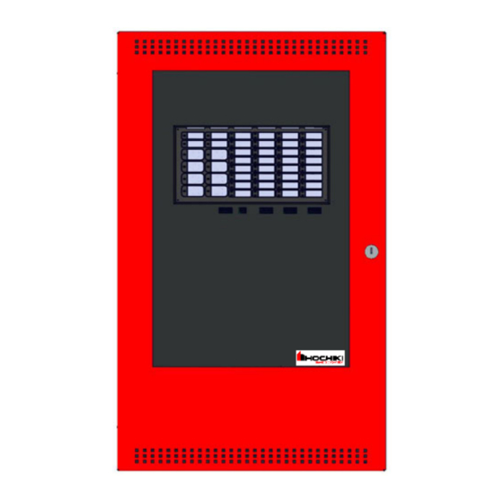
HCP 1000 SERIES
Microprocessor Based - Fire Alarm Control Panel
INSTALLATION and OPERATION MANUAL
©2017 by Hochiki America Corporation
Printed August 2017
LT-600HOC Rev.8
Table of
Contents
Previous
Page
Next
Page
1
2
3
4
5
Advertisement
Table of Contents
Need help?
Do you have a question about the HCP 1000 Series and is the answer not in the manual?
Ask a question
Questions and answers
Related Manuals for Hochiki HCP 1000 Series
Control Panel Hochiki HCP 1000 Series Installation And Operation Manual
Microprocessor based - fire alarm control panel (54 pages)
Control Panel Hochiki HRA-1000 SERIES Wiring And Installation Instruction
Remote multiplex annunciator panels (6 pages)
Control Panel Hochiki HCP-1008EDS Installation And Operation Manual
Microprocessor based-fire alarm control panel (80 pages)
Control Panel Hochiki HCP-1008E Installation And Operation Manual
Microprocessor based - fire alarm control panel (54 pages)
Control Panel Hochiki HCVX Installation And Operation Manual
Fire control panel (108 pages)
Control Panel Hochiki FP AP-1AS User Manual
Single/two loop control panel range (12 pages)
Control Panel Hochiki FIREvac User Manual
Voice alarm control panel (3 pages)
This manual is also suitable for:
Hcp-1008eds
Table of Contents
Print
Rename the bookmark
Delete bookmark?
Delete from my manuals?
Login
Sign In
OR
Sign in with Facebook
Sign in with Google
Upload manual
Upload from disk
Upload from URL


Need help?
Do you have a question about the HCP 1000 Series and is the answer not in the manual?
Questions and answers