Table of Contents
Advertisement
Quick Links
Technical
Information
TI 12E01B30-01EN
CONTENTS
Introduction .............................................................................................................2
1
Dimensions ...................................................................................................3
1.1
TB820D Dimensions ............................................................................................ 3
1.2
TB830D Dimensions ............................................................................................ 6
2.
Installation .................................................................................................... 16
3.
Piping .......................................................................................................... 17
3.1
TB820D (-NN, -A5) Piping .................................................................................. 17
3.1.1
3.1.2
3.2
TB830D (-NN, -A5) Piping .................................................................................. 32
3.2.1
3.2.2
4.
Wiring .......................................................................................................... 35
4.1
TB820D wiring .................................................................................................... 35
4.1.1
4.1.2
4.1.3
4.1.4
4.1.5
4.2
TB830D Wiring.................................................................................................... 44
4.2.1
4.2.2
4.2.3
4.2.4
4.2.5
5
Zero Turbidity Filter ................................................................................... 54
6
Operation .................................................................................................... 55
6.1
TB820D Supplying a Sample and Adjusting the Flow Rate .......................... 55
6.2
TB830D Preparation for Operation .................................................................. 56
7.
Automatic cleaning/Automatic zero calibration Sequence .................. 58
7.1
TB820D Sequence ............................................................................................. 58
7.2
TB830D Sequence ............................................................................................. 60
Revision Information ........................................................................................... 62
FLEXA, FLXA and SENCOM are trademarks or registered trademarks of Yokogawa Electric Corporation.
All other company and product names mentioned in this user's manual are trademarks or registered trademarks of their respective companies.
We do not use TM or ® mark to indicate those trademarks or registered trademarks in this user's manual.
TB820D, TB830D
Sampling System Selection
Manual
Head tank and Piping Parts ................................................................ 27
System without a Head Tank .............................................................. 31
Piping type .......................................................................................... 33
Head tank ............................................................................................ 34
SENCOM cable for turbidity and chlorine (A) ..................................... 39
Power cable for FLXA402T (B) ........................................................... 39
Power supply cable (C) ....................................................................... 39
Wiring with PG400 .............................................................................. 40
When Relay box for solenoid valve is included .................................. 40
SENCOM cable for Turbidity/Chlorine (A) .......................................... 47
FLXA402T power supply cable (B) ..................................................... 47
Power supply cable (E) ....................................................................... 47
TI 12E01B30-01EN
©Copyright Oct. 2022
3rd Edition Mar. 2023
Advertisement
Table of Contents

Subscribe to Our Youtube Channel
Related Manuals for YOKOGAWA TB820D


Summary of Contents for YOKOGAWA TB820D
-
Page 1: Table Of Contents
TB830D Sequence ..................... 60 Revision Information ................... 62 FLEXA, FLXA and SENCOM are trademarks or registered trademarks of Yokogawa Electric Corporation. All other company and product names mentioned in this user’s manual are trademarks or registered trademarks of their respective companies. -
Page 2: Introduction
Introduction This manual describes how to select a sampling system when the analyzer combined with the “TB820D Right Angle Scattered Light Turbidity Detector” and “TB830D Surface Scattering Light Turbidity Detector” does not have an assemble stanchion. If you specify without a sampling device (Suffix code -NN, -A5), you have to select and build system components such as a head tank, solenoid valve, and manual valve. -
Page 3: Dimensions
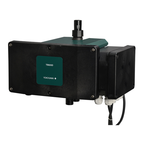
TB820D and TB830D Sampling System Selection Manual Dimensions TB820D Dimensions Top cover Detection unit Flow cell Smart unit Front cover Smart unit cover sample outlet Fuse Drain sample inlet Figure 1 TB820D part name TI 12E01B30-01EN Nov.22,2012-00... - Page 4 TB820D and TB830D Sampling System Selection Manual Unit: mm For wall mounting (4-M5 screws) sample outlet Rc1/2 or 1/2NPT Cleaning controller Ultrasonic oscillator Drain sample inlet (for oscillator) wiring port Rc1/2 or 1/2NPT Rc1/2 or 1/2NPT or more or more...
- Page 5 TB820D and TB830D Sampling System Selection Manual Installation Dimensions Install the TB820D’s detector unit in pipes or walls using their special mounting brackets, respectively. Note that these mounting brackets are supplied only when specified. Pipe Mounting (Option Code “/U”) For information on the converter, read FLXA402T IM.
-
Page 6: Tb830D Dimensions
TB820D and TB830D Sampling System Selection Manual TB830D Dimensions ● Without sampling system (-NN, -A5) Unit: mm (22) 4-ø4.2 hole 4-ø6.2 hole Figure 6 TB830D-NN, -A5 Dimensions l Maintenance space Maintenance space Maintenance space Unit: mm 250 or more 250 or more... - Page 7 TB820D and TB830D Sampling System Selection Manual l Pipe mounting hardware (/U) for -NN, -A5 Without sampling system Unit: mm (22) (215) Pipe 50A (or 2B) 4-M5 U-Bolt 4-ø10 Panel mounting hardware: /U (140) Figure 8 Pipe mounting hardware (/U) for -NN, -A5...
- Page 8 TB820D and TB830D Sampling System Selection Manual Other Dimensions l Terminal box A Unit: mm Terminal box A is supplied when “/ARS” option code is specified. Terminal box A can be connected to the pipe when “/C□” option code is specified.
- Page 9 TB820D and TB830D Sampling System Selection Manual l Terminal box B Unit: mm Terminal box B is supplied with the product in the following cases. • When both Sampling system “-NN” and Option “/C□” (Conduit adapter) are specified, but “/ ARS”...
- Page 10 TB820D and TB830D Sampling System Selection Manual l Installation of rack or wall mounting hardware (/R) on the terminal box B Unit: mm 132.5 Panel mounting 2-ø10 2-ø5.5 hardware: /R 2-M4 Figure 15 Installation of rack or wall mounting hardware (/R) on the terminal box B l Relay box A relay box is supplied with the product when “-A2”, “-A3”, or “-A5”...
- Page 11 TB820D and TB830D Sampling System Selection Manual l Installation of pipe mounting hardware (/U) on the relay box Unit: mm (52) Pipe 50A 4-M6 (or 2B) U-Bolt 2-ø9 Panel mounting (22) hardware: /U Panel mounting hardware: /U Figure 17 Installation of pipe mounting hardware (/U) on the relay box...
- Page 12 TB820D and TB830D Sampling System Selection Manual l PG400 dimensions and Mounting PG400 will be attached if you choose TB820D-U1. Unit: mm 4-M6 depth 8 For power supply For Oscillator cable (not used) Figure 20 Diagram of PG400 ● PG400 conduit Adapter (Option code: /CB, /CD, /CF)
- Page 13 TB820D and TB830D Sampling System Selection Manual (Note) The universal mounting kit (/UM) contains the pipe and wall mounting hardware (/U) and the panel mounting hardware (/PM). ● PG400 panel mounting hardware (Option code: /PM, /UM) Unit: mm 2-M5 length 35...
- Page 14 TB820D and TB830D Sampling System Selection Manual Note: The wall on which the analyzer is mounted should be strong enough to bear the weight of more than 8 kg. ● PG400 wall mounting hardware (Option code: /U, /UM) Unit: mm 4-M6 * For wall mounting 3-ø10 holes...
- Page 15 TB820D and TB830D Sampling System Selection Manual Note: The wall on which the analyzer is mounted should be strong enough to bear the weight of more than 8 kg. ● PG400 pipe mounting hardware (Option code: /U, /UM) Unit: mm...
-
Page 16: Installation
TB820D and TB830D Sampling System Selection Manual Installation The TB820 and TB830D should be installed in a location: • In a building or a cabinet where no direct sunlight or rainwater can get inside. Direct sunlight may cause an abnormal rise in the temperature inside the instrument and discoloration or deterioration of resin parts. -
Page 17: Piping
NV1: Keep a very small amount of water flowing at all times to prevent contamination of the zero filter and prevent freezing in winter. Atmospheric air open on the outlet side of NV3 Figure 28 Piping diagram for TB820D /D1 without Automatic clean/ Without Automatic zero calibration TI 12E01B30-01EN... - Page 18 NV1: Keep a very small amount of water flowing at all times to prevent contamination of the zero filter and prevent freezing in winter. Figure 29 Piping diagram for TB820D /D1 with Automatic cleaning/ With Automatic zero calibration (1) Piping of the Sample Line to the Detector This piping is for introducing a sample into the measurement cell of the detector.
- Page 19 TB820D and TB830D Sampling System Selection Manual For the piping between the pressurized head tank and the detector, connect a valve to one end of the 3-way tee fitting and connect a 8 mm OD x 6 mm ID polyethylene tube and the corresponding fitting between the valve and the pressurized head tank.
- Page 20 An optional simple head tank with a vent to the atmosphere (option code “/D2”), shown in Figure 38, is available from Yokogawa. The piping diagram of the simple head tank is shown in Figure 30, Figure 31 and Figure 32. The installation of the piping for the simple head tank is described below.
- Page 21 Keep a very small amount of water flowing at all times to prevent contamination of the zero filter and prevent freezing in winter. Figure 31 Piping diagram for TB820D /D2 with automatic cleanig / without automatic zero calibration TI 12E01B30-01EN...
- Page 22 Keep a very small amount of water flowing at all times to prevent contamination of the zero filter and prevent freezing in winter. Figure 32 Piping diagram for TB820D /D2 with automatic cleaning / with automatic zero calibration [Installation and Piping of the Simple Head Tank] To the sample inlet of the detector, attach a 3-way (tee) or appropriate fitting corresponding to the inlet’s connection size (Rc1/2 or 1/2 NPT).
- Page 23 NV1: Keep a very small amount of water flowing at all times to prevent contamination of the zero filter and prevent freezing in winter. Figure 33 Piping diagram for TB820D /D3 without automatic cleaning / without automatic zero calibration TI 12E01B30-01EN...
- Page 24 ø22/ø15 Flexible mesh-reinforced tube ø26/ø19 Flexible mesh-reinforced tube ø33/ø25 Flexible mesh-reinforced tube Note: Regarding requirement of solenoid valve, see “3.1.1 Head tank and Piping Parts”. Figure 34 Piping diagram for TB820D /D3 with automatic cleaning / without automatic zero calibration TI 12E01B30-01EN...
- Page 25 TB820D and TB830D Sampling System Selection Manual ● Automatic cleaning, automatic zero calibration Note: Needle valves are required to adjust the small flow rate by changing the valve opening. Open head tank Zero turbidity filter 1μm BV4 to 7, 9, 10: Ball valve TB820D...
- Page 26 TB820D and TB830D Sampling System Selection Manual • To prevent suspended matter to accumulate in the measurement cell. • To dislodge air bubbles from the measurement cell and the measurement window surface. Depending on the piping method, a flow rate of 5 to 10 L/min is obtained at a head difference (H) of 1 m with piping with nominal diameter of 16A.
-
Page 27: Head Tank And Piping Parts
3.1.1 Head tank and Piping Parts Sample introduced into TB820D needs to be free from air bubbles by using a Head tank to stabilize the pressure in piping and the flow rate. Select a head tank that matches the turbidity value of the sample from the following table. - Page 28 TB820D and TB830D Sampling System Selection Manual Figure 37 Pressurized head tank mounting position Install the head tank higher than the detector by exceeding the dimensions shown in the Figure TI 12E01B30-01EN...
- Page 29 TB820D and TB830D Sampling System Selection Manual Simple head tank (/D2) To meet the requirement of the flow rate , provide a head tank that also works as a deaeration tank (constant-level tank) and connect the measured water supply to the head tank. The head tank needs to be installed at an adequate height so as to regulate the flow rate.
- Page 30 TB820D and TB830D Sampling System Selection Manual Open head tank (/D3) Unit: mm 4-ø6.2 holes (for fixing) Approx. Sample inlet Ø22/Ø15 PE tube coupling 2-Ø10 holes Approx. (for fixing) Head pipe drain VP20 Pipe Sample outlet Head tank sample inlet Ø22/Ø15 PE tube...
-
Page 31: System Without A Head Tank
TB820D and TB830D Sampling System Selection Manual 3.1.2 System without a Head Tank This is a simple system where a sample is taken from the process and directly introduced into the detector. This system configuration can be used when a sample contains a negligible amount of air bubbles or when the turbidity of a sample is high and the effect of air bubbles is nonsignificant. -
Page 32: Tb830D (-Nn, -A5) Piping
TB820D and TB830D Sampling System Selection Manual TB830D (-NN, -A5) Piping The figure shown is an image. Use this as a reference when configuring your system. -NN Piping <Tubing materials> Head tank Detector Ø8 / Ø6 Polyethylene tube Ø12 / Ø9 Polyethylene tube Ø22 / Ø15... -
Page 33: Piping Type
TB820D and TB830D Sampling System Selection Manual 3.2.1 Piping type (1) Sample piping If the flow rate of the sample is 1.5 to 2 L/min, the sample can be introduced to the detector as is. Connect the supplied ø33 × ø25 mm black soft vinyl chloride tube to the sample inlet. -
Page 34: Head Tank
TB820D and TB830D Sampling System Selection Manual 3.2.2 Head tank Sample introduced into TB830D needs to be free from air bubbles by using a Head tank to stabilize the pressure in piping and the flow rate. Use the head tank of the following table. -
Page 35: Wiring
Ethernet (-E) (-WR) (73)NC *1: Power terminal "G" on TB820D must be grounded (ground resistance: 100 ohm or less). In case of selecting -NN as Relay box for solenoid valve, power supply cable connects with L(101), N(102) and G(001) in TB820D. - Page 36 See ● Solenoid valve (SV1 to SV4). Figure 49 Wiring TB820D-□□-□□-A5 CAUTION Turn off power supply to TB820D before wiring. Power rating must comply with TB820D specifications. Power voltage must match with the one indicated on the name plate. TI 12E01B30-01EN...
- Page 37 ● Don’t lose the four screws of the front cover. When wiring TB820D, first remove the cover of the smart unit. Provide the wiring with the cover removed. The product is shipped with cable gland attached to the cable entry.
- Page 38 TB820D and TB830D Sampling System Selection Manual SENCOM cable for Turbidity and chlorine (A) Power supply cable (C) clamp Power cable for FLXA402T (B) Power cable for PG400 Cable for Relay box control (E) Smart unit Detection unit Oscillator cable...
-
Page 39: Sencom Cable For Turbidity And Chlorine (A)
● The external power supply switch or a circuit breaker must comply with a current rating of 5Aor IEC60947-1 or IEC60947-3 ● Yokogawa recommend installing the external power supply switch, circuit breaker and TB820D converter all in the same location. -
Page 40: Wiring With
Provide wiring of Oscillator cable and Power cable for PG400, by referring to Figure 48, Figure 49, or Figure 50. Connect the Cable for PG400 to Detection unit, not to Smart unit of TB820D. Connect the connector as shown on the left in Figure 52 and thread it through the clamp as shown on the right. - Page 41 TB820D and TB830D Sampling System Selection Manual Power cable for Smart unit (D) Dedicated cable is supplied with the product. Table 4 Power cable for Smart unit Cable color Relay Box terminal No. Smart Unit terminal No. Black (L) White (N) Red (G) Fasten the M3 screw (L, N) with the tightening torque of 0.6 N·m, M4 screw (G) with 1.4 N·m.
- Page 42 Conduit adapters and dedicated cable glands, which are used in place of the standard cable gland for cable entry holes, are supplied with the product. You can specify the conduit adapter by Option code for both TB820D and FLXA402T, however, be aware of the following.
- Page 43 Power supply The standard cable length between FLXA402T and TB820D is 1 m. You can change the cable length by specifying a code from Option code. The number of cable entry holes to be used are defined by the specification as below.
-
Page 44: Tb830D Wiring
TB820D and TB830D Sampling System Selection Manual TB830D Wiring SENCOM cable for Turbidity/Chlorine (A) Cable clamp Relay box dedicated I/F cable (D) (for A and B) FLXA402T power supply cable (B) Power supply cable (C) SENCOM cable for Power supply cable (C) - Page 45 TB820D and TB830D Sampling System Selection Manual Power supply cable Power supply cable(E) Power supply cable(E) FLXA402T power supply cable (B) SENCOM cable for Turbidity/Chlorine (A) TB830D Surface scattering turbidity detector FLXA402T Liquid Analyzer for Turbidity and Chlorine Terminal box A...
- Page 46 TB820D and TB830D Sampling System Selection Manual WARNING The wiring must meet the IP65 or higher. The four screws of the detector cover are tightended to 1.5 N·m. For sensor modules For IO module For COM module M3 screw Power cable...
-
Page 47: Sencom Cable For Turbidity/Chlorine (A)
TB820D and TB830D Sampling System Selection Manual TB830D power supply (C) Relay Box power cable (D) L (201) L (202) Ground terminal Power supply cable (C) L (201) L(202) Power supply cable Ground terminal G L (101) L (102) Ground terminal G... - Page 48 • Install an external switch or breaker on the power supply of TB830D. • Use external switches or breakers that conform to nominal 5A, IEC 60947-1 or IEC 60947-3. • Yokogawa recommends installing the external power supply switch, circuit breaker, and TB830D all in the same location.
- Page 49 TB820D and TB830D Sampling System Selection Manual Next diagram shows the position of each cable entry (lll) where you can attach conduit adapters for the conduit. • TB830D-..-NN-□N-NN-NN/ARS/C□ TB830D FLXA402T Terminal Power Power mA output/input supply 1st input mA output/input*3...
- Page 50 TB820D and TB830D Sampling System Selection Manual • TB830D-..-A5--NN... /C□ *4 TB830D FLXA402T Power mA output/input 1st input mA output/input*3 Contact outputs*3 2nd input*3 Contact outputs*3 Digital Communication*3 1,2,3,5,10,20 m Relay Power supply • TB830D-..-A5--NN... /ARS/C□ TB830D FLXA402T Power mA output/input...
-
Page 51: Without A Sampling System And With A Relay Box For Solenoid Valve
TB820D and TB830D Sampling System Selection Manual 4.2.5 Without a sampling system and with a Relay box for solenoid valve When the suffix code-A5 (without sampling system and with Relay box for solenoid valve) is specified, a Relay box is included. - Page 52 TB820D and TB830D Sampling System Selection Manual WARNING Never let the power cables of TB830D (Figure 63) touch the Cable for Relay box control (F), SENCOM cable for turbidity/chlorine (A), resulting in failure to comply with the safety requirements. WARNING Wire the wire so that it meets the IP65 or higher.
- Page 53 TB820D and TB830D Sampling System Selection Manual Relay Box power supply cable (D) This is an power supply cable that connects the Relay box to the Relay box when a Relay box is attached. Dedicated cables are included. Refer to Figure 62 and Figure 64 for wiring. Cables have no terminal names on them.
-
Page 54: Zero Turbidity Filter
TB820D and TB830D Sampling System Selection Manual Zero Turbidity Filter Unit: mm 4-M4 fixing screws ø115 ø121 Piping inlet & outlet Rc1/2 Vent plug Filter Part No. Filtering size K9411UA 1 μm K9726EF 0.2 μm Figure 65 Zero turbidity filter For TB820D Use 0.2 µm and 1 µm filter. -
Page 55: Operation
TB820D and TB830D Sampling System Selection Manual Operation TB820D Supplying a Sample and Adjusting the Flow Rate Supply a sample to the detector and adjust its flow rate. System Using an Open Head Tank (Option code /D3) (See Piping Diagram in Figure 40) Open the sample valve to supply a sample to the head tank. -
Page 56: Tb830D Preparation For Operation
TB820D and TB830D Sampling System Selection Manual TB830D Preparation for Operation n Leveling detector (flow rate Adjustment) The measurement surface is rippled. The measurement surface is rippled. Flow cell (a) Unmeasurable status Measurement surface is a mirror surface. Flow cell Thread A (b) Measurable status... - Page 57 TB820D and TB830D Sampling System Selection Manual n Supplying Sample and Adjustment flow rate Turn Off converter maintenance mode. Set the manual valve to the measurement state. Supply the specified flow rate (2-10 L/min) of the sample. Measure the displacement of the detector drain with a graduated cylinder, etc., and confirm that the displacement is within 1.5 L ±...
-
Page 58: Automatic Cleaning/Automatic Zero Calibration Sequence
TB820D and TB830D Sampling System Selection Manual Automatic cleaning/Automatic zero calibration Sequence TB820D Sequence The next diagrams show how the solenoid valve works during TB820D automatic cleaning / automatic zero calibration. During Automatic cleaning The parameters on valve working during automatic cleaning are as follows. - Page 59 After the calibration time elapses, SV3 closes, SV4 opens, and TB820D starts draining the zero water out of the flow cell. After the draining finishes, SV4 closes, SV1 opens, and TB820D starts feeding a sample into the flow cell. After the sample feeding when the Recovery time elapses, automatic zero calibration sequence ends and a measurement starts.
-
Page 60: Tb830D Sequence
TB820D and TB830D Sampling System Selection Manual TB830D Sequence Automatic cleaning (without automatic zero calibration) Status Meas. Cleaning Recovery Meas. OPEN SV2(Wash. water) CLOSE Flow/Calibration Cleaning Flow/Calibration Recovery Waiting time Waiting time OPEN SV4(Drain) CLOSE Drainage time Drainage time Figure 70... - Page 61 TB820D and TB830D Sampling System Selection Manual After the “Flow/Calibration Waiting time” elapses, SV2 (wash water) opens. Wash water (tap water) starts purging from two water ports on the side of the Flow cell to wash the side or edge of the Flow cell.
-
Page 62: Revision Information
TB820D and TB830D Sampling System Selection Manual Revision Information Title : TB820D and TB830D Sampling System Selection Manual Manual number : TI 12E01B30-01EN Mar. 2023/3rd Edition Changed explanation (page 9). Changed part number (page 53) and figures (page 32). Jan. 2023/2nd Edition Added TB830D Oct.
Need help?
Do you have a question about the TB820D and is the answer not in the manual?
Questions and answers