
Related Manuals for YOKOGAWA TB820D


Summary of Contents for YOKOGAWA TB820D
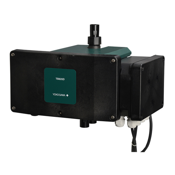
- Page 1 User’s Manual TB820D Right Angle Scattered Light Turbidity Detector IM 12E01B30-02EN IM 12E01B30-02EN 2nd Edition...
-
Page 2: Introduction
Thank you for purchasing TB820D Right Angle Scattered Light Turbidity Detector, FLXA402T Liquid Analyzer for Turbidity and Chlorine. This User’s Manual contains all essential information for the user to make full use of TB820D and FLXA402T. Please read the following respective documents before installing and using the instrument. - Page 3 • No part of the user’s manuals may be transferred or reproduced without prior written consent from YOKOGAWA. • YOKOGAWA reserves the right to make improvements in the user’s manuals and product at any time, without notice or obligation. • If you have any questions, or you find mistakes or omissions in the user’s manuals, please contact our sales representative or your local distributor.
-
Page 4: Table Of Contents
Toc-1 <CONTENTS> TB820D Right Angle Scattered Light Turbidity Detector IM 12E01B30-02EN 2nd Edition CONTENTS ◆ INTRODUCTION .....................i OVERVIEW ....................1-1 Measurement system and structure ............... 1-1 Part Name and Functions ................1-2 Specifications ....................1-2 Model and Codes ....................1-3 External Dimensions .................. - Page 5 Toc-2 <CONTENTS> 4.1.3 Meas. damping time constant, Maint. damping time constant ..4-3 4.1.4 Turbidity warning High/Low limit ............4-3 4.1.5 Air denoising setting ................4-3 Cal./Maint. Settings ................... 4-6 4.2.1 Turbidity value of check tool ............... 4-6 4.2.2 Zero shift value, Correction factor ............4-6 4.2.3 Stability check ..................
- Page 6 Toc-3 <CONTENTS> 7.10 Basic (reference) sensitivity calibration ............7-11 7.11 Calibration Error ....................7-11 MAINTENANCE ..................8-1 Washing the Flow cell ..................8-2 Washing the Head Tank ..................8-3 Checking and Replacing Desiccants .............. 8-4 Pipe Cleaning ....................8-4 Replacing the Zero Turbidity Filter Element ..........8-5 LED Replacement .....................
- Page 7 Blank Page...
-
Page 8: Overview
Sampling System Sample introduced into TB820D needs to be free from air bubbles by using a Head tank to stabilize the pressure in piping and the flow rate. Use the sampling system if necessary. -
Page 9: Part Name And Functions
Part Name and Functions TB820D Turbidity detector Top cover Detection unit Flow cell Smart unit Front cover Smart unit cover Sample water outlet Fuse Drain Sample water inlet Specifications See TB820D General Specification 12E01B30-01EN. IM 12E01B30-02EN 2nd Edition : June 09 , 2021-00... -
Page 10: Model And Codes
TB820D Right Angle Scattered Light Turbidity Detector Option Model Suffix code Description code TB820D ············································· ········· Right Angle Scattered Light Turbidity Detector Light ········· 660nm, Formazin, 0-0.2 NTU to 0-500 NTU source 860nm, Formazin, 0-0.2 FNU to 0-700 FNU Type ·········... -
Page 11: External Dimensions
When Sample is irradiated with light, the incident light is scattered by the turbidity particle. TB820D measures turbidity by using 660 nm or 860nm monochromatic light as the light source and detecting light scattered in the sample in the 90-degree direction. -
Page 12: Installation, Piping, And Wiring
• that provides adequate maintenance space and easy access for maintenance work; and, • where the drain is provided. Installation Dimensions Install the TB820D’s detector unit in pipes or walls using their special mounting brackets, respectively. Note that these mounting brackets are supplied only when specified. Pipe Mounting (Option Code “/U”) For information on the converter, read FLXA402T IM. -
Page 13: Wiring
Ethernet (-E) (-WR) (73)NO *1: Power terminal "G" on TB820D must be grounded (ground resistance: 100 ohm or less). In case of selecting -NN as Relay box for solenoid valve, power supply cable connects with L(101), N(102) and G(001) in TB820D. - Page 14 Figure 2.2 Wiring TB820D-□□-□□-A5 CAUTION Turn off power supply to TB820D before wiring. Power rating must comply with TB820D specifications. Power voltage must match with the one indicated on the name plate. IM 12B01B30-02EN 2nd Edition : June 09 , 2021-00...
- Page 15 ● Don’t lose the four screws of the front cover. When wiring TB820D, first remove the cover of the smart unit. Provide the wiring with the cover removed. The product is shipped with cable gland attached to the cable entry.
- Page 16 Power cable for PG400 Cable for Relay box control (E) Smart unit Detection unit Oscillator cable View from the bottom Figure 2.3 Wiring TB820D Smart unit side For sensor modules For IO module For COM module M3 screw Power cable for FLXA402T (B)
-
Page 17: Sencom Cable For Turbidity And Chlorine (A)
● The external power supply switch or a circuit breaker must comply with a current rating of 5Aor IEC60947-1 or IEC60947-3 ● Yokogawa recommend installing the external power supply switch, circuit breaker and TB820D converter all in the same location. -
Page 18: Wiring With
Provide wiring of Oscillator cable and Power cable for PG400, by referring to Figure 2.1 or Figure 2.2-Figure 2.3. Connect the Cable for PG400 to Detection unit, not to Smart unit of TB820D. Connect the connector as shown on the left in Figure 2.5 and thread it through the clamp as shown on the right. - Page 19 Cable for SV (F) Solenoid valve and solenoid valve cable are provided by customers. See Table 2.4 and Table 2.7 for the required specifications. Yokogawa also provides these products. Solenoid valve is not supplied with Relay box for solenoid valve. Purchase separately an appropriate solenoid valve.
-
Page 20: Piping
Calibration and maintenance such as measurement cell cleaning are efficiently performed by valve operation. An optional Open head tank (option code “/D3”), shown in Figure 2.20, is available from Yokogawa. Unit: mm 4-ø6.2 holes (for fixing) Approx. - Page 21 2-10 <2. INSTALLATION, PIPING, AND WIRING> Head Tank Flow Control Valve Sample Water Effluent Sample Water Outlet Sample Water Drain Detector Sample Water Drain Drain Valve Valve Sample Water Sample Water Drain Port Drain Inlet Sample Water Drain Valve Supply Valve Zero Water Drain Water...
- Page 22 2-11 <2. INSTALLATION, PIPING, AND WIRING> (2) Piping of the Sample Line from the Detector This piping is for draining a sample from the measurement cell of the detector during measurement. The sample outlet of the detector is Rc1/2 (or 1/2 NPT female) thread. Install a fitting corresponding to the thread and connect a hose/tube with sufficient diameter that provides adequate flow of sample, to route the sample from the detector to a drain pipe.
-
Page 23: A System Using A Simple Head Tank (/D2)
An optional simple head tank with a vent to the atmosphere (option code “/D2”), shown in Figure 2.22, is available from Yokogawa. The piping diagram of the simple head tank is shown in Figure 2.23. The installation of and the piping for the simple head tank are described below. - Page 24 2-13 <2. INSTALLATION, PIPING, AND WIRING> [Installation and Piping of the Simple Head Tank] To the sample inlet of the detector, attach a 3-way (tee) or appropriate fitting corresponding to the inlet’s connection size (Rc1/2 or 1/2 NPT). This allows switching of the sample flow and the zero water flow.
-
Page 25: System Using A Pressurized Head Tank (/D1)
In that case, consider the use of an open head tank. An optional pressurized head tank for low turbidity measurement (option code “/D1”), shown in Figure 2.24, is available from Yokogawa. Unit: mm Pressure gauge... - Page 26 2-15 <2. INSTALLATION, PIPING, AND WIRING> The piping diagram of a system including the pressurized head tank is shown in Figure 2.24. Pressure Gauge Bypass Valve Flow Control Valve Sample Effluent Sample Pressurized Outlet Head Tank Drain Drain Detector Sample Sample Sample Drain Port...
- Page 27 2-16 <2. INSTALLATION, PIPING, AND WIRING> (2) Piping of the Sample Line from the Detector This piping is for draining a sample form the measurement cell of the detector during measurement. As shown in the piping diagram in Figure 2.24, connect a needle valve to the sample outlet of the detector.
-
Page 28: System Without A Head Tank
In that case, consider the use of an open head tank. The piping diagram of a system without a head tank is shown in Figure 2.25. Flow Control Valve Sample Effluent Sample Outlet TB820D Process Piping Drain Detector Sample Sample Sample Water... - Page 29 2-18 <2. INSTALLATION, PIPING, AND WIRING> To prevent clogging or stagnation of air bubbles in the pipe line, install the pipes so that no bends or stagnation occurs. (2) Piping of the Sample Line from the Detector This piping is for draining a sample from the measurement cell of the detector during measurement.
-
Page 30: Preparation For Operation
<3. PREPARATION for OPERATION> PREPARATION for OPERATION Operation mode Two types as follows are available. Measurement mode Steady-state operation takes place. Maintenance mode Perform maintenance in this mode. Be sure to turn to this mode before starting calibration or maintenance. To switch to Maintenance mode, Main screen >... -
Page 31: Filling Zero Water And Test Operation
3: Setting Auto wash/Auto calibration Configure sequence operation by setting up the converter. see “4.5 Auto Wash/ Calibration setting” Calibration Operate TB820D for about one hour before calibration. Refer to “7. CALIBRATION” for calibration requirements. IM 12E01B30-02EN 2nd Edition : June 09 , 2021-00... -
Page 32: Supplying A Sample And Adjusting The Flow Rate
<3. PREPARATION for OPERATION> Supplying a Sample and Adjusting the Flow Rate Supply a sample to the detector and adjust its flow rate. System Using an Open Head Tank (Option code /D3) (See Piping Diagram in Figure 2.20) (1) Open the sample valve to supply a sample to the head tank. (2) Completely open the sample supply valve to allow the sample to flow into the detector. -
Page 33: Adjusting Ultrasonic Power
<3. PREPARATION for OPERATION> Adjusting ultrasonic power When “-U1” for the Oscillator for ultrasonic cleaning is specified, adjust the ultrasonic power. Be sure to fill the flow cell with a sample when adjusting the ultrasonic power. First, turn on the ultrasonic power from the maintenance menu of FLXA402T. -
Page 34: Setting Parameters
<4. SETTING PARAMETERS> SETTING PARAMETERS This chapter describes all Sensor setting and Auto wash/Cal setting as a part of converter menu. About other setting parameters of the converter menu, read FLXA402T Operation of Converter. To go to Sensor setting menu, refer to 5.5 Setting. To go to the converter menu, refer to FLXA402T Operation of Converter 12A01G01-03EN. - Page 35 <4. SETTING PARAMETERS> Menu Parameter Default Reference Diagnosis setting Light source diagnosis Enable 4.3.1 Dried condition diagnosis Enable Light source operating days Enable Wiper operating days Enable Communication Sensor connection address setting Depend on the configured unit of turbidity Value is preset factory default. After initialization, set each value to default.
-
Page 36: Measure Setting
<4. SETTING PARAMETERS> Measure setting 4.1.1 Negative value non output Select whether to display and output negative value or fix the value as “0” when the measurement results negative. 4.1.2 Turbidity unit select Select turbidity unit, mg/L, TU, NTU, FTU, FNU, or user defined unit. If you select a user defined unit, the unit is displayed in text. - Page 37 <4. SETTING PARAMETERS> [How It Functions] To suppress a sudden fluctuation due to air bubbles or dust, the TB820D: (1) checks a turbidity signal before averaging; (2) calculates the difference between the current signal and the previous signal; (3) compares the difference with the Air noise detection value;...
- Page 38 <4. SETTING PARAMETERS> (No turbidity signal is taken during the process) Air Bubbles Detected Function restarts A > Air noise detection value A < Air noise detection value Denoising release Air denoising hold time time In Process Turbidity Signal Intake Cycle Time A: Difference between the current signal and the previous signal F6-12E.ai...
-
Page 39: Cal./Maint. Settings
<4. SETTING PARAMETERS> Cal./Maint. Settings 4.2.1 Turbidity value of check tool Displays the value on the turbidity check tool to measure the slope. The value is set at the factory. 4.2.2 Zero shift value, Correction factor These parameters are related to zero shift correction and sensitivity correction in the calibration menu. -
Page 40: Calibration Setting Others
<4. SETTING PARAMETERS> 4.2.6 Calibration setting others Zero, slope, Sens.factor is changed manually. Do not change those setting except for resetting value. Go to sensor detail screen to check the setting as reference. Diagnosis setting 4.3.1 Light source diagnosis Select Light source diagnosis On/Off. See 5.3 for details. 4.3.2 Dried condition diagnosis Select Dried condition diagnosis On/Off. -
Page 41: Auto Wash/Calibration Setting
<4. SETTING PARAMETERS> Auto Wash/Calibration setting 4.5.1 Auto sequence for wash/cal. Enable this function to use Auto wash/calibration. If this function is disabled, Auto wash/ calibration is never implemented even if other setting is active. 4.5.2 Start date As the first time Auto wash/calibration, enter a future date/time but not the current one. If you want to perform the next and subsequent Auto wash/calibration automatically, turn ON Auto update of start date. -
Page 42: Flxa402T Sensor Menu
<5. FLXA402T sensor menu> FLXA402T sensor menu Start up> Main screen to Converter menu Measurement value Icon appears here to show the status. Nothing appears at a measurement mode to Calibration menu to Sensor menu Maintenance mode ON/OFF On Main screen the shortcut menus Maintenance mode dialog To go to Sensor menu, Start up>... -
Page 43: Wash
“Detail” > to check details (setup, sensor diagnosis, calibration, and module production number). In case of trouble, when you contact Yokogawa service, please inform us of the module and FLXA402T software revision displayed on the Detail under converter menu and sensor menu and... - Page 44 Sensor menu flow chart Measurement value Turbidity Shows the turbidity on Main screen. Current value Shows input current value of Transmitted, Scattered light, Light source. TB820D does not support “Transmitted”, which displays “----”. IM 12E01B30-02EN 2nd Edition : June 09 , 2021-00...
- Page 45 <5. FLXA402T sensor menu> Zero, Slope, Corr. factor, Zero shift value It is recommended that you note the values of these items prior to performing calibration. When calibration is executed, the data is overwritten. Lightening IF Shows a driving current value of the light source. Sensor wellness Light source diagnosis The result shows how much the Light source condition has changed since the factory preset.
-
Page 46: Reset Op. Time
<5. FLXA402T sensor menu> TB detector Displays Serial number (Serial No.) of a connected Turbidity detection unit, software version (Software Rev.), Model code (Model code), internal serial number of CPT board, LED board and analog board (Internal SN.(CPT), Internal SN.(LED), Internal SN.(Analog) ). Converter log, Sensor log Same display as on the converter “Detail”. -
Page 47: Maintenance
<5. FLXA402T sensor menu> Sensor setting Set sensors. See 4.1 for the setting. Initialization Initialize sensor parameters. In the box of File name, name of defined sensor config. file to load is displayed, after sensors connected are automatically detected. You cannot change the file name. If you tap “Execute”, the loading starts. -
Page 48: Operation
The turbidity measurement is not affected by temporary suspension of sample water supply, but long-term suspension may interfere with the accuracy of the instrument. Since the TB820D cannot detect whether the sample water supply is stopped or not, periodical check of the sample line is needed. - Page 49 Blank Page...
-
Page 50: Calibration
< 7. Calibration > CALIBRATION This chapter describes types of calibration enabled with TB820D. Periodical calibration and an optimization of calibration parameters for Zero or Slope ensure accurate measurement. Zero shift or the sensitivity correction can also correct the standard and grab sample sensitivity. Clean the Flow cell before calibration. -
Page 51: Turbidity Calculation And Calibration Menu
< 7. Calibration > Turbidity calculation and calibration menu Zero, Slope are adjusted based on a standard solution as a reference. (Equation 7.1) If the turbidity measured by the instrument may differ from the one measured manually in a lab due to the difference of properties of the water sample and of turbidity measurement methods, the instrument can be adjusted so that it reads the same value as the one measured in a lab by performing the zero shift correction or sensitivity correction. -
Page 52: Turbidity Standards
Zero Standard Zero Turbidity Standard Solution Filtered tap water is used as a zero turbidity standard solution for TB820D turbidity detector. For zero calibration, tap water should be filtered in two steps: first through a 1 µm filter and then through a 0.2 µm filter. - Page 53 Therefore, the same check tool cannot be purchased again. If it is lost, contact Yokogawa. We may provide another check tool prepared in advance. IM 12E01B30-02EN 2nd Edition : June 09 , 2021-00...
- Page 54 < 7. Calibration > <How to clean the check tool> Clean the dust and dirt on the surface of the check tool. (1) Cleaning with the attached silicone cloth or washing If the surface is dusty, use the included silicone cloth to gently wipe it off and remove the dust.
- Page 55 < 7. Calibration > Preparing a Formazin Standard Stock Solution Reagents Required • Hydrazine sulfate, (NH ·H • Hexamethylene tetramine, (CH )6·N Equipment Required • Measuring flask, 2 x 100 ml • Measuring flask, 1000 ml • Volumetric pipette, 50 ml •...
-
Page 56: Zero Calibration
< 7. Calibration > Zero Calibration Supply Zero water or turn off the light source to perform Zero calibration. See ■ Zero standard (7.2) to confirm about zero water. [How to perform Zero calibration] 1 Turn on the maintenance mode. 2 Clean the Flow cell. -
Page 57: Slope Calibration (Check Tool)
< 7. Calibration > Slope calibration (Check tool) When you calibrate both zero point and slope, first calibrate the zero point and then the slope. See ■”Check Tool” to confirm about check tool. [How to perform Slope calibration-Check tool] 1 Turn on the maintenance mode. Remove the top cover from the top of the detector. Loosen the four screws fixing the clear cover and remove the clear cover. -
Page 58: Auto Zero Calibration
< 7. Calibration > Auto zero calibration Auto wash and auto calibration run one time. Execute this operation in a measurement mode. Maintenance mode cannot carry out this operation. This operation does not affect any automatic sequence schedule. Zero shift correction Perform this calibration when you need to adjust the Zero value after both Zero and Slope calibration are conducted correctly. -
Page 59: Points Correction
7-10 < 7. Calibration > 2 points correction The Zero point and Sensitivity correction factor are adjusted. Use two arbitrary known turbidity solution. Take two measurements and record the low concentration as low point, the high concentration as high point. Be sure to take low point first, then do the measurement of the high point. -
Page 60: Basic (Reference) Sensitivity Calibration
7-11 < 7. Calibration > 7.10 Basic (reference) sensitivity calibration Sensitivity factor(S0) is updated The slope is 100 %. Be sure to perform this calibration after implementing the Zero calibration. No error check is conducted at the calibration, therefore, perform calibration properly. For information on preparation of calibration solution, see “■... - Page 61 Blank Page...
-
Page 62: Maintenance
<8. MAINTENANCE> MAINTENANCE This chapter describes the inspection and maintenance required to keep the instrument in good operating condition. Inspection/Maintenance Items and Intervals The main inspection/maintenance items and their recommended intervals to keep the instrument in good operating condition, are provided in Table 8.1. Since the frequency of inspection/ maintenance depends on the operating conditions, use the recommended intervals shown in Table 8.1 as a reference and perform inspection/maintenance at appropriate intervals. -
Page 63: Washing The Flow Cell
<8. MAINTENANCE> Washing the Flow cell The top cover (rubber cover) and the clear cover can be removed to clean the inside of the Flow cell and the surface of the window glass. If dirt remains, you can remove the sample outlet pipe and the upper part of the Flow cell to clean every corner in the Flow cell and the window glass. -
Page 64: Washing The Head Tank
(1) Turn on the maintenance mode. (2) Close the sample supply valve. (3) Draining water from the head tank and washing it. The following describes how to wash two optional head tanks provided by Yokogawa. [Pressurized head tank] 1. Close the sample valve. -
Page 65: Checking And Replacing Desiccants
<8. MAINTENANCE> Checking and Replacing Desiccants Inspect the condition of desiccant once every 6 months and replace it if necessary. Regardless of the result of the inspection, replace the desiccant once a year. If the humidity in the detector (the light source unit and the receiver) is high when a sample with low temperature runs into the Flow cell, condensation may form on the window glass. -
Page 66: Replacing The Zero Turbidity Filter Element
<8. MAINTENANCE> Replacing the Zero Turbidity Filter Element The zero turbidity filter element should be replaced at regular intervals. (1) Make sure that the zero water supply valve and the zero water drain valve after the zero turbidity filter are closed. (2) Close the tap water valve before the zero turbidity filter to stop supplying tap water. -
Page 67: Led Replacement
LED Replacement CAUTION • Turn off the power of TB820D before replacing the LED. • LED may be damaged by static electricity. When replacing the LED be sure to take measures against static electricity, such as using a grounded wristband. - Page 68 <8. MAINTENANCE> Front cover LED bracket LED bracket Figure 8.5 LED Replacement Strap Pinch the strap and remove the lock lever. Pull out the connector. Figure 8.6 Disconnecting cables IM 12B01B30-02EN 2nd Edition : June 09 , 2021-00...
-
Page 69: Fuse Replacement
Fuse Replacement If the fuse blows, replace the fuse. There is one fuse in the FLXA402T, one in the TB820D, and two in the Relay box (when Suffix code -A5 is selected). Read IM 12A01G01-02JA for fuse replacement of FLXA402T. - Page 70 Arrange the fuse as below. Table 8.5 Fuse Part No. Name Description A1633EF FUSE 1 fuse for TB820D A1624EF FUSE 1 fuse for Relay box (*) 2 fuses are required for Relay box. IM 12B01B30-02EN 2nd Edition : June 09 , 2021-00...
-
Page 71: Window Glass Replacement
8-10 <8. MAINTENANCE> Window glass replacement For TB820D you can replace the window glass of the Flow cell. There are three window glasses in the Flow cell (see Figures 8.2, 8.10). Refer to Section 8.9 when replacing each Flow cell. - Page 72 2. Wipe the inside of the Flow cell with a soft cloth. 3. In order to prevent the water remaining inside the liquid tank from dripping inside the TB820D main body, attach the red caps to the sample inlet pipe and the sample drainage pipe. (Figure 8.13).
- Page 73 (4) Removal of the oscillator cable (when the suffix code -U1 is selected) Loosen the six (6) screws and open the front cover of the TB820D. Remove the oscillator cable at the connector as shown in the figure. (See Figure 8.14) Remove the oscillator cable at the connector.
- Page 74 (2) Oscillator cable installation (Suffix code -U1 selected) Connect the oscillator cable to the connector and secure it with a clip as shown in the figure. Close the front cover of the TB820D and tighten the six (6) screws. (See Figure 8.17) Connect the oscillator cable Secure the oscillator cable at the connector.
-
Page 75: Flow Cell Replacement
Piping cap Flow cell replacement You can replace Flow cell of TB820D. Arrange a replacement for Flow cell according to Table 8.8. Figure 8.18 shows an example of Flow cell for replacement. A window glass is attached to the replacement Flow cell in advance. If the suffix code -U1 is selected, the oscillator is attached to the Flow cell window. -
Page 76: Troubleshooting
TB820D Error List Alarm Name Explanation Remedy NE107 NE107 Number Default Changed X500 EEPROM error The TB820D has become Disable defective. Contact Yokogawa service. X501 User param. read error The TB820D has become Disable defective. Contact Yokogawa service. X502 Factory param. read... - Page 77 Note : X of Alarm Number denotes Channel of the measurement electrode unit. 1: sensor connection number 1-1 5: sensor connection number 2-1 6: sensor connection number 2-2 (not required on the first FD) Table 9.2 TB820D Analyzer Error Message List (Wash) Alarm Name Explanation Remedy...
-
Page 78: When No Error Indication Appears
● Check the light source is lit on. does not vary. ● Communication between Detector ● Check the cable connection between and Liquid analyzer is abnormal. FLXA402T Analyzer and TB820D detector. IM 12E01B30-02EN 2nd Edition : June 09 , 2021-00... - Page 79 Blank Page...
-
Page 80: Appendix
App.-1 <APPENDIX> Appendix Automatic wash/Automatic calibration Sequence The next diagrams show how the solenoid valve works during TB820D Automatic wash / Automatic calibration. During Automatic wash The parameters on Valve working during Automatic wash are as follows. ● Drainage time ●... - Page 81 After the calibration time elapses, SV3 closes, SV4 opens, and TB820D starts draining the zero water out of the flow cell. After the draining finishes, SV4 closes, SV1 opens, and TB820D starts feeding a sample into the flow cell. After the sample feeding when the Recovery time elapses, Automatic calibration sequence ends and a measurement starts.
- Page 82 Gasket (65 mm × 65 mm) K8003NU Gasket Assy (One gasket each (K8003NQ, K8003NS), 2 O-rings (large), 1 O-ring (small) A1633EF Fuse CMPL 12E01B30-01EN All Rights Reserved. Copyright © 2021 Yokogawa Electric Corporation. Subject to change without notice. 1st Edition: May 2021 (YK)
- Page 83 Relay box (for -A5) Item Part No. Description A1624EF Fuse CMPL 12E01B30-01EN 1st Edition: May 2021 (YK)
- Page 84 K9411UA ZERO TURBIDITY FILTER ASSEMBLY (1 micron filter) K9726EF ZERO TURBIDITY FILTER ASSEMBLY (0.2 micron filter) Item Part No. Description K9008ZD Filter Element (1 micron) K9726EH Filter Element (0.2 micron) K9411UB Case K9008ZE Plate K9411UD O-Ring K9411UC O-Ring K9411UE O-Ring K9411UF Head CMPL 12E01B30-01EN 1st Edition: May 2021 (YK)
-
Page 86: Revision Information
Revision Information Title: TB820D Right Angle Scattered Light Turbidity Detector Manual No.: IM 12E01B30-02EN June 2021/2nd Edition Added a Model and Suffix code (page 1-3) Corrected errors (pages 1-3, 2-7) Added a section/description (page 3-4, 7-4, 8-4) Mar. 2021/1st Edition Newly published. - Page 87 Blank Page...
Need help?
Do you have a question about the TB820D and is the answer not in the manual?
Questions and answers