Table of Contents
Advertisement
Quick Links
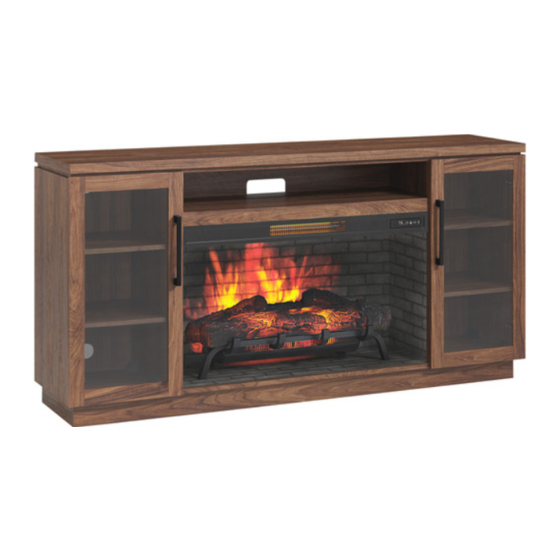
66" Fireplace Media
Console with 36"
Traditional Infrared
Electric KD Insert
ASSEMBLY, CARE & USE INSTRUCTIONS
MODEL # 1372KDI-36-268
Date Purchased _______________________
Questions, problems, missing parts? Before returning to your retailer, call our customer service
department at 1-704-461-2414 8:30 a.m. - 5 p.m., EST, Monday - Friday.
www.greentouchhome.com
1
Français p. 20
Español p. 39
Advertisement
Table of Contents

Subscribe to Our Youtube Channel
Related Manuals for Greentouch 1372KDI-36-268


Summary of Contents for Greentouch 1372KDI-36-268
- Page 1 Traditional Infrared Electric KD Insert ASSEMBLY, CARE & USE INSTRUCTIONS MODEL # 1372KDI-36-268 Date Purchased _______________________ Questions, problems, missing parts? Before returning to your retailer, call our customer service department at 1-704-461-2414 8:30 a.m. - 5 p.m., EST, Monday - Friday.
- Page 2 PACKAGE CONTENTS PART DESCRIPTION QUANTITY PART DESCRIPTION QUANTITY Back Panel Center Shelf Fireplace Brick Wall Left Middle Wall Fire Log Right Middle Wall Fireplace Grate Left Outer Wall Remote Control (Battery Inside) Right Outer Wall Baffle Left Door Fireplace Glass Front Right Door Base Shelf...
-
Page 3: Table Of Contents
HARDWARE CONTENTS (NOT SHOWN ACTUAL SIZE) PART DESCRIPTION QUANTITY PART DESCRIPTION QUANTITY Bolt Hinge Wooden Dowel Hinge Screw Back panel mounting Door Pull hardware Touch-up Pen L-Bracket Screw Shelf Pin SAFETY INFORMATION Please read and understand this entire manual before •... - Page 4 SAFETY INFORMATION (CONTINUED) Modifications not approved by the party responsible • DO NOT route cord under furniture or appliances. for compliance could void user’s authority to operate Arrange cord away from traffic areas and where it the equipment. will not be tripped over. •...
- Page 5 SAFETY INFORMATION (CONTINUED) • To avoid electric shock, fire, or injury, review the • To disconnect this appliance, turn controls to the assembly instruction to confirm that the appropriate OFF position, then remove plug from outlet. • ONLY connect to properly grounded outlets. critical components and accessories are being used with the furnishing.
- Page 6 SAFETY INFORMATION (CONTINUED) Electrical Connection Grounding Instructions • A 15-Amp, 120-volt, 60 Hz circuit with a properly • This heater is for use on 120 volt. The cord has a grounded outlet is required. Preferably, the fireplace plug as shown below. See illustration or grounding will be on a dedicated circuit as other appliances instruction.
-
Page 7: Aa Bolt
PREPARATION Before beginning assembly of product, make sure Estimated Assembly Time: 50 minutes all parts are present. Compare parts with package contents list and hardware contents list. If any part is Tools Required for Assembly (not missing or damaged, do not attempt to assemble the included): Phillips screwdriver product. - Page 8 ASSEMBLY INSTRUCTIONS (CONTINUED) 3. Align and attach the assembly from step 2 to the base (S), securing with four bolts (AA). Hardware Used Bolt 4. Attach right outer wall (F) to the right side of base (S), Securing with two bolts (AA). Repeat for left outer wall (E).
-
Page 9: Cc Back Panel Mounting
ASSEMBLY INSTRUCTIONS (CONTINUED) 6. Attach top (A), Securing from underneath with eight bolts (AA). Hardware Used Bolt 7. Secure the back panels (K) and center back panel (J) to the product using the back panel mounting hardware (CC), screwing the screws by Phillips screwdriver (As shown in diagram 7). -
Page 10: Dd L-Bracket
ASSEMBLY INSTRUCTIONS (CONTINUED) 9. Place the fireplace grate (N) by inserting the bottom pins into the holes in base (S), securing with two bolts (AA) by Phillips screwdriver. Hardware Used Bolt 10. Remove the film from the adhesive on the top of the fireplace grate (N) and place the fire log (M) on the center of the fireplace grate (N). -
Page 11: Ff Shelf Pin
ASSEMBLY INSTRUCTIONS (CONTINUED) 12. Insert the USB cable from behind through the cable hole on the fireplace brick wall (L). Attach the USB cable from the heater into the USB port behind the fireplace grate (N). Insert the fireplace brick wall (L) into the mantel, slotting it into the grooves on base (S). -
Page 12: Door Pull
ASSEMBLY INSTRUCTIONS (CONTINUED) 15. Place door pull (II) into predrilled hole on left door (G), securing with two door pull screws. Repeat for remaining door pull (II). Hardware Used Door Pull 16. Install the doors I. Loosen the screws on the hinge arms and plates pre-attached on the walls (E and F). II. - Page 13 ASSEMBLY INSTRUCTIONS (CONTINUED) 17. If you need to adjust the doors, do so in the following manner. To adjust door up or down, loosen screws (a) on both hinges, adjust door, and retighten screws. To adjust door left or right, turn screws (b) on both hinges, in and out. To adjust door in or out, loosen screws (c) on both hinges, adjust door, and retighten screws.
- Page 14 OPERATING INSTRUCTIONS Control Panel Remote Control To use the remote control, first remove the plastic tab by gently pulling it out of remote control. Controls and Display The control panel will display the heater setting when the unit power is turned ON. Whichever control icon you press will display the current setting of the corresponding function.
- Page 15 OPERATING INSTRUCTIONS (CONTINUED) Heater Function • Press the HEATER ICON to display the current heater setting. • Press the HEATER ICON again to scroll down through the heater settings. Note: Long-hold the icon to quickly scroll through settings. • Set the heater to “HI” (High) to have the heater run continually. •...
- Page 16 CARE AND MAINTENANCE • Make sure the unit is turned OFF, unplugged and the heating elements of heater are cool whenever you are cleaning the heater or fireplace. • Clean the metal trim using a water-dampened soft, clean cloth. DO NOT use brass polish or household cleaners as these products will damage the metal trim.
- Page 17 TROUBLESHOOTING PROBLEM POSSIBLE CAUSE CORRECTIVE ACTION Error E1 displayed on The overheat sensor has Unplug unit, wait 15-20 minutes, then the sensor will reset control panel. been engaged. itself. Plug the unit back in and turn on the heater. If the problem persists, call customer service.
- Page 18 ONE-YEAR LIMITED WARRANTY The manufacturer warrants that your new electric fireplace is free from manufacturing and material defects for a period of one year from date of purchase, subject to the following conditions and limitations. Install and operate this electric fireplace in accordance with the installation and operating instructions furnished with the product at all times.
- Page 19 For replacement parts, call our customer service department at 1-704-461-2414, 8:30 a.m. - 5 p.m., EST, Monday - Friday. PART DESCRIPTION PART # Fireplace Brick Wall 1372KDI-36-268-INSERT WALL BRICK Fire Log FIRE LOG 4 Fireplace Grate GRATE D Remote Control...
Need help?
Do you have a question about the 1372KDI-36-268 and is the answer not in the manual?
Questions and answers