
Related Manuals for Wieland podis MCU FAC 3I/W 1.5


Summary of Contents for Wieland podis MCU FAC 3I/W 1.5
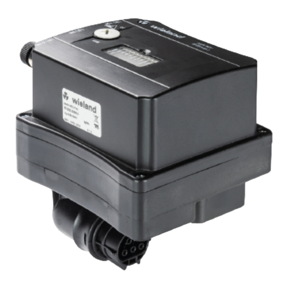
- Page 1 ® MCU FAC 3I/W 1.5 AS-i Motor starter Art.-No. 83.222.0009.5 Operating Manual Doc.-No. BA000628 Date: 04/2009 (Rev.A) © 2009 Wieland Electric GmbH...
- Page 3 Tel.: +49 (0)9 51 / 93 24-9 98 AT.TS@wieland-electric.com Saleshotline (for information about availability, lead times and prices): Tel.: +49 (0) 9 51 93 24-198 Fax: +33 1 30 32 07 17 info.adv@wieland-electric.com Wieland Electric GmbH | BA000628 (Rev.A) | 04/2009...
-
Page 4: Revision Listings
Naming alone does not imply that the trade mark is not protected by third party rights! Wieland Electric GmbH | BA000628 (Rev.A) | 04/2009... -
Page 5: Table Of Contents
Preparations ..............................18 Motor starter control ............................ 19 Test mode..............................26 Operation ......................28 Function terminal ............................28 Appendix ......................30 Dimensions ..............................30 Technical data .............................. 30 Ordering information ............................ 32 Wieland Electric GmbH | BA000628 (Rev.A) | 04/2009... -
Page 6: About This Operating Manual
"Caution" is also used to warn against unsafe practices or obvious misuse, "Caution" is also used for situations which may result in material damage without personal injury. Wieland Electric GmbH | BA000628 (Rev.A) | 04/2009... -
Page 7: Intended Use
All projection, program, installation, implementation, operation and Selecting podis maintenance work in connection with electronic products may only be personnel and executed by qualified personnel (e.g. skilled electrical workers, electrical qualifications engineers). Configuring and programming Wieland Electric GmbH | BA000628 (Rev.A) | 04/2009... -
Page 8: Configuration, Programming, Installation Activation And Operation
All electrical power must be removed from the automation devices prior to assembly or disassembly. Their design may not be changed. Wieland Electric GmbH | BA000628 (Rev.A) | 04/2009... -
Page 9: Service And Maintenance
1.7 Hazards due to Electrical Energy The user must ensure that unauthorized and improper intervention is stopped. Personnel must be familiar with all the warnings, notes and measures described in these operating instructions. Wieland Electric GmbH | BA000628 (Rev.A) | 04/2009... -
Page 10: Device Description
The motor starter can be addressed via the AS-i manual control unit (83.209.2204.0), which is connected with the programmer cable (83.209.2205.0) via the integrated address jack (Cinch). Motor currents can be set using the handheld terminal for test purposes Wieland Electric GmbH | BA000628 (Rev.A) | 04/2009... -
Page 11: Mechanical Assembly/ Housing
LED display (status, error) Addressing jack AS-i connection X7, X8 Input Sensors 3-phase input voltage (400 V) 3-phase motor output 2.3.2 3-phase connectors Input X1 Motor output X4 (male, black) (female, black) Wieland Electric GmbH | BA000628 (Rev.A) | 04/2009... - Page 12 Input Yellow IN1 Input Yellow IN0 Input AS-i Fault Fault AS-i 10 Green AS-i Power Voltage supply ok. NOTE Detailed descriptions and possible trouble shooting can be found in section 8.1,"Function control". Wieland Electric GmbH | BA000628 (Rev.A) | 04/2009...
-
Page 13: Technical Information
2.4 Technical information 2.4.1 Installation dimensions 2.4.2 Block diagram As-i + As-i - AS-i / μC LED's ADDR ADDR Addressing jack M12, A-coding Flat cable adapter X7, X8 M12, A-coding RST20i5 black not allocated Wieland Electric GmbH | BA000628 (Rev.A) | 04/2009... -
Page 14: Installation
Proceed as follows for installation on the substructure: Installation: Procedure 1. Screw the device to the base plate with two fastening screws M4 [a] (see drawing in "Conductor assignments"). Use washers. Wieland Electric GmbH | BA000628 (Rev.A) | 04/2009... - Page 15 (torque 1.2 Nm). 2. Screw in all (also unneeded) contact screws into the flat cable (Torque 1,0 Nm). podis Insert the MCU in the flat cable outlet and arrest the locking lever. Wieland Electric GmbH | BA000628 76| 04/2009...
-
Page 16: Electric Installation
Plug programming jack; b– AS-i connection; c– Digital outputs; d– Energy bus connector; e– Motor connection plug 3.2.1 Power line connection Proceed as follows for connecting the field distributor to the energy bus: Wieland Electric GmbH | BA000628 (Rev.A) | 04/2009... - Page 17 Connect AS-i interface X5 (see illustration 2-2) of the motor starter via the yellow AS-I cable to the AS-i network. Connection via the AS-i connection clip and the AS-i spur are recommended. Wieland Electric GmbH provides both parts as accessories (see appendix for ordering information). 3.2.4 Sensor connection...
-
Page 18: Activation And Parameterization
If operating mode "Read and write data" is selected with the address device, the motor can be controlled by setting output bits. Additional information about test mode can be found in section 5.4 "Test mode". Wieland Electric GmbH | BA000628 (Rev.A) | 04/2009... -
Page 19: Motor Starter Control
32-65535 0024 INT16 FFFF 65535 Configuration parameter bit coded, see table 0025 INT16 07D0 2000 Measuring constant (ms) 3000-FFFF 12288-65535 1-09F6 0026 INT16 0064 Deactivation constant 1-2550 (see table) 0027 INT16 0000 reserved Wieland Electric GmbH | BA000628 (Rev.A)| 04/2009... - Page 20 = 30d = 0x001E Pause on reverse = 500d = 0x01F4 Configuration parameters (left/right run, main relay in normal operation) = 0xFFFF = 2500dec = 0x09C4 Measuring constant Deactivation constant = 714dec = 0x02CA Wieland Electric GmbH | BA000628 (Rev.A) | 04/2009...
- Page 21 • Type of drive and motor performance • Application in e.g. materials handling technology • Environmental conditions, installation protection from incorrect turning direction etc. Wieland Electric GmbH | BA000628 (Rev.A)| 04/2009...
- Page 22 4.2.3.1 Minimal current (parameter 0x0021) This function enables motor deactivation during under load. This value can be selected in such a way that a motor with lower power can be operated without parameterized motor protection. Wieland Electric GmbH | BA000628 (Rev.A) | 04/2009...
- Page 23 Bit 2: "1"= reserved … Bit D: "1"= reserved Bit E: „1“ = enable move relay (move relay works in normal operation) Bit E: "0" = disable move relay (move relay is constantly deactivated) Wieland Electric GmbH | BA000628 (Rev.A)| 04/2009...
- Page 24 The tripping time of safety equipment is to have an effect in accordance to diagrams about the parameter "deactivation constant." Depending on the size of the value, the trip characteristic and motor protection responsiveness is optimized depending on motor size and load characteristics. Wieland Electric GmbH | BA000628 (Rev.A) | 04/2009...
- Page 25 4.2.6 Read ID string (Read_Identificationr_String) profile 7.4 The following values are transferred to the AS-i master when calling up this function: 03 2d 07 10 20 03 07 17 03 00 00 01 Wieland Electric GmbH | BA000628 (Rev.A)| 04/2009...
-
Page 26: Test Mode
2 Data write of the The value is transferred with the "PRG" key. The LEDs "M fwd" and "M rev" blink podis simultaneously on the MCU and thus display the changed settings. Wieland Electric GmbH | BA000628 (Rev.A) | 04/2009... - Page 27 • The AS Interface Handheld only transfers data as long as the "PRG" or "ADR" key is pressed. • By activating Watchdog, outputs are immediately reset if the "PRG" or "ADR" key is released and AS-i telegrams are received. Wieland Electric GmbH | BA000628 (Rev.A)| 04/2009...
-
Page 28: Operation
Motor switches off due to overload Check motor current set values, reduce motor load Switches off due to asymmetrical phase currents (motor failure), brake activation via L2/L3 Wieland Electric GmbH | BA000628 (Rev.A) | 04/2009... - Page 29 (leads to overload deactivation) Motor deactivation due to overload Check power line and motor or short circuit or start-up test connector without line phase L1 = off; = glows; =flashing; =blinks alternately Wieland Electric GmbH | BA000628 (Rev.A)| 04/2009...
-
Page 30: Appendix
5-pin (black) RST20i5 plug Contact blocks Electronic power switch Operating cycles Max. 120 W load-dependent Switching times typ. 10 ms Mode DB (EN 60149-1-1 und 1-3), S3 max. runtime 10 minutes Wieland Electric GmbH | BA000628 (Rev.A) | 04/2009... - Page 31 Automatic error reset via process image Approvals AS-i Immunity meets EN 61800-3 Emitted interference meets EN 61800-3 as well as limit value class A according to EN 55011 EN 55022 Climate class 3 K3 Type of cooling Self-cooling Wieland Electric GmbH | BA000628 (Rev.A)| 04/2009...
-
Page 32: Ordering Information
96.443.1084.1, however cable length: 6.0 m 96.443.6084.1 like 96.443.1084.1, however cable length: 7.0 m 96.443.7084.1 like 96.443.1084.1, however cable length: 8.0 m 96.443.8084.1 like 96.443.1084.1, however cable length: 9.0 m 96.443.9084.1 Wieland Electric GmbH | BA000628 (Rev.A) | 04/2009... - Page 33 6 | Appendix 6.1.1 AS-i accessories AS-i Adapter M12 83.209.2201.0 Converted AS-i connection cable 83.209.2203.0 0.3 m, 2xM12 (jack, plug) AS-i Handheld AS-i PPG 1 83.209.2204.0 Programming cable AS-i 1.5 m, 83.209.2205.0 suitable for ASi-PPG Wieland Electric GmbH | BA000628 (Rev.A)| 04/2009...
- Page 34 Appendix | 6 Wieland Electric GmbH Brennerstraße 10-14 D-96052 Bamberg Tel. +49 (0) 951 / 9324 -0 Fax +49 (0) 951 / 9324 -198 Email: info@wieland-electric.com www.wieland-electric.com...
Need help?
Do you have a question about the podis MCU FAC 3I/W 1.5 and is the answer not in the manual?
Questions and answers