Nortel 2000 Hardware Installation Manual
Application gateway
Hide thumbs
Also See for 2000:
- Using manual (405 pages) ,
- Software reference manual (359 pages) ,
- User manual (86 pages)
Table of Contents
Advertisement
Quick Links
Title page
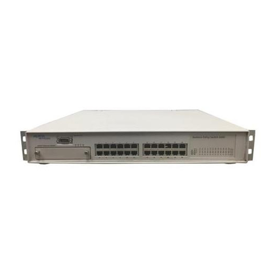
Nortel Application Gateway 2000
Nortel Application Gateway Release 6.1
Hardware Installation Guide
Installation
Document Number: NN42360-303
Document Release: Standard 01.06
Date: March 2007
Year Publish FCC TM
Copyright © 2006–2007 Nortel Networks. All rights reserved.
Produced in Canada
The information in this document is subject to change without notice. The statements, configurations, technical
data, and recommendations in this document are believed to be accurate and reliable, but are presented
without express or implied warranty. Users must take full responsibility for their applications of any products
specified in this document. The information in this document is proprietary to Nortel Networks.
Nortel, Nortel (Logo), the Globemark, SL-1, Meridian 1, and Succession are trademarks of Nortel Networks.
Advertisement
Table of Contents

Related Manuals for Nortel 2000


Summary of Contents for Nortel 2000
- Page 1 Users must take full responsibility for their applications of any products specified in this document. The information in this document is proprietary to Nortel Networks. Nortel, Nortel (Logo), the Globemark, SL-1, Meridian 1, and Succession are trademarks of Nortel Networks.
-
Page 3: Table Of Contents
Contents Preface Audience Organization Conventions Related Documentation Online Documentation Application Gateway Overview C H A P T E R Power Connectors Specifications, Safety, and Other Information Hardware Installation and Initial Configuration C H A P T E R Readiness Checklist Materials Required Rack Mounting Connecting and Powering up the Application Gateway... - Page 4 Contents Application Gateway Hardware Installation Guide...
-
Page 5: Preface
This preface describes who should read the Application Gateway Hardware Installation Guide, how it is organized, and its document conventions. Audience This installation guide is intended for service technicians who will install the Application Gateway 2000. Organization This guide is organized as follows: Chapter... -
Page 6: Conventions
Conventions Conventions This guide uses the following conventions: Convention boldface font boldface screen font Notes use the following conventions: Means reader take note. Notes contain helpful suggestions or other Note important information. Tips use the following conventions: Means the following information will help you solve a problem. The tips information might not be troubleshooting or even an action, but could be useful information. -
Page 7: Online Documentation
Online Documentation Online Documentation To access Nortel Networks documentation online, click the Technical Documentation link under Support on the Nortel Networks home page: http://www.nortelnetworks.com/ Application Gateway Hardware Installation Guide... - Page 8 Online Documentation viii Application Gateway Hardware Installation Guide...
-
Page 9: Chapter 1 Application Gateway Overview
Application Gateway Overview Note Nortel Application Gateway 2000 The applications delivered to Nortel IP Phones and other devices include Nortel Voice Office applications, Nortel Guest Services, and transformed business applications. The location of an Application Gateway in a network is largely based on the configuration of the existing network. -
Page 10: Power
Chapter 1 Application Gateway Overview Power Power The power cord connector is located on the left side on the back of the Application Gateway. When the power LED, on the front panel, is illuminated, the power is on.The power control button is on the front panel. -
Page 11: Chapter 1 Application Gateway Overview Connectors
Power-on LED: When this LED is lit, it indicates that the server is turned on. When this LED is off, it indicates that ac power is not present, or the power supply or the LED itself has failed. If this LED is off, it does not mean that there is no electrical power Note in the server. -
Page 12: Back Connectors
Chapter 1 Application Gateway Overview Connectors Back Connectors Figure 2 Figure 2 Power-cord connector: Connect the power cord to this connector. Serial connector: The DB-9 serial port is used to connect the Application Gateway to a computer that is capable of running terminal emulation software. -
Page 13: Rear Leds
Rear LEDs Figure 3 Figure 3 Ethernet transmit/receive activity LED: This LED is on each Ethernet connector. When this LED is lit, it indicates that there is activity between the server and the network. Ethernet speed LED: This LED is on each Ethernet connector. When this LED is lit, it indicates that the Ethernet network speed is 1 Gbps. - Page 14 Chapter 1 Application Gateway Overview Specifications, Safety, and Other Information Application Gateway Hardware Installation Guide...
-
Page 15: Chapter 2 Hardware Installation And Initial Configuration
Chapter 2 Chapter Hardware Installation and Initial Configuration The following topics describe how to connect the Nortel Application Gateway 2000 to the network and perform initial configuration: Readiness Checklist, page 7 • Materials Required, page 8 • Rack Mounting, page 9 •... -
Page 16: Materials Required
Chapter 2 Hardware Installation and Initial Configuration Materials Required Table 1 Have you: Obtained the following: screwdrivers • an ECOS 1023 POW-R-MATE or similar type of • multimeter appropriate cable terminating tools • a computer to be connected directly to the Application •... -
Page 17: Chapter 2 Hardware Installation And Initial Configuration Rack Mounting
Refer to the IBM Rack Installation Instructions provided with the server. Connecting and Powering up the Application Gateway In geographic regions that are susceptible to electrical storms, Nortel recommends that you plug the Application Gateway into an AC surge suppressor. -
Page 18: Chapter 2 Hardware Installation And Initial Configuration Connecting And Powering Up The Application Gateway
Chapter 2 Hardware Installation and Initial Configuration Connecting and Powering up the Application Gateway If the Application Gateway can access the connected device (router, • application server, etc.) from the same subnet as it receives client requests, use one network cable. Connect Application Gateway interface port 0 (ethernet 2) to your network. - Page 19 Set the COM port on the maintenance terminal as follows: Terminal type: VT100 • Speed: 19200 • Data bits: 8 • Parity: none • Stop bits: 1 • Flow control: hardware • The Application Gateway is shipped with the Admin/Serial port Note set to 19200 Bit/s.
- Page 20 Chapter 2 Hardware Installation and Initial Configuration Connecting and Powering up the Application Gateway To configure the Application Gateway using a serial console: In the Application Gateway serial console, enter the default login root and the default password rootadmin. Type 0 and press Enter to choose Express Setup. Enter the IP address and netmask for Interface 0 when prompted.
-
Page 21: Alternate Procedure If Using A Crossover Cable
Alternate Procedure if Using a Crossover Cable If you prefer to use the Web-based Administration Tool rather than a serial console to change the network settings of the Application Gateway, follow the procedure described in this topic. You can use this procedure to perform the initial installation or to change the network settings after installation is completed. - Page 22 Chapter 2 Hardware Installation and Initial Configuration Connecting and Powering up the Application Gateway Enter the Subnet Mask Enter the Default Gateway and click OK twice. Change the Application Gateway network settings: From a web browser on the connected PC, enter https://10.20.30.40:9001 to access the Application Gateway Administration Tool.
-
Page 23: Installing Licenses
Figure 6 Remove the CD-ROM and restart the Application Gateway. Install licenses as described in Refer to the Application Gateway Administration Guide for additional operating information. You can download all documentation from the Application Gateway Administration Tool. Installing Licenses To upload license files to the Application Gateway: In the Administration Tool, go to the Administration >... -
Page 24: Third-Party Software
Chapter 2 Hardware Installation and Initial Configuration Connecting and Powering up the Application Gateway Third-Party Software We recommend that you not install any third-party software on the Application Gateway. Problems caused by the installation of third-party software are not supported. Application Gateway Hardware Installation Guide... - Page 26 Users must take full responsibility for their applications of any products specified in this document. The information in this document is proprietary to Nortel Networks. Nortel, Nortel (Logo), the Globemark, SL-1, Meridian 1, and Succession are trademarks of Nortel Networks. Publication number: NN42360-303 Document release: Standard 01.06...
Need help?
Do you have a question about the 2000 and is the answer not in the manual?
Questions and answers