Table of Contents
Advertisement
Quick Links
Advertisement
Table of Contents

Subscribe to Our Youtube Channel
Related Manuals for Copper Mountain Technologies R60


Summary of Contents for Copper Mountain Technologies R60
- Page 1 631 E New York Street | Indianapolis, IN 46202 USA www.coppermountaintech.com Network Analyzers using RVNA and RNVNA software Operating and Programming manual Revision 22.3.1 27.10.2022 U.S.: +1.317.222.5400 Singapore: +65.63.23.6546 Latin America: +1.9154.706.5920 EMEA: +44 75 03 69 21 13...
-
Page 2: Table Of Contents
Principles of Operation ....................42 Principle of Measuring S-parameters ............... 44 Summarized Description of Hierarchy ..............46 Internal Data Processing .................... 49 Instrument Series ..............................52 R60 ..........................53 R140 ..........................55 R140B ........................... 57 R180 ..........................60 RNVNA ......................... 63 R54 .......................... - Page 3 Contents SWR and Reflection Coefficient Phase Analysis Using Markers ......90 User Interface ................................. 93 Left and Right Softkey Menu Bars ................94 Top Menu Bar ......................96 Channel Window Layout and Functions ..............100 Channel Title Bar ....................102 Trace Status Field ....................
- Page 4 Contents Reverse Sweep Mode ..................158 Trigger Settings ......................159 Trigger State Diagram ..................160 Trigger Source ...................... 165 Trigger Mode ......................167 External Trigger Settings ..................169 External Trigger Event ..................170 External Trigger Polarity .................. 173 External Trigger Position ................175 External Trigger Delay ..................
- Page 5 Contents Phase Offset Setting .................... 231 Measurement Optimization ..................232 IF Bandwidth Setting .................... 236 Averaging Setting ....................238 Smoothing Setting ....................241 Quick Settings Using a Mouse ................243 Active Channel Selection ..................244 Active Trace Selection ..................245 Measured Parameter Setting ................
- Page 6 Contents Analyzer Test Port Definition ................277 Calibration Steps ....................278 Calibration Standards and Calibration Kits ............279 Types of Calibration Standards ................280 Calibration Standards Definition ................ 281 Calibration Standard Model ................282 Data-Based Calibration Standards ............... 286 Gender of Calibration Standard ................287 Calibration Kit Management ................
- Page 7 Contents Automatic Calibration Module Features ............355 Automatic Calibration Procedure ............... 357 Optimization of N-port calibration procedure ............ 366 Confidence Check Procedure ................367 Erasing the User Characterization ..............372 Error Correction Status ..................... 374 Error Correction Disabling ..................376 System Impedance Z0 ....................
- Page 8 Contents Memory Trace Function .................... 439 Mathematical Operations ..................445 Trace Hold ........................447 Fixture Simulation ...................... 450 Port Extension ....................... 451 Automatic Port Extension ..................455 Port Reference Impedance (Z) Conversion ............458 De-embedding ...................... 462 Embedding ......................465 Time Domain Transformation ..................
- Page 9 Contents Analyzer Presetting ....................559 Graph Printing ......................560 System Correction Setting ..................564 Analyzer Model Selection ..................566 Reference Source Setting ..................570 Reference Output Setting ..................573 Managing Licenses ....................574 User Interface Setting ....................583 Demo Mode ....................... 589 Standby Mode ......................
- Page 10 Contents Optional Subsystems ................... 619 Long and Short Formats ..................620 Case Sensitivity ....................621 Parameters ......................622 Numeric Values ....................623 Multiplier Prefixes .................... 624 Notations ......................625 Booleans ......................626 Character Data ....................627 String Parameters ................... 628 Numeric Lists ....................
- Page 11 Contents Error Handling ....................... 650 COM Automation Data Types ................652 Measurement Data Arrays .................. 653 Internal Data Arrays ....................654 Command Reference ....................660 SCPI Command Tree ..................662 IEEE488.2 Common Commands ............... 663 *CLS ........................664 *ESE ......................... 666 *ESR? .......................
- Page 12 Contents CALC:DATA:XAX? ..................707 CALC:FILT:TIME ..................... 709 CALC:FILT:TIME:CENT .................. 711 CALC:FILT:TIME:STAR .................. 713 CALC:FILT:TIME:SHAP ................. 715 CALC:FILT:TIME:SPAN ................. 717 CALC:FILT:TIME:STAT .................. 719 CALC:FILT:TIME:STOP .................. 721 CALC:FORM ....................723 CALC:FSIM:SEND:DEEM:PORT:STAT ............726 CALC:FSIM:SEND:DEEM:PORT:USER:FIL ..........728 CALC:FSIM:SEND:PMC:PORT:STAT ............730 CALC:FSIM:SEND:PMC:PORT:USER:FIL ..........732 CALC:FSIM:SEND:ZCON:PORT:Z0 ............
- Page 13 Contents CALC:LIM:DATA ..................... 764 CALC:LIM:DISP ....................766 CALC:LIM:FAIL? ..................... 768 CALC:LIM:OFFS:AMPL ................. 770 CALC:LIM:OFFS:STIM ................... 772 CALC:LIM:REP:ALL? ..................774 CALC:LIM:REP:POIN? ................... 776 CALC:LIM:REP? ..................... 778 CALC:MARK ....................780 CALC:MATH:DEL ................... 782 CALC:MATH:FUNC ..................783 CALC:MATH:MEM ..................785 CALC:MARK:ACT ................... 786 CALC:MARK:BWID ..................
- Page 14 Contents CALC:MARK:FUNC:TTR ................819 CALC:MARK:FUNC:TYPE ................821 CALC:MARK:REF ................... 823 CALC:MARK:SET ................... 825 CALC:MARK:X ....................827 CALC:MARK:Y? ....................829 CALC:MST ....................... 831 CALC:MST:DATA? ..................833 CALC:MST:DOM ..................... 835 CALC:MST:DOM:STAR ................. 837 CALC:MST:DOM:STOP ................. 839 CALC:PAR:COUN ..................841 CALC:PAR:DEF ....................843 CALC:PAR:SEL ....................
- Page 15 Contents CALC:TRAN:TIME:KBES ................875 CALC:TRAN:TIME:LPFR ................877 CALC:TRAN:TIME:REFL:TYPE ..............878 CALC:TRAN:TIME:SPAN ................880 CALC:TRAN:TIME:STAR ................882 CALC:TRAN:TIME:STOP ................884 CALC:TRAN:TIME:STAT ................886 CALC:TRAN:TIME:STEP:RTIM ..............888 CALC:TRAN:TIME:STIM ................. 890 CALC:TRAN:TIME:UNIT ................. 892 DEVices ........................ 894 DEV:ADDN ...................... 895 DEV:COUN? ....................896 DEV:MOVD ......................
- Page 16 Contents DISP:ENAB ...................... 919 DISP:FSIG ......................921 DISP:IMAG ....................... 923 DISP:MAX ......................925 DISP:SPL ......................927 DISP:UPD ......................929 DISP:WIND:ACT ....................930 DISP:WIND:ANN:MARK:ALIG ............... 932 DISP:WIND:ANN:MARK:SING ............... 934 DISP:WIND:MAX ..................... 936 DISP:WIND:SPL ....................938 DISP:WIND:TITL ....................940 DISP:WIND:TITL:DATA .................. 942 DISP:WIND:TRAC:ANN:MARK:POS:X ............
- Page 17 Contents HCOP ........................ 970 HCOP:DATE:STAM ..................971 HCOP:IMAG ..................... 973 HCOP:PAIN ...................... 975 HCOP:RECT ....................977 INITiate ........................978 INIT ........................979 INIT:CONT ......................981 MMEMory ......................983 MMEM:COPY ....................986 MMEM:DEL ...................... 987 MMEM:LOAD ....................988 MMEM:LOAD:CBL ..................989 MMEM:LOAD:CHAN ..................
- Page 18 Contents MMEM:STOR:FDAT ..................1011 MMEM:STOR:IMAG ..................1012 MMEM:STOR:LIM ..................1013 MMEM:STOR:RLIM ..................1014 MMEM:STOR:SEGM ..................1015 MMEM:STOR:SNP ..................1016 MMEM:STOR:SNP:FORM ................1018 MMEM:STOR:SNP:TYPE:S1P ..............1020 MMEM:STOR:SNP:TYPE:S2P ..............1022 MMEM:STOR:STYP ..................1024 MMEM:TRAN? ....................1026 OUTP ........................1027 SENSe ........................ 1029 SENS:AVER ....................
- Page 19 Contents SENS:CORR:COLL:CKIT:LAB ..............1065 SENS:CORR:COLL:CKIT:RES ..............1067 SENS:CORR:COLL:CKIT:STAN:C0 ............1068 SENS:CORR:COLL:CKIT:STAN:C1 ............1070 SENS:CORR:COLL:CKIT:STAN:C2 ............1072 SENS:CORR:COLL:CKIT:STAN:C3 ............1074 SENS:CORR:COLL:CKIT:STAN:DEL ............1076 SENS:CORR:COLL:CKIT:STAN:FMAX ............ 1078 SENS:CORR:COLL:CKIT:STAN:FMIN ............1080 SENS:CORR:COLL:CKIT:STAN:HWR ............1082 SENS:CORR:COLL:CKIT:STAN:L0 ............1084 SENS:CORR:COLL:CKIT:STAN:L1 ............1086 SENS:CORR:COLL:CKIT:STAN:L2 ............1088 SENS:CORR:COLL:CKIT:STAN:L3 ............
- Page 20 Contents SENS:CORR:COLL:ECAL:SOLT1 ............. 1118 SENS:CORR:COLL:ECAL:SOLT2 ............. 1119 SENS:CORR:COLL:ECAL:UCH ..............1121 SENS:CORR:COLL:LOAD ................1123 SENS:CORR:COLL:OPEN ................1125 SENS:CORR:COLL:SAVE ................1127 SENS:CORR:COLL:SHOR ................1129 SENS:CORR:COLL:THRU ................1131 SENS:CORR:COLL:METH:ERES .............. 1133 SENS:CORR:COLL:METH:OPEN .............. 1135 SENS:CORR:COLL:METH:SHOR .............. 1137 SENS:CORR:COLL:METH:SOLT1 ............1139 SENS:CORR:COLL:METH:SOLT2 ............1141 SENS:CORR:COLL:METH:THRU ..............
- Page 21 Contents SENS:CORR:EXT:PORT:TIME ..............1171 SENS:CORR:IMP ..................1173 SENS:CORR:STAT ..................1175 SENS:CORR:TRAN:TIME:FREQ ..............1177 SENS:CORR:TRAN:TIME:LOSS ..............1179 SENS:CORR:TRAN:TIME:RVEL ..............1181 SENS:CORR:TRAN:TIME:STAT ..............1183 SENS:CORR:TYPE? ..................1185 SENS:FREQ:DATA? ..................1187 SENS:FREQ:CENT ..................1189 SENS:FREQ:SPAN ..................1191 SENS:FREQ:STAR ..................1193 SENS:FREQ:STOP ..................1195 SENS:ROSC:SOUR ..................
- Page 22 Contents SOUR:POW ....................1218 SOUR:POW:STAT ..................1220 STATus ........................ 1222 STAT:OPER? ....................1226 STAT:OPER:COND? ..................1227 STAT:OPER:ENAB ..................1228 STAT:OPER:NTR ..................1230 STAT:OPER:PTR ..................1232 STAT:PRES ....................1234 STAT:QUES:COND? ..................1235 STAT:QUES:ENAB ..................1236 STAT:QUES:LIM:CHAN:COND? ..............1238 STAT:QUES:LIM:CHAN:ENAB ..............1239 STAT:QUES:LIM:CHAN:NTR ..............
- Page 23 Contents STAT:QUES:RLIM:COND? ................1266 STAT:QUES:RLIM:ENAB ................1267 STAT:QUES:RLIM:NTR ................1269 STAT:QUES:RLIM:PTR ................1271 STAT:QUES:RLIM? ..................1273 STAT:QUES? ....................1274 SYSTem ......................1275 SYST:COMM:ECAL:IMP ................1277 SYST:COMM:ECAL:TEMP:SENS? ............1279 SYST:COMM:ECAL:THRU ................1280 SYST:CONN:SER ..................1281 SYST:CORR ....................1282 SYST:DATE ....................1284 SYST:ERR? ....................
- Page 24 Contents TRIG:EXT:SLOP .................... 1306 TRIG:EXT:POS ....................1308 TRIG:OUTP:FUNC ..................1310 TRIG:OUTP:POL ................... 1312 TRIG:OUTP:STAT ..................1314 TRIG:POIN ...................... 1316 TRIG:SING ...................... 1318 TRIG:SOUR ....................1320 TRIG:STAT? ....................1322 TRIG:WAIT ...................... 1323 Programming Tips ....................1325 Program Sweep Initiation and Waiting ............1326 Using External Trigger ..................
- Page 25 Contents General Overview ....................1366 Modification ....................1367 ACM2506 ....................... 1369 ACM2509 ....................... 1372 ACM2520 ....................... 1375 ACM2543 ....................... 1378 ACM4509 ....................... 1381 ACM4520 ....................... 1384 ACM2708 ....................... 1388 ACM4000T ..................... 1390 ACM6000T ..................... 1392 ACM8000T ..................... 1395 ACM8400T ..................... 1398 Protective Housing ..................
- Page 26 Contents One-Path Two-Port and Full Two-Port Calibration ........1423 Module Work Session ................... 1424 Module Preparation for Calibration ............. 1424 Parameters Setting ..................1425 Calibration ......................1426 Measurement Errors ..................1427 Calibration Types ..................1428 Full One-Port Calibration ................1428 One-Path Two-Port Calibration ..............
- Page 27 Contents Handling and storage ..................1450 Gauging ....................... 1451 Cleaning ......................1455 Connecting and Disconnecting ................. 1458 Glossary ................................... 1462 Copyright ................................1464 Page 27...
-
Page 28: Introduction
Introduction This manual contains design, specifications, functional overview, and detailed operation procedures for the Copper Mountain Technologies Vector Network Analyzer, to ensure effective and safe use of its technical capabilities. Maintenance and operation of the Analyzer should be performed by qualified engineers with basic experience in the operation of microwave circuits. -
Page 29: Scope Of Manual
Scope of Manual This manual covers for the 1-port Vector Network Analyzer (VNA) controlled by the RVNA software version 22.4.0 and N-port mode of VNA (RNVNA) controlled by the RNVNA software version 22.4.0. The Analyzer models are listed below: · ·... -
Page 30: Safety Instructions
Analyzer as a CAT II, III, or IV device. The Analyzer has been tested as a stand-alone device and in combination with the accessories supplied by Copper Mountain Technologies, in accordance with the requirements of the standards described in the Declaration of Conformity. If the Analyzer is integrated with another system, compliance with related regulations and safety requirements are to be confirmed by the builder of the system. - Page 31 adhered to, could result in damage to or destruction of part or all of the instrument. This sign denotes important information. It calls attention to a NOTE procedure, practice, or condition that is essential for the user to understand. Resistance R1 is a must for wrist straps. The R1 rating is selected from a range of 1 MΩ.
-
Page 32: General Overview
General Overview The Vector Network Analyzer is designed for use in the process of development, adjustment, and testing of various electronic devices in industrial and laboratory facilities, including operation as a component of an automated measurement system. The Analyzer is designed for operation with an external PC, which is not supplied with the Analyzer. -
Page 33: Measurement Capabilities
Measurement Capabilities Measurement Capabilities Measured parameters S11, Cable loss, when using a 1-port VNA. S-parameters when using two or more Analyzers (separately or as a part of an RNVNA): · Sii, where i is a value from 1 to N is taken. ·... - Page 34 Sweep setup features Sweep type Linear frequency sweep, logarithmic frequency sweep, and segment frequency sweep. Measured points per From 2 to 100,001 for 1-port VNA. sweep From 2 to 16,001 for RNVNA. Segment sweep frequency sweep within several user-defined segments. Frequency range, number of sweep points, IF bandwidth and measurement delay should be set for each segment.
- Page 35 Trace display functions Trace type Data trace, memory trace, or simultaneous data and memory traces. Trace math Data trace modification by math operations: addition, subtraction, multiplication or division of measured complex values and memory data. Autoscaling Automatic selection of scale division and reference level value to have the trace most effectively displayed.
- Page 36 Accuracy enhancement Calibration Calibration of a test setup (which includes the Analyzer and adapter) significantly increases the accuracy of measurements. Calibration allows to correct the errors caused by imperfections in the measurement system: system directivity, source match, and tracking. Calibration methods The following calibration methods are available: ·...
- Page 37 The user can select one of the predefined calibration calibration kits kits of various manufacturers or define own calibration kits. Electronic calibration Copper Mountain Technologies’ automatic calibration modules modules (ACM’s) make Analyzer calibration faster and easier than traditional mechanical calibration and provides the highest accuracy.
- Page 38 Marker functions Data markers Up to 16 markers for each trace. A marker indicates stimulus value and the measured value in a given point of the trace. Reference marker Enables indication of any maker values as relative to the reference marker. Marker search Search for max, min, peak, or target values on a trace.
- Page 39 Data analysis Port impedance The function of conversion of the S-parameters conversion measured at 50 port into the values, which could be determined if measured at a test port with arbitrary impedance. NOTE: The function is applicable for reflection coefficients (S11, S22 etc.) measurement only. De-embedding The function allows to exclude mathematically the effect of the fixture circuit connected between the calibration...
- Page 40 Time domain function performs data transformation from transformation frequency domain into response of the DUT to radiopulse in time domain. Time domain span is set by the user arbitrarily from zero to maximum, which is determined by the frequency step. Windows of various forms allow better tradeoff between resolution and level of spurious sidelobes.
- Page 41 Other features Analyzer control Using external personal computer via USB interface. Familiar graphical Graphical user interface based on Windows operating user interface system ensures fast and easy Analyzer operation. The software interface of Analyzers is compatible with modern tablet PCs and laptops. Saving trace data Saving the traces in graphical format and saving the data in Touchstone and *.CSV (comma separated...
-
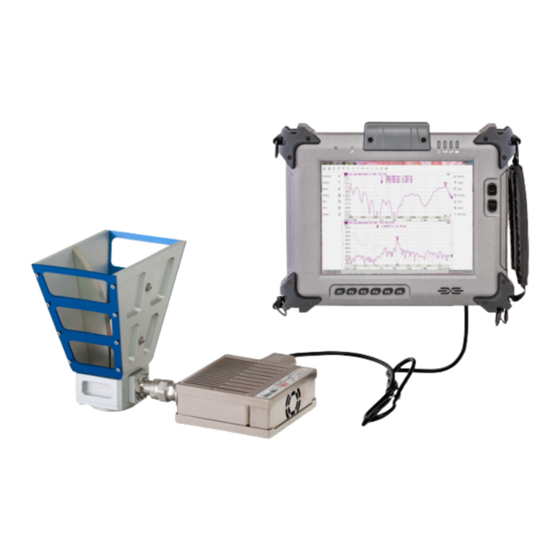
Page 42: Principles Of Operation
Principles of Operation The Analyzer consists of the Analyzer Unit, some supplementary accessories, and a personal computer (which is not supplied with the package). The Analyzer Unit is powered and controlled by PC via USB-interface. The block diagram of the Analyzer is presented in figure below. - Page 43 Optionally, TD-16 trigger signal distributors and FD-16 reference frequency distributors can be used. Using the TD-16 trigger signal distributor make it possible to connect all the analyzers with the common trigger signal bus that allows increase in measurement speed. Using the FD-16 reference frequency signal distributor makes it possible to connect all the analyzers with the common reference frequency signal, allowing increase in measurement accuracy and speed.
-
Page 44: Principle Of Measuring S-Parameters
Principle of Measuring S-parameters The Analyzer emits a test signal (stimulus) out of a port connected to the DUT. The frequency of the test signal changes in the specified range discretely from point to point. At each frequency point, the Analyzer simultaneously measures the magnitude and phase of the signal transmitted through and reflected from the DUT. - Page 45 For example: For the measurement of S11, |S21|, ... , |S15.1|, |S16.1| parameters, test Port 1 will operate as a signal source. The incident and reflected waves will be measured by Port 1. The transmitted wave will be measured by Port 2, Port 3, ... Port16. For the measurement of |S12|, S22, ...
-
Page 46: Summarized Description Of Hierarchy
Summarized Description of Hierarchy The following hierarchy of measurement, processing, and display tools is used during operation of the Analyzer (See figure below): · Analyzer Hardware makes radio frequency measurements of the DUT parameters and performs primary processing of measurement results. ·... - Page 47 · Channel Windows – the diagram area in which the Channel is displayed. For a detailed description of the controls, see Channel Window Layout and Functions. · Software and Analyzer Controls: menu bar, analyzer status bar, and software button bar. For a detailed description of the controls, see Screen Layout and Functions.
- Page 48 · Time Domain Gating · S-Parameter Conversion · Limit Test Each channel window can display up to 4 charts for RVNA and up 16 charts for RNVNA simultaneously. Convenient placement of traces in the channel window is designated as Diagram. Traces can be placed in a single chart or grouped according to user settings in different charts.
-
Page 49: Internal Data Processing
Internal Data Processing The following figure shows a flowchart of the Analyzer's internal data processing flow. For a detailed description of remote control access to internal data arrays see in Internal Data Arrays. Data Processing Flowchart The Analyzer's internal data processing consists of the following stages: ·... - Page 50 · Acquire Cal Data is measuring calibration standards. Complex measured data of all standards are stored in memory. For more details see Calibration Methods Procedures. · Calc Error Terms is calculation of calibration coefficients based on measurement data of calibration standards in accordance with the selected calibration method.
- Page 51 · Time Domain is conversion of the measured S-parameter in the frequency domain into the response of the circuit under investigation in the time domain. Time Domain Transformation. · Gating is a removal of unwanted responses in the time domain. See Time Domain Gating.
-
Page 52: Instrument Series
Instrument Series This section describes the different models of Analyzers. Models of 1-port VNA: · · R140 · R140B · R180 · Models N-port mode of VNA: · RNVNA The top panel of each Analyzer are shown further in this section, along with the controls located on those panel. -
Page 53: R60
The top panel view of the Analyzers is represented in the figures below. R60 top panel R60 side panel Part of the R60 Test port The test port (type-N male 50 Ω) is intended for DUT connection. It is also used as a source of the stimulus signal and as a receiver of the response signal from the DUT. - Page 54 · Green blinking light is standby mode. In this mode the current consumption of the device from the USB port is minimum. · Green glowing light is normal device operation. USB Connector The mini USB 2.0 port is intended for connection to USB port of the personal computer via the supplied USB cable.
-
Page 55: R140
R140 The top panel view of the Analyzers is represented in the figures below. R140 top panel R140 side panel Part of the R140 Test port The test port (type-N male 50 Ω) is intended for DUT connection. It is also used as a source of the stimulus signal and as a receiver of the response signal from the DUT. - Page 56 LED Indicator The top panel is equipped with the READY/STANDBY LED indicator running in the following modes: · Green blinking light is standby mode. In this mode the current consumption of the device from the USB port is minimum. · Green glowing light is normal device operation.
-
Page 57: R140B
R140B The top panel view of the Analyzers is represented in the figures below. R140B top panel R140B rear panel Page 57... - Page 58 R140B side panel Part of the R140B Test port The test port is intended for DUT connection. The test port is type-N 50 Ω or 3.5 mm (See Hardware configurations). It is also used as a source of the stimulus signal and as a receiver of the response signal from the DUT.
- Page 59 External Trigger Signal Input/Output Connector External Trigger Signal Input allows the user to connect an external trigger source. Connector type is SMA female. 3.3v CMOS TTL compatible inputs magnitude have at least 1 µs pulse width. Input impedance is at least 10 kOhm. The External Trigger Signal Output port can be used to provide trigger to an external device.
-
Page 60: R180
R180 The top panel view of the Analyzers is represented in the figures below. R180 top panel Page 60... - Page 61 R180 side panel Part of the R180 Test port The test port is intended for DUT connection. The test port is type-N male 50 Ω or 3.5 mm (See Hardware configurations). It is also used as a source of the stimulus signal and as a receiver of the response signal from the DUT.
- Page 62 Power Cable Receptacle The power supply receptacle is intended for an external DC power supply voltage from 4.75 to 5.25 V; alternatively, the power supply can be powered by a battery, including a vehicle battery, through an appropriate vehicle power cable. The DC connection requires a 3.5x1.35 mm plug with positive center conductor.
-
Page 63: Rnvna
RNVNA RNVNA software allows using up to sixteen Analyzers simultaneously. This expands the list of parameters to be measured. It allows to additionally measure Scalar transfer coefficient in two directions, for example |S21| and |S12| of the DUT. The signal source can be only one device (active). The rest of devices (passive) work as a signal receiver. - Page 64 RNVNA top view Page 64...
- Page 65 Part of the RNVNA Test port The test port (type-N male 50 Ω) is intended for DUT connection. It is also used as a source of the stimulus signal and as a receiver of the response signal from the DUT. Ground Terminal Use the terminal for grounding.
-
Page 66: R54
The top panel view of the Analyzers is represented in the figures below. R60 top panel R60 side panel Part of the R54 Test port The test port (type-N male 50 Ω) is intended for DUT connection. It is also used as a source of the stimulus signal and as a receiver of the response signal from the DUT. - Page 67 USB Connector The mini USB 2.0 port is intended for connection to USB port of the personal computer via the supplied USB cable. Page 67...
-
Page 68: Preparation For Use
Connect the Analyzer to the PC using the USB Cable supplied in the package. Install the software that will be used to operate the Analyzer (The software can be found on the shipped flash-drive or on the Copper Mountain Technologies website). The software installation procedure is described in Software Installation. - Page 69 USB TYPE C TO USB 2.0 A MALE, 3A Page 69...
-
Page 70: Software Installation
Software Installation The software is installed to the external PC running under Windows operating system. The Analyzer is connected to the external PC via USB interface. Minimal system requirements for the PC WINDOWS 7 and Higher 1.5 GHz Processor 2 GB RAM USB 2.0 High Speed The supplied USB flash drive contains the following software: Flash drive contents... - Page 71 Software installation procedure is performed in two steps. The first one is the driver installation. The second step comprises installation of the software, documentation and other related files. Driver installation Connect the Analyzer to PC via the supplied USB cable. Windows will automatically...
-
Page 72: Rnvna Licensing
RNVNA software (See Managing Licenses). Free license is integrated into RNVNA software and allows to operate with up to 3 Analyzers. NOTE Contact your local Copper Mountain Technologies representative in case: · License file is lost or damaged. · 1-port VNA replacement. -
Page 73: Getting Started
Getting Started This section represents a sample session of the Analyzer. It describes the main techniques of measurement of reflection coefficient parameters of the DUT. SWR and reflection coefficient phase of the DUT will be analyzed. The instrument sends the stimulus to the input of the DUT and then receives the reflected wave. -
Page 74: Analyzer Preparation For Reflection Measurement
Analyzer Preparation for Reflection Measurement Turn on the Analyzer and warm it up for the period of time stated in the datasheet. READY STATE The bottom line of the screen displays the instrument status bar. It should read Ready. FEATURES Connect the DUT to the test port of the Analyzer. -
Page 75: Analyzer Presetting
Analyzer Presetting It is recommended resetting the Analyzer into the initial state before starting measurement session. The initial condition setting is described in Annex. NOTE Software can be controlled using mouse or a touchscreen. To restore the initial state of the Analyzer, use the softkey System in the right menu bar. -
Page 76: Stimulus Setting
Stimulus Setting After restoring the preset state of the Analyzer, the stimulus parameters will be as follows: · Full frequency range of the instrument. · Sweep type is linear. · Number of sweep points is 201. · Power level is high. ·... - Page 77 Page 77...
- Page 78 To set the stop frequency of the frequency range to 1 GHz select the Stop field and enter 1000 using the on-screen keypad. Complete the setting clicking Ok. Close the Stimulus dialog by clicking Ok. Page 78...
-
Page 79: If Bandwidth Setting
IF Bandwidth Setting For the current example, set the IF bandwidth to 3 kHz. To set the IF bandwidth use the softkey Average in the left menu bar. Then select the IFBW field in the Average dialog. To set the IF bandwidth in the IFBW dialog use the following softkeys 3 kHz. - Page 80 NOTE Also, selecting IF bandwidth could be done by double clicking on the required value in the IFBW. Page 80...
-
Page 81: Number Of Traces, Measured Parameter And Display Format Setting
Number of Traces, Measured Parameter and Display Format Setting In the current example, two traces are used for simultaneous display of the two parameters (SWR and reflection coefficient phase). To add the second trace, use the softkey Trace in the right menu bar. Then click the softkey Add Trace in the Trace dialog. - Page 82 To scroll up and down the formats list clicks on the list field and drag the mouse up or down accordingly. To select the first trace display format, click on Active Trace field, then on Format field. In the Format dialog click on SWR field. Complete the setting by clicking softkey Ok.
- Page 83 Page 83...
- Page 84 Close the dialogs by clicking softkey Ok. Page 84...
-
Page 85: Trace Scale Setting
Trace Scale Setting For a convenience in operation, change the trace scale using automatic scaling function. To set the scale of the active trace by the autoscaling function use the softkeys Scale in the right menu bar. Then click the softkey Auto Scale. Complete the setting by clicking softkey Ok. -
Page 86: Analyzer Calibration For Reflection Coefficient Measurement
Analyzer Calibration for Reflection Coefficient Measurement Calibration of the entire measurement setup — which includes the Analyzer, cables, and adapters involved for the DUT connection — greatly enhances the accuracy of the measurement. To perform full one-port calibration, prepare the kit of calibration standards: OPEN, SHORT, and LOAD. - Page 87 To select the calibration kit, use the softkey Calibration in the left menu bar. Then click the field Calibration Kit in the Calibration dialog. Then select the required kit from the Calibration Kits list and complete the setting by clicking softkey Ok. Page 87...
- Page 88 To perform full 1-port calibration, execute measurements of the three standards. After that the table of calibration coefficients will be calculated and saved into the memory of the Analyzer. Before start calibration, disconnect the DUT from the Analyzer. To perform full 1-port calibration use the softkey Calibration in the left menu bar. Connect an OPEN standard and click Open softkey in the Calibration dialog.
- Page 89 After clicking any of the Open softkeys, wait until the calibration procedure is completed. Connect a SHORT standard and click Short softkey. Connect a LOAD standard and click Load softkey. Wait until the calibration procedure is completed. To complete the calibration and calculate the table of calibration coefficients click Apply softkey in the Calibration dialog.
-
Page 90: Swr And Reflection Coefficient Phase Analysis Using Markers
SWR and Reflection Coefficient Phase Analysis Using Markers This section describes how to determine the measurement values at three frequency points using markers. In the current example, a reflection standard of SWR = 1.2 is used as a DUT. The Analyzer screen view is shown in figure below. SWR and reflection coefficient phase measurement example Page 90... - Page 91 To enable a new marker, use the softkey Marker in the left menu bar. Then click the softkey Add Marker in the Marker List dialog. Double click on the marker in the Marker List to activate the on-screen keypad and enter the marker frequency value. Page 91...
- Page 92 Complete the setting by clicking softkey Ok. Page 92...
-
Page 93: User Interface
User Interface The software on the PC screen is displayed as the Analyzer Screen. The Analyzer screen contains: · Channel windows to display measurement results in the form of traces and numerical values. · Top menu bar, left and right menu bars to control the Analyzer. -
Page 94: Left And Right Softkey Menu Bars
Left and Right Softkey Menu Bars The softkey menu bars in the left and right parts of the screen are the main menu of the software. Each softkey represents one of the submenus. The menu system is multilevel and allows to access to all the functions of the Analyzer. The menu softkeys can be controlled by a mouse or using a touch screen. - Page 95 Example of expanded or collapsed right menu bar Right softkey menu bar of RNVNA software contains addition softkey Devices (see figure below). Right softkey menu bar of RNVNA software Page 95...
-
Page 96: Top Menu Bar
Top Menu Bar The menu bar contains the functions of the most frequently used softkeys (See figure below). Top menu bar Description of the softkeys is given in the table below Softkey Description The softkey Recall State allows to recall the state from a file of the Analyzer state (See Analyzer... - Page 97 Softkey Description softkey Reference Marker allows to add the reference marker trace. To delete the reference marker reclick this key (See Reference Marker). The softkeys Add Trace and Delete Trace add and delete traces respectively (See Number of Traces). The softkey Memory trace enables trace saving into memory (See Memory Trace...
- Page 98 Softkey Description softkey Auto Scale allows to define the trace scale automatically so that the trace of the measured value could fit into the graph entirely (See Automatic Scaling). The softkey Auto Ref Value executes automatic selection of the reference level (See Reference Level Automatic...
- Page 99 If necessary, Top Menu Bar can be hidden. To show/hide the top menu bar use the softkey Display > Top panel. Page 99...
-
Page 100: Channel Window Layout And Functions
Channel Window Layout and Functions The channel windows display the measurement results in the form of traces and numerical values. The screen can display simultaneously up to 4 channel windows for RVNA and up to 16 channel windows for RNVNA. The analyzer hardware processes channels sequentially. - Page 101 Each channel window contains a Channel title (hidden by default) to be defined by the user, Trace status field to display the name and parameters of the traces, Diagram for displaying traces, as well as information about the channel status in the form of the Channel Status Bar.
-
Page 102: Channel Title Bar
Channel Title Bar The channel title feature allows for a comment to be entered for each channel window. The channel title bar can be hidden to gain more screen space for the trace diagram. Channel title bar Page 102... - Page 103 To show/hide the channel title bar use the softkey Display. Click on Caption field in the opened dialog. To edit the channel title, click on the softkey Edit to recall the on-screen keypad. SCPI DISPlay:WINDow:TITLe, DISPlay:WINDow:TITLe:DATA Page 103...
-
Page 104: Trace Status Field
Trace Status Field The trace status field displays the name and parameters of a trace. The number of lines in the field depends on the number of traces in the channel. The trace status field is represented in the figure below. Trace status field Each line contains the data on one trace of the channel: ·... - Page 105 Status Symbols Definition OPEN response calibration SHORT response calibration Full 1-port calibration Transmission normalization (RNVNA only) Error Correction F1ST Full 1-port Calibration with transmission normalization (RNVNA only) F2ST Full 2-port Calibration with transmission normalization (RNVNA only) MATH Equivalent to F2ST Calibration, obtained by mathematical method.
- Page 106 Status Symbols Definition Smoothing Trace smoothing Gating Time domain gating Reflection impedance Reflection admittance Conversion S-parameter inversion Conj Conjugation Data trace Memory trace Trace display D&M Data and memory traces Data and memory traces OFF NOTE The trace status files can be easily modified using the mouse pointer (See Quick Settings Using a Mouse).
-
Page 107: Diagram
Diagram The graph area in the channel window is called a diagram. The diagram displays traces and numeric data. Diagram The diagram contains the following elements: · Vertical graticule label displays the vertical axis numeric data for the active trace. The data for all traces can be displayed or hidden to gain more screen space for the trace display. - Page 108 · Trace number allows trace identification when printing in black and white. · Current stimulus position indicator appears when sweep duration exceeds 1 sec. NOTE Using the graticule labels, can easily control all the trace parameters by the mouse (See Quick Settings Using a Mouse).
-
Page 109: Trace Layout In The Channel Window
Trace Layout in the Channel Window If the number of the displayed traces is more than one, the traces can be rearranged. All the traces can be allocated to one diagram or each trace can be displayed on an individual diagram (See figures below). For a detailed description see Trace Allocation. - Page 110 The two traces on two diagrams in channel window (sample) Page 110...
-
Page 111: Markers
Markers The markers indicate the stimulus values and the measured values at selected points of the trace (See figure below). Markers The markers are numbered from 1 to 15. The reference marker is indicated with an R symbol. The active marker is indicated in the following manners: ·... -
Page 112: Channel Status Bar
Channel Status Bar The channel status bar is located in the bottom part of the channel window (See figure below). Channel status bar The channel status bar contains the following elements: · Stimulus start field allows to display and enter the start frequency. This field can be switched to indication of stimulus center frequency, in this case the word Start will change to Center. - Page 113 · Sweep type field allows for display and selection of the sweep type. The values of this field are represented in the table below. For a detailed description see Sweep Type. · Number of points field allows to display and enter the number of sweep points. The number of sweep points can have the following values: up 2 to 100001 for RVNA and up 2 to 16001 for RNVNA.
-
Page 114: Instrument Status Bar
Instrument Status Bar The instrument status bar is located at the bottom of the screen (See figure below). It can contain the following messages (See table below). RVNA instrument status bar RNVNA instrument status bar Messages in the instrument status bar Field Message Instrument Status... - Page 115 Field Message Instrument Status Note Description Measure Continuous sweep. Hold A sweep is on hold. For a detailed description see Sweep status Trigger Waiting "External" External Settings. trigger. Waiting for "Bus" trigger. Analyzers operates independently and allows to Free run measure reflection only.
- Page 116 Field Message Instrument Status Note Description Indication of the memory used software. Message background color can be: · Green — more than 200 MB are used. · Yellow — more than Memory 400 MB are used. Memory status Usage: XX (RNVNA only) ·...
- Page 117 Field Message Instrument Status Note Description 20.00 °C Internal device temperature. To switch between °C/°F Temperature click on the corresponding 68.00 °F field. 1 Disabling of error correction does not affect factory calibration. Page 117...
-
Page 118: Setting Measurement Conditions
Setting Measurement Conditions The section describes how to set the various measurement conditions of the Analyzer. Measurement procedure To perform measurements, do the following according to each measurement task: · Set the number, parameters, and traces of the logical channels involved in the measurements. -
Page 119: Channel And Trace Setting
Channel and Trace Setting The RVNA supports up 4 channels and RNVNA supports up 16 channels, each of which allows for measurements with stimulus parameter settings different from the other channels. The parameters related to a logical channel are listed in the table below. - Page 120 Each channel window can contain up to 4 different trace for RVNA and up 16 different traces for RNVNA. Each trace is assigned a measured parameter (S-parameter), display format, and other parameters. The parameters related to a trace are listed in the table below.
-
Page 121: Channel Allocation
Channel Allocation A channel is represented on the screen as an individual channel window. The screen can display from 1 to 4 channel windows for the RVNA and from 1 to 16 channel windows for RNVNA. Simultaneously by default one channel window is opened. RVNA supports six options of the channel window layout (See figure below). - Page 122 To set the number of channel windows displayed on the screen use the following softkey in the right menu bar Channels. Then select the softkey with the required number and layout of the channel windows. SCPI DISPlay:SPLit NOTE Stimulus parameters and other settings should be configured for each enabled channel window.
-
Page 123: Selection Of Active Channel
Selection of Active Channel Channel should be activated before setting channel parameters. To activate the channel, use the following softkeys in the right menu bar Channels > Active Channel. The Active Channel field allows viewing the numbers of all channels from 1 to 4 for RVNA and from 1 to 16 for RNVNA. Select the required number of the active channel. -
Page 124: Number Of Traces
Number of Traces Each channel window can contain up to 4 different traces for RVNA and up to 16 different traces for RNVNA. Each trace is assigned the display format, scale and other parameters. The traces can be displayed in one graph, overlapping each other, or in separate graphs of a channel window. - Page 125 To add a trace, use the following softkeys in the right menu bar Trace > Add Trace. To delete a trace, use the following softkeys in the right menu bar Trace > Delete Trace. SCPI CALCulate:PARameter:COUNt Page 125...
-
Page 126: Trace Allocation
Trace Allocation By default, traces are displayed overlapping one other in the diagram. If you wish to display the traces in separate diagrams, the number and layout of the diagrams can be set in the channel window as shown below. Options for diagram placement in the channel for RVNA Options for diagram placement in the channel for RNVNA Unlike channel windows, the number of traces and layout of the trace in diagrams are... - Page 127 · If the number of traces is greater than the number of diagrams, traces will be assigned successively (beginning from the smallest trace number) to the number of available diagrams. When all diagrams are utilized, the process will continue from the first diagram (the following in succession traces will be added in diagrams).
- Page 128 · If the number of traces is smaller than the number of diagrams, empty diagrams will be displayed. Page 128...
- Page 129 If two or more traces are displayed in one diagram, the vertical scale will be shown for the active trace. If two or more traces are displayed in one diagram, markers data will be shown for the active trace. The stimulus axis is the same for all the traces of the channel, except when Time Domain Transformation is applied to some of the traces.
- Page 130 To allocate the traces in diagrams, use the following softkey in the right menu bar Trace > Trace Allocation. Page 130...
- Page 131 Then select the softkey with the required number and layout of the channel windows. SCPI DISPlay:WINDow:SPLit Page 131...
-
Page 132: Selection Of Active Trace
Selection of Active Trace Trace parameters can be entered for the active trace. Active trace belongs to the active channel, and its name is highlighted in inverted color. Select an active trace before setting the trace parameters. To select the active trace, use the softkeys in the right menu bar Trace > Active Trace. -
Page 133: Channel/Trace Window Maximizing
Channel/Trace Window Maximizing When there are several channel windows displayed, the active channel window can be temporarily expanded to full screen size. The other channel windows will not be visible, but this will not interrupt measurements in those channels. Similarly, when there are several traces displayed in a channel window, the active trace can be temporarily expanded. - Page 134 To enable/disable active channel maximizing function use the following softkeys Channel > Maximize Channel. To enable/disable active trace maximizing function use the following softkeys Trace > Trace Allocation > Maximize Trace. Page 134...
- Page 135 Page 135...
- Page 136 SCPI DISPlay:MAXimize, DISPlay:WINDow:MAXimize NOTE Channel and trace maximization can also be controlled achieved by a double click on the channel/trace (See figure above). To return to the initial state, double click on channel/trace. Page 136...
-
Page 137: Stimulus Settings
Stimulus Settings This section describes how to set the stimulus signal parameters. Stimulus — a signal with a known amplitude and phase, fed by the Analyzer to the device under test. The stimulus parameter settings apply to each channel. Before setting the stimulus parameters of a channel the channel must be made active (See Selection of Active Channel). -
Page 138: Sweep Type
Sweep Type The sweep type determines how the stimulus range is scanned by frequency: · Lin Freq — linear frequency sweeps. · Log Freq — logarithmic frequency sweeps. · Segment — segment sweep mode. The channel to which the function is applied must be preselected as active (See Selection of Active Channel). - Page 139 To set the sweep type use the following softkey Stimulus > Sweep Type in the right menu bar. Then select the softkey the required sweep type in the Sweep Type dialog. SCPI SENSe:SWEep:TYPE Page 139...
- Page 140 NOTE Once segment frequency sweep is selected, the Segment Table softkey will become available in Stimulus dialog. Segment table is described in detail in Segment Table Editing. NOTE The Sweep Type can be selected using the mouse (See Sweep Type Setting).
-
Page 141: Sweep Range
Sweep Range The sweep range should be set for the linear and logarithmic frequency sweeps (Hz). The sweep range can be set using either Start/Stop or Center/Span values. The channel to which the function is applied must be preselected as active (See Selection of Active Channel). - Page 142 SENSe:FREQuency:STARt, SENSe:FREQuency:STOP, SCPI SENSe:FREQuency:SPAN, SENSe:FREQuency:CENTer Page 142...
- Page 143 NOTE The Start, Stop, Center and Span values of the sweep range can be set using the mouse (See Start/Center Value Setting, Stop/Span Value Setting). Switch between Start/Center and Stop/Span modes with the mouse (See Switching Between Start/Center and Stop/Span Modes).
-
Page 144: Number Of Points
Number of Points The number of points is the number of measurements gathered in a sweep cycle in the range of stimulus change. The number of points should be set for the linear and logarithmic frequency sweeps. Increase the number of points to get a larger trace resolution. To increase measurement performance, reduce the number of points to values that provide an acceptable trace resolution. - Page 145 To enter the start and stop values of the sweep range use the softkey Stimulus in the right menu bar. Then click on Points field, select the required value from the list and complete the setting by clicking Ok softkey. Page 145...
- Page 146 SCPI SENSe:SWEep:POINts NOTE The number of Points can be set using the mouse (See Number of Points Setting). Page 146...
-
Page 147: Stimulus Power
High output power corresponds to the source signal power of -10 dBm. Low output power corresponds to -30 dBm. For R60 and R180 model the stimulus power value is set in the respective field of the channel status bar. - Page 148 If R54, R140 and R140B models are used, it is possible to switch between high and low power settings. If R60/R180 models are used, it is possible to enter the required value of the output power. SOURce:POWer (R60 and R180 only).
-
Page 149: Rf Out
RF Out The RF Out function allows for temporary disabling of the stimulus signal. While the stimulus is disabled, measurements cannot be performed. To turn ON/OFF the RF signal output, use the following softkeys in the right menu bar Stimulus > Power. Then click RF Out field. SCPI OUTPut, SOURce:POWer:STATe... - Page 150 NOTE The RF Out function is applied to the Analyzer, not to individual channels. Indication of RF Out status appears in instrument status (See Instrument Status Bar). Page 150...
-
Page 151: Segment Table Editing
IF filter, measurement delay, power level (power level is available only for R60/R180). The channel to which the function is applied must be preselected as active (See Selection of Active Channel). - Page 152 SCPI SENSe:SEGMent:DATA Page 152...
- Page 153 Each table line determines one segment. The table can contain one or several lines. The number of lines is limited by the aggregate number of all segment points, i.e. 100001 — for RVNA, 16001 — for RNVNA. NOTE The adjacent segments cannot overlap in the frequency domain.
- Page 154 To enable/disable in Segment Table dialog: · The IFBW filter column click on the List IFBW field. · The measurement delay column click on the List Delay field. · The power column click on the List Power field (only for R60/R180). Page 154...
- Page 155 The segment table can be saved into *.SEG file to a hard disk and later recalled. To save the segment table, use Save softkey. Select a path and enter the state file name in the pop-up dialog. To recall the segment table, use Recall softkey. Select a path and enter the state file name in the pop-up dialog.
- Page 156 SCPI MMEMory:LOAD:SEGMent, MMEMory:STORe:SEGMent Page 156...
-
Page 157: Measurement Delay
Measurement Delay The measurement delay function allows for adding an additional time delay at each measurement point between the moment when the source output frequency becomes stable and the start of the measurement. This capability can be useful for measurements of electrically-long devices. The channel to which the function is applied must be preselected as active (See Selection of Active Channel). -
Page 158: Reverse Sweep Mode
Reverse Sweep Mode In the reverse sweep mode, the sweep starts from the stop frequency and stops at the start frequency. The channel to which the function is applied must be preselected as active (See Selection of Active Channel). To turn ON/OFF the reverse sweep mode, use the softkeys Stimulus > Sweep Type in the right menu bar. -
Page 159: Trigger Settings
Trigger Settings This section describes the trigger settings. A trigger is a signal or event that starts the analyzer measurement cycle. The measurement cycle, by default, includes measurement of all opened channels. The analyzer measures the channels sequentially one after another in one measurement cycle. -
Page 160: Trigger State Diagram
Trigger State Diagram The trigger system operates at two levels: at the analyzer level and at the channel level. Analyzer States The Analyzer can be in one of the following three states: · Stop — the Analyzer waits for any channel to enter the Initiated state. ·... - Page 161 Channel States Channels can be in one of the three following states: · Hold — the channel waits for the initiation. If the continuous initiation mode (see Trigger Mode) is selected, the channel is automatically initiated. · Initiated — the channel waits for the measurement after the trigger signal and measurement of other channels in the queue.
- Page 162 Transition Condition Button Command Trigger > ABORt Abort Restart current measurement cycle. Changing For example: example: Analyzer settings Stimulus > SENSe:FREQuency:STA by user or by the Start SCPI command. more — — channels make transition 2.2 Stop –> Initiated Waiting state.
- Page 163 Transition Condition Button Command Ext Trigger TRIGer:POINt ON After measuring a > Event > On point, when the On Point trigger Point function is active. Trigger > At the end of a — Hold All measurement cycle, when the Channels Measurement Continuous Cycle –>...
- Page 164 Transition Condition Button Command At the — — channel measurement. Measurement –> Hold Repeat measurement Page 164...
-
Page 165: Trigger Source
Trigger Source One of three trigger sources can be selected. This setting works at the analyzer level. Trigger Function Source Internal The next trigger signal is generated by the Analyzer on completion of each sweep. [default] External NOTE. Except R54 and RNVNA in Free bus synchronization mode. - Page 166 To set the trigger source, use the following softkeys Trigger > Trigger Source. Then select the required trigger source: · Internal · External · SCPI TRIGer:SOURce Page 166...
-
Page 167: Trigger Mode
Trigger Mode The trigger mode determines the sweep actuation of the channel at a trigger signal detection. A channel can operate in one of the following three trigger modes: Trigger Mode Function Continuous The channel automatically transits to the Initiated state at the end of each measurement. - Page 168 SCPI INITiate:CONTinuous, INITiate Page 168...
-
Page 169: External Trigger Settings
This section is not available for R54. This section describes settings of the external trigger. R60, R140B and R180 models The logic signal at the TRIG IN/OUT connector on the side panel of the Analyzer is an external trigger signal (See Instrument Series). -
Page 170: External Trigger Event
External Trigger Event NOTE This section is not available for R140. This setting allows to select the external trigger event. Trigger event Function On sweep One trigger signal starts a full measurement cycle, that is, the measurement of all frequency points of all channels included in the measurement cycle. - Page 171 For the external trigger source, the point trigger feature instead initiates a point measurement upon each trigger event (See figure below). Before Sampling, Point trigger is ON Before Setup, Point trigger is ON Page 171...
- Page 172 To enable the point trigger feature for external trigger source, use the following softkeys Trigger > Trigger Input > Event { On Sweep | On Point }. SCPI TRIGger:POINt Page 172...
-
Page 173: External Trigger Polarity
External Trigger Polarity NOTE This section is not available for R140. Trigger polarity Function Negative Edge The negative edge of the input signal of an external trigger is a trigger signal. [default] Positive Edge The positive edge of the input signal of an external trigger is a trigger signal. - Page 174 SCPI TRIGger:EXTernal:SLOPe Page 174...
-
Page 175: External Trigger Position
External Trigger Position NOTE This section is not available for R140. The position of the external trigger determines the moment when the analyzer expects an external trigger signal — before the frequency setup or before measuring (ADC sampling). The frequency setup precedes the measurement for each frequency point. Trigger Function Position... - Page 176 Trigger Function Position Before Setup, Point trigger is OFF Before Setup, Point trigger is ON NOTE This function is intended for use in conjunction with the On Point trigger function. In case of the On Sweep trigger function, the trigger position will be performed only for the first sweep point.
- Page 177 To select external trigger polarity, use the following softkeys Trigger > Trigger Input > Position { Before Sampling | Before Setup }. SCPI TRIGger:EXTernal:POSition Page 177...
-
Page 178: External Trigger Delay
External Trigger Delay NOTE This section is not available for R140. The external trigger delay sets the response delay with respect to the external trigger signal (See figure below). The delay value has range from 0 to 100 sec with resolution 0.1 µsec. - Page 179 To set the external trigger delay, use the following softkeys Trigger > Trigger Input > Delay. Then enter the required values using the on-screen keypad. SCPI TRIGger:EXTernal:DELay Page 179...
-
Page 180: Trigger Output
Trigger Output NOTE This section is available for R60, R140B and R180. This section describes settings of the trigger output. The trigger output is a TRIG IN/OUT connector used to output a logical signal from the Analyzer. External Trigger Output Connector The trigger output is designed to synchronize external devices with the analyzer measurement cycle. -
Page 181: Enabling Trigger Output
Enabling Trigger Output Trigger Output Function The trigger output is disabled. The trigger output is enabled. NOTE If the Ready for Trigger function is selected (See Trigger Output Function), the trigger source must be set to External to enable the trigger output (See Trigger Source). - Page 182 To enable/disable the trigger output, use the following softkeys Trigger > Trigger Output > Enable Out. SCPI TRIGger:OUTPut:STATe Page 182...
-
Page 183: Trigger Output Polarity
Trigger Output Polarity Trigger Output Function Polarity The negative edge of the signal at the trigger output Negative corresponds to the event. The positive edge of the signal at the trigger output Positive corresponds to the event. To select the polarity of the trigger output, use the following softkeys Trigger > Trigger Output >... - Page 184 SCPI TRIGger:OUTPut:POLarity Page 184...
-
Page 185: Trigger Output Function
Trigger Output Function The purpose of the trigger output depends on the selected function. Trigger Output Function Function Before Setup Single pulse before setup frequency. Before Single pulse before sampling. Sampling After Sampling Single pulse after sampling. Ready for Indicates the ready for external trigger state. The signal Trigger position depends on the external trigger position setting. - Page 186 Trigger Output (except Ready for Trigger) Page 186...
- Page 187 External Trigger set before External trigger set before setup sampling Trigger Output (Ready for Trigger only) Page 187...
- Page 188 To select the function of the trigger output (See figure above), use the following softkeys Trigger > Trigger Output > Position {Before Setup | Before Sampling | After Sampling | Ready for Trigger | Sweep End | Measurement}. NOTE The function Ready for Trigger is not available for R140B. SCPI TRIGger:OUTPut:FUNCtion Page 188...
-
Page 189: Single Trigger Mode
Single Trigger Mode Single trigger mode of channel measurement. Trigger Event softkey is available in the right menu bar (See figure below). Trigger Event softkey on right menu bar To set the single trigger mode, use the following softkeys in the right menu bar Trigger: ·... -
Page 190: Measurement Parameters Settings
This section describes the settings for the measurement parameter selection. The parameter selection applies to traces within a channel. The Analyzers allows for: · S-Parameter measurement (See S-Parameters). · Absolute power measurement at the receiver input for R60/R180 (See Absolute Measurements). Page 190... -
Page 191: S-Parameters
S-Parameters 1-port Analyzer has one measurement port which operates as a signal source and as a reflected signal receiver. That is why the Analyzer allows measuring only S11 parameter. Two or more Analyzers (separately or as a part of an RNVNA) allow measuring S- parameters: ·... - Page 192 Page 192...
- Page 193 Then select the required S-parameter from the list in the Measurement dialog. SCPI CALCulate:PARameter:DEFine NOTE Setting the S-parameter is possible using the mouse (See Measurement Parameters Settings). Page 193...
-
Page 194: Absolute Measurements
Absolute Measurements NOTE This section is available for R60/R180. Absolute measurements are measurements of the absolute power of a signal at a receiver input. Unlike relative measurements of S-parameters, which represent a relation between the signals at inputs of two receivers, absolute measurements determine the signal power at the input of one receiver. - Page 195 SCPI CALCulate:PARameter:DEFine Page 195...
- Page 196 NOTE In absolute measurement mode, dBm measurement units are used for logarithmic magnitude format, and W measurement units are used in linear magnitude format. Other formats applicable absolute measurements. Page 196...
-
Page 197: Format Setting
Format Setting The format setting determines how measured data will be presented on the diagram. The Analyzer offers three S-parameter measurement display types: · Rectangular format · Polar format · Smith chart format Page 197... -
Page 198: Rectangular Formats
Rectangular Formats In this format, stimulus values are plotted along X-axis and the measured data are plotted along Y-axis (See figure below). Rectangular format To display complex-valued S-parameters along the scalar Y-axis, it must be transformed into a real number. Rectangular formats involve various types of transformation of an S-parameter where —... - Page 199 Rectangular Formats Format Label Data Type (Y-axis) Measurement Type Unit (Y-axis) Description Logarithmic S-parameter logarithmic Decibel (dB) Magnitude Magnitude magnitude: Voltage Dimensionless Standing value Wave Ratio Phase Phase S-parameter phase from – Degree (°) 180° to +180°: Expand Expanded S-parameter phase, Degree (°) Phase...
- Page 200 The format for each trace of the channel can be selected individually. The trace must be activated before setting the format (See Active Trace Selection). To set the trace display format use the following softkey Trace. In the Trace dialog select the required trace from Active Trace and click on Format softkey.
- Page 201 SCPI CALCulate:FORMat Page 201...
- Page 202 NOTE The display format can be set using the mouse (See Display Format Setting). Page 202...
-
Page 203: Polar Format
Polar Format The Polar format is used to display the amplitude and phase of the reflection coefficient ( ) when measuring Sii (where a value from 1 to N is taken, N is a number of Analyzers). The complex reflection coefficient values are displayed on the polar diagram in the complex plane. - Page 204 NOTE On circular diagrams (Polar and Smith chart), any point of the trace can be defined in the following two ways (See figure below): · Coordinates of the point (Re, Im) on the real and imaginary coordinate axes. · Parameters of the vector directed to the point from the center of the diagram.
- Page 205 The Polar format diagram with the characteristic points is shown in the figure below. Properties of Polar format Basic properties of the Polar format: · The center of the diagram corresponds to the reflection coefficient (reference impedance Z0 on the input test port of the DUT when measuring Sii, matched circuit, no reflection).
- Page 206 The polar graph does not have a frequency axis, so frequency is indicated by markers. There are three types of polar formats corresponding to the data displayed by the marker; the traces remain the same for all the format types (See table below). Format Type Label Data...
- Page 207 To set the trace display format use the following softkey Trace. In the Trace dialog select the required trace from Active Trace and click on Format softkey. Then select the required format in the Format dialog. Page 207...
- Page 208 SCPI CALCulate:FORMat Page 208...
- Page 209 NOTE The display format can be set using the mouse (See Display Format Setting). Page 209...
-
Page 210: Smith Chart Format
Smith Chart Format NOTE On circular diagrams (Polar and Smith chart), any point of the trace can be defined in the following two ways (See figure below): · Coordinates of the point (Re, Im) on the real and imaginary coordinate axes. ·... - Page 211 Converting Rectilinear Impedance Plane to Smith Chart Basic properties of the Smith chart (See figure below): · Each point on the diagram is equivalent to the complex impedance of the DUT: where — real part of the impedance (resistance), — imaginary part of the impedance (reactance).
- Page 212 · The horizontal axis is resistance; reactance on this axis is equal to zero. · Grid lines of the diagram consist of circles of constant resistance and arcs of constant reactance. · The center of the diagram corresponds to the system reference impedance (Z/Z0 = 1).
- Page 213 Smith chart properties Inverse Smith Chart (Complex Admittance) The Inverse Smith chart is a circular chart on which the measured complex reflection coefficients (Sii, where a value from 1 to N is taken, N is a number of Analyzers) are compared with the normalized DUT admittance.
- Page 214 Convert Smith Chart to Inverse Smith Chart Basic properties of the Inverse Smith chart: · Each point on the diagram is equivalent to the complex conductance of the DUT: where — real part of conductivity (conductance), — imaginary part of conductivity (susceptance).
- Page 215 NOTE Position of the unit circle at a scale greater than 1 · The upper and lower halves of the diagram correspond to the negative (inductive) and positive (capacitive) reactive components (admittance). · The reflection coefficient display ( ) on the Inverse Smith chart coincides with its display on the Smith chart.
- Page 216 Format Type Label Data Displayed Measurement Description Marker Unit S-parameter phase Degree (°) Real S-parameter real part Dimensionless Imaginary value Smith Parts (Re/Im) S-parameter imaginary Dimensionless part value Complex Resistance at input: Ohm ( ) Impedance (at Input) Reactance at input: Ohm ( ) Smith (R + Equivalent capacitance or...
- Page 217 Format Type Label Data Displayed Measurement Description Marker Unit Equivalent capacitance or Farad (F) inductance: Henry (H) Z0 — test port impedance. Z0 setting is described in System Impedance The format for each trace of the channel can be selected individually. The trace must be activated before setting the format (See Active Trace Selection).
- Page 218 To set the trace display format use the following softkey Trace. In the Trace dialog select the required trace from Active Trace and click on Format softkey. Then select the required format in the Format dialog. Page 218...
- Page 219 SCPI CALCulate:FORMat Page 219...
- Page 220 NOTE The display format can be set using the mouse (See Display Format Setting). Page 220...
-
Page 221: Scale Settings
Scale Settings The section describes how to set the scale for the different available formats. The scale setting options depend on the selected data display format: rectangular format or circular format. For a detailed description of the scale settings for the different formats, see Rectangular Scale Circular Scale (Polar and... -
Page 222: Rectangular Scale
Rectangular Scale rectangular format, the following parameters can be set (See figure below): · scale division · reference level value · reference level position · number of scale divisions Rectangular scale The scale of each trace can be set independently. The trace to which the function is applied must be preselected as active (See Active Trace Selection). - Page 223 To set the scale of a trace use the following softkey Scale. Then select the Scale field and enter the required value using the on-screen keypad. To set the reference level select the Ref Value field and enter the required value using the on-screen keypad.
- Page 224 To set the position of the reference level select the Ref Position field and enter the required value using the on-screen keypad. To set the number of trace scale divisions select the Divisions field and enter the required value using the on-screen keypad. NOTE: The number of scale divisions affects all traces of the channel.
-
Page 225: Circular Scale
Circular Scale Polar formats Smith chart formats, the outer circle value can be set (See figure below). Circular Scale The scale of each trace can be set independently. The trace to which the function is applied must be preselected as active (See Active Trace Selection). - Page 226 To set the scale of a trace use the following softkey Scale. Then select the Scale field and enter the required value using the on-screen keypad. SCPI DISPlay:WINDow:TRACe:Y:PDIVision Page 226...
-
Page 227: Automatic Scaling
Automatic Scaling The automatic scaling function automatically adjusts the trace scale so that the trace of the measured value fits into the diagram entirely. In rectangular format, two parameters are adjustable: scale division and reference level position. In circular format, the outer circle value is adjusted. The function can be applied to the active trace (See Active Trace Selection) or to all... - Page 228 SCPI DISPlay:WINDow:TRACe:Y:AUTO NOTE Setting the automatic scaling is possible using softkeys in top menu bar (See Top Menu Bar). Page 228...
-
Page 229: Reference Level Automatic Selection
Reference Level Automatic Selection This function automatically selects the reference level in rectangular coordinates. After selection, the trace of the measured value shifts vertically so that the reference level crosses the trace in the middle. The scale division is unaffected. The function can be applied to the active trace (See Active Trace Selection) or to all traces of the... -
Page 230: Electrical Delay Setting
Electrical Delay Setting The electrical delay function compensates for the electrical delay of the trace measurement. This function is useful during measurements of phase deviations from linear, for example. If the electrical delay setting is other than zero, the S-parameter value will be corrected in accordance with the following formula: where —... -
Page 231: Phase Offset Setting
Phase Offset Setting The phase offset function adds the constant offset to the phase of a trace. The value of the phase offset is set in degrees for each trace independently. The trace must be activated before setting the phase offset (See Active Trace Selection). -
Page 232: Measurement Optimization
Measurement Optimization This section describes ways to optimize the measurement: · Narrowing the IF bandwidth of measurement receivers increases the signal-to- noise ratio and extends the dynamic range of measurements. This increases the value of the sweep time. For a detailed description see bandwidth. - Page 233 The figures below show an examples of applying different filtering methods to the signal. The IF bandwidth is reduced up 100 kHz to 1 kHz. Example of the application of IF bandwidth optimization Page 233...
- Page 234 The averaging factor is set to 10. Example of the application of averaging optimization Page 234...
- Page 235 The smoothing is applied with an aperture of 2%. Example of the application of smoothing optimization Page 235...
-
Page 236: If Bandwidth Setting
10 Hz, 30 Hz, 100 Hz, 300 Hz, 1 kHz, 3 kHz, 10 kHz, 30 kHz for all model and 100 Hz for R60/R180. Narrowing the IF bandwidth increases the signal-to-noise ratio and extends the dynamic range of measurements. - Page 237 To set the IF bandwidth use the following softkey Average in the left menu bar. To set the IF bandwidth click on IFBW field and select the required value from the list. Complete the setting by clicking Ok. SCPI SENSe:BANDwidth, SENSe:BWIDth NOTE IF bandwidth can be set using the mouse (See...
-
Page 238: Averaging Setting
Averaging Setting Averaging of each measurement point is performed over several sweeps. The benefits of the averaging function are similar to those of IF bandwidth narrowing. It increases the signal-to-noise ratio and extends the dynamic range of measurements. Averaging of each measurement point is made across multiple sweeps in accordance with the following formula: where —... - Page 239 The averaging should be set for each channel individually. The channel to which the function is applied must be preselected as active (See Active Channel Selection). To set the averaging use the following softkey Average in the left menu bar. To toggle the averaging function ON/OFF, click on Average field.
- Page 240 SCPI SENSe:AVERage, SENSe:AVERage:COUNt Page 240...
-
Page 241: Smoothing Setting
Smoothing Setting Smoothing averages the adjacent points of the trace by the moving window. The window aperture is set as a percent of the total number of trace points. Smoothing does not increase the dynamic range of the Analyzer, nor does it increase measurement time. - Page 242 SCPI CALCulate:SMOothing, CALCulate:SMOothing:APERture Page 242...
-
Page 243: Quick Settings Using A Mouse
Quick Settings Using a Mouse This section describes mouse operations, which allows to set the channel parameters quickly and easily. Hovering a mouse pointer over a changeable field in the channel window will lead to changing cursor appearance and prompt popping up. NOTE The manipulations described in this section will help to perform the most frequently used settings only. -
Page 244: Active Channel Selection
Active Channel Selection The active channel can be selected when two or more channel windows are open. The border line of the active window will be highlighted in a light color. To activate another window, click inside its area. Active Channel Selection The active channel can be selected using softkeys (See Selection of Active Channel). -
Page 245: Active Trace Selection
Active Trace Selection The active trace can be selected if the active channel window contains two or more traces. The active trace name is highlighted. To activate a trace, click on the required trace status line, or on any item (trace, marker) having the same color. In the example in the figure below «Tr2»... -
Page 246: Measured Parameter Setting
Measured Parameter Setting NOTE This section is for RNVNA only. A measured parameter (S11, S21, S12 , S22 etc.) is set for each trace. Before selecting the measured parameter, activate the trace first (See Active Trace Selection). To assign the measured parameters to a trace, click on measured parameter in the trace status field. - Page 247 Active measured parameter can be selected using softkeys (See S-Parameters). Page 247...
-
Page 248: Display Format Setting
Display Format Setting A trace display format is set for each trace. Before selecting the trace display format, activate the trace first (See Active Trace Selection). To select the trace display format, click on the format name in the trace status line. Select the required format in the Format dialog and complete the setting by clicking Ok softkey. -
Page 249: Trace Scale Setting
Trace Scale Setting The trace scale, also known as the vertical scale division value, can be set by either of two methods. The first method: click on the trace scale field in the trace status line and enter the required numerical value. To select the trace scale, click in the trace scale field of the trace status line. - Page 250 Trace scale setting on the vertical scale The trace scale can be set using softkeys (See Rectangular Scale). Page 250...
-
Page 251: Reference Level Setting
Reference Level Setting The value of the reference level, which is indicated on the vertical scale by the « » and « » symbols, can be set by either of two methods. The first method: click on the reference level field in the trace status line and enter the required numerical value. - Page 252 Reference level setting on the vertical scale The value of the reference level can be set using softkeys (See Rectangular Scale). Page 252...
-
Page 253: Marker Stimulus Value Setting
Marker Stimulus Value Setting The marker stimulus value can be set by dragging the marker or by entering the value from the on-screen keypad. To drag the marker, move the mouse pointer to one of the marker indicators. The marker will become active, and a pop-up hint with its name will appear near the marker. -
Page 254: Switching Between Start/Center And Stop/Span Modes
Switching Between Start/Center and Stop/Span Modes To switch between the modes, Start/Center and Stop/Span, click on the respective field of the channel status bar. Clicking the label «Start» changes it to «Center», and the label «Stop» will change to «Span». Switching between Start/Center and Stop/Span modes in channel status bar The layout of the stimulus scale will be changed correspondingly. -
Page 255: Start/Center Value Setting
Start/Center Value Setting To enter the Start/Center numerical values click on the respective field in the channel status bar. Then enter the required value using the on-screen keypad. The Start/Center values can be set using softkeys (See Sweep Range). Page 255... -
Page 256: Stop/Span Value Setting
Stop/Span Value Setting To enter the Stop/Span numerical values click on the respective field in the channel status bar. Then enter the required value using the on-screen keypad. The Stop/Span values can be set using softkeys (See Sweep Range). Page 256... -
Page 257: Sweep Type Setting
Sweep Type Setting To set the sweep type click in the respective field of the channel status bar. Select the required value in the Sweep Type dialog and complete the setting by clicking Ok softkey. The sweep type can be selected using softkeys (See Sweep Type). -
Page 258: Number Of Points Setting
Number of Points Setting To enter the number of sweep points, click in the respective field of the channel status bar. Select the required value in the Points dialog and complete the setting by clicking Ok softkey. The number of points can be set using softkeys (See Number of Points). -
Page 259: If Bandwidth Setting
IF Bandwidth Setting To enter the IF bandwidth click in the respective field of the channel status bar. Select the required value in the IFBW dialog and complete the setting by clicking IF bandwidth can be set using softkeys (See IF Bandwidth Setting). -
Page 260: Power Level/Rf Out Setting
To set the output power level click in the respective field of the channel status bar. It allows to switch between high and low power settings. R60 and R180 models To turn ON/OFF RF Out click in the respective field of the channel status bar. Then click RF Out field. - Page 261 The RF Out can be set using softkeys (See Out). Page 261...
-
Page 262: Calibration And Calibration Kits
Calibration and Calibration Kits Measurement accuracy is affected by errors introduced by the Analyzer and measurement setup. The nature of these errors is varied — some are systematically repeated, and some are random. Calibration is a process used to evaluate systematically repeated errors and mathematically exclude them from the measurement results in the correction process. -
Page 263: General Information
General Information This section details general information about calibration: · Guidelines for calibration (See Basic Calibration Guidelines). · Description of measurement errors (See Measurement Errors). · Error models (See Error Model). · Calibration steps (See Calibration Steps). Page 263... -
Page 264: Basic Calibration Guidelines
Basic Calibration Guidelines Follow the guidelines below to perform calibration correctly and reduce accidental errors. Observance of the guidelines will ensure the specified accuracy of the device. General Guidelines · Select all fixtures for connecting the DUT and assemble the measuring setup before starting the calibration. - Page 265 Recommendations for Reducing Random Measurement Errors · To reduce errors introduced by the instrument noise of the Analyzer, it is recommend to increase the source power of the stimulus signal, narrow the IF bandwidth, and apply averaging over several measurement sweep values. ·...
-
Page 266: Measurement Errors
Measurement Errors S-parameter measurements are influenced by various measurement errors, which can be broken down into two categories: · systematic errors · random errors Random errors comprise errors such as noise fluctuations and thermal drift in electronic components, changes in the mechanical dimensions of cables and connectors subject to temperature drift, repeatability of connections, and cable bends. -
Page 267: Systematic Errors
Systematic Errors The systematic measurement errors of the Analyzer are divided into the following categories according to their source: · directivity · source match · load match · reflection tracking · transmission tracking · isolation The measurement results before error correction are called uncorrected. The residual values of the systematic measurement errors after error correction are called effective. - Page 268 Source Match Error A source match error (Es) is caused by a mismatch between the source port and the input of the DUT. In this case, part of the signal reflected by the DUT reflects at the source port and re-enters the input of the DUT. The error affects both reflection measurement and transmission measurement.
- Page 269 Load Match Error A load match error (El) is caused by a mismatch between the receiver port and the output of the DUT. In this case, part of the signal transmitted through the DUT reflects at the receiver port and returns to the output of the DUT. The error occurs during transmission measurements and reflection measurements (for a 2-port DUT).
- Page 270 Reflection Tracking Error A reflection tracking error (Er) is caused by differences in frequency response between the test receiver and the reference receiver of the source port during reflection measurement. Reflection tracking error Page 270...
- Page 271 Transmission Tracking Error A transmission tracking error (Et) is caused by differences in frequency response between the test receiver of the receiver port and the reference receiver of the source port during transmission measurement. Transmission tracking error Page 271...
- Page 272 Isolation Error Isolation error (Ex) is caused by a leakage of the signal from the source port to the receiver port bypassing the DUT. The Analyzer has very good isolation, which allows us to ignore this error for most measurements. Isolation error measurement is an optional step in all types of calibration.
-
Page 273: Error Model
Error Model The error model in the form of signal (directed) graphs is used to analyze systematic errors of the Analyzer. This section describes error models: · One-Port Error Model. · Two-Port Error Model (RNVNA only). Page 273... -
Page 274: One-Port Error Model
One-Port Error Model Only one port of the Analyzer is used when performing reflection measurements. The signal flow graph of errors for Port 1 is represented in the figure below. For Port 2, the signal flow graph of the errors will be similar. a —... -
Page 275: Two-Port Error Model
Two-Port Error Model NOTE This section is available for RNVNA. There are two signal flow graphs considered for two-port measurements. One of the graphs describes the case where Port 1 is the stimulus source, the other graph describes the case where Port 2 is the stimulus source. The signal flow graphs of error effects in a two-port system are represented in the figure below. - Page 276 For normalization the stimulus value is taken equal to 1. All the values used in the model are complex. The measurement result in a two-port system is affected by twelve systematic error terms. These terms are also described in the table below. Description Stimulus Source Port 1...
-
Page 277: Analyzer Test Port Definition
Analyzer Test Port Definition The test ports of the Analyzer are defined by means of calibration. The test port is a connector accepting a calibration standard in the process of calibration. A type-N, 3.5 mm NMD connector on the front panel of the Analyzer will be the test port if calibration standards are connected directly to it. -
Page 278: Calibration Steps
Calibration Steps The process of calibration comprises the following steps: · Selection of a calibration kit matching the connector type of the test port (See Calibration Standards and Calibration Kits). The calibration kit includes such standards as SHORT, OPEN, and LOAD with matched impedance. Magnitude and phase responses i.e. -
Page 279: Calibration Standards And Calibration Kits
Calibration Standards and Calibration Kits Calibration standard Calibration standards are precision physical devices that serve as a calibration standard for the Analyzer. Calibration standards have their own specific type, specific gender, specific impedance, standard definition. Calibration standard definition is a mathematical description of its parameters (See Calibration Standard Definition). -
Page 280: Types Of Calibration Standards
Types of Calibration Standards Calibration standard type is a category of physical devices used to define the parameters of the standard. The Analyzer supports the following types of the calibration standards: · OPEN · SHORT · LOAD · THRU/LINE (RNVNA only) Page 280... -
Page 281: Calibration Standards Definition
Calibration Standards Definition The Analyzer provides two methods of defining a calibration standard: · Calibration standard model · Table of S-parameters The calibration standards defined by S-parameters are called Data-Based standards. Each calibration standard is characterized by lower and upper values of the operating frequency. -
Page 282: Calibration Standard Model
Calibration Standard Model A model of a calibration standard presented as an equivalent circuit is used for determining S-parameters of the standard. The model is employed for standards of OPEN, SHORT, LOAD, THRU/LINE types. A one-port model is used for the standards OPEN, SHORT and LOAD (See Full One-Port Calibration). - Page 283 Parameters of the calibration standard equivalent circuit model Parameter (as in the Parameter Definition software) The characteristic impedance of the transmission line [Ω], serving as the offset. (Offset Z0) For the coaxial line, specified real value of characteristic impedance, usually equal to 50 Ω or 75 Ω. For waveguide calibration, the special value of 1 Ω...
- Page 284 Parameter (as in the Parameter Definition software) independently of line type, dielectric, presence of propagation speed dispersion. The Multiline TRL uses for calculations physical length of lines. Rloss The offset loss in one-way propagation due to the skin effect [Ω/sec]. (Offset Loss) The loss in a coaxial transmission line is determined by measuring the delay T [sec] and loss L [dB] at 1 GHz...
- Page 285 Parameter (as in the Parameter Definition software) , where — frequency [Hz], — polynomial coefficients. Units: L0[H], L1[H/Hz], L2[H/Hz ], L3[H/Hz Media The offset media. Allows to choose from: · coaxial · waveguide Width Height The waveguide width to height ratio. Used in the Ratio waveguide loss model when the loss value is not zero.
-
Page 286: Data-Based Calibration Standards
Data-Based Calibration Standards The calibration standards defined by data are set using the table of S-parameters. Each line of the table contains frequency and S-parameters of the calibration standard. For one-port standards the table contains the value of only one parameter —... -
Page 287: Gender Of Calibration Standard
Gender of Calibration Standard Gender of a calibration standard is typically denoted on the calibration standard label. The label and the gender of calibration standard respectively, are not accounted by the software and are used for information only. Nevertheless, it is recommended to follow some rules for calibration standard gender designation. -
Page 288: Calibration Kit Management
Calibration Kit Management This section describes how to edit the calibration kit description and add and delete a calibration kit. The Analyzer provides a table for 50 calibration kits. The first part of the table contains the predefined kits. The second part of the table is for calibration kit added by the user. -
Page 289: Calibration Kit Selection
Calibration Kit Selection The calibration kit employed during a calibration should be selected according to the following procedure. If it is not specified in the list of the predefined calibration kits, it should be added. The procedure of adding and editing of the calibration kits is described in Calibration Kit Selection for Editing. -
Page 290: Calibration Kit Selection For Editing
Calibration Kit Selection for Editing The table of calibration kits allows for selecting and editing of the calibration kits. For a detailed description of calibration kit selection , see Calibration Kit Selection. The first part of the table contains the predefined kits. The second part of the table is for calibration kit added by the user. -
Page 291: Calibration Kit Editor
Calibration Kit Editor Calibration kit editor allows to edit parameters for the selected kit, save/load kit to file and discard changes. The definitions of the calibration standards included in one calibration kit are listed in the calibration kit editor as shown below Calibration kit editor contains (See figure below): ·... -
Page 292: Calibration Kit Label And Description Editing
Calibration Kit Label and Description Editing The label of a calibration kit and its description can be edited in the editor (See above figure). The label appears on the Calibration dialog softkeys. The description is just to provide information. To edit the label of a calibration kit, click on Label field and enter the calibration kit label using the on-screen keypad. -
Page 293: Calibration Standard Editing
Calibration Standard Editing Moving in the table of calibration standard definitions (See above figure) using navigation keys. Enter the parameter values for a calibration kit by using the navigation keys in the table of calibration standard definitions: Standard Type Select the standard type: ·... - Page 294 L2 [e–33 H/Hz^2] For a SHORT standard, L2 coefficient in the polynomial formula residual inductance. L2 [e-42 H/Hz^3] For a SHORT standard, L3 coefficient in the polynomial formula residual inductance. Offset Delay Offset delay value in one direction (ps). Can be switched to physical length (mm).
- Page 295 Calibration standard type and label editing To set the type of a standard, double click on the field with the name of the standard in the Standard Type line and select the type in the opened Standard Type dialog: · Open or Short or Load or Thru —...
- Page 296 SENSe:CORRection:COLLect:CKIT:STAN:TYPE, SCPI SENSe:CORRection:COLLect:CKIT:STAN:LABel Page 296...
- Page 297 Calibration standard parameters editing To edit the calibration standard parameters, and double click in the table on the corresponding cell. Enter the required value using the on-screen keypad. SENSe:CORRection:COLLect:CKIT:STAN:C0, SENSe:CORRection:COLLect:CKIT:STAN:C1, SENSe:CORRection:COLLect:CKIT:STAN:C2, SENSe:CORRection:COLLect:CKIT:STAN:C3 SENSe:CORRection:COLLect:CKIT:STAN:L0, SENSe:CORRection:COLLect:CKIT:STAN:L1, SENSe:CORRection:COLLect:CKIT:STAN:L2, SENSe:CORRection:COLLect:CKIT:STAN:L3 SCPI SENSe:CORRection:COLLect:CKIT:STAN:DELay SENSe:CORRection:COLLect:CKIT:STAN:Z0 SENSe:CORRection:COLLect:CKIT:STAN:LOSS SENSe:CORRection:COLLect:CKIT:STAN:FMINimum, SENSe:CORRection:COLLect:CKIT:STAN:FMAXmum SENSe:CORRection:COLLect:CKIT:STAN:MEDIa...
- Page 298 Calibration Standard Defining by S-Parameter File Parameters of a calibration standard can be set from an S-parameter file in Touchstone format (See Data-Based Calibration Standards). To set the calibration standard parameters by S-parameter file double click in the table on the corresponding field in the Touchstone File line. The table of S-parameters can be filled downloaded from a file of Touchstone format.
- Page 299 Page 299...
-
Page 300: Offset Delay Measurement Units Switching
Offset Delay Measurement Units Switching To switch the offset delay measurement units in the calibration standard definition table, click the following Offset Delay Unit softkey. To enter the offset permittivity, click the following Offset Permittivity softkey. Enter the required value using the on-screen keypad. The offset permittivity is used only for the delay to length conversion. -
Page 301: Saving Calibration Kit To File
Saving Calibration Kit to File Saving a calibration kit to file is necessary for copying it to a different line of the table or to a different Analyzer. This command is not necessary to save changes made by the user to the definitions of the kit, as these changes are saved automatically. - Page 302 Page 302...
-
Page 303: Loading Calibration Kit From File
Loading Calibration Kit from File Calibration kit files that were created by the previous command can be loaded. To load a calibration kit to file, click the Load From File softkey. Select a path and enter the file name in the pop-up dialog. To open directory and activate it, double click on the directory name. - Page 304 Page 304...
-
Page 305: Predefined Calibration Kit Restoration
Predefined Calibration Kit Restoration The restore function is available for predefined calibration kits only. To cancel the user changes of a predefined calibration kit, use the following softkey Calibration > Calibration Kit > Edit Cal Kit. If the kit parameters differ from the predefined ones, Restore Cal Kit softkey becomes available. -
Page 306: User-Defined Calibration Kit Deletion
User-Defined Calibration Kit Deletion The deleting function is available for user-defined calibration kits only. To cancel the user changes of a predefined calibration kit, use the following softkey Calibration > Calibration Kit > Edit Cal Kit. If the kit parameters differ from the predefined ones, Erase Cal Kit softkey becomes available. -
Page 307: Calibration Methods And Procedures
Calibration Methods and Procedures The Analyzer supports several methods of one-port and two-port calibration. The calibration methods vary by quantity and type of the standards being used, by type of error correction, and accuracy. The table below presents an overview of calibration methods. - Page 308 Calibration Parameters Standards Errors Accuracy Method · Er2, Ed2, LOAD Es2, Et2, · THRU 1. If optional directivity calibration is performed. 2. If optional isolation calibration is performed. 3. RNVNA Analyzer Eх error is negligible compared to others and is not used in calculations.
-
Page 309: Reflection Normalization
Reflection Normalization Reflection normalization is the simplest calibration method used for reflection coefficient measurements (S11). Measurement of one standard (SHORT or OPEN) is sufficient to perform this type of calibration (See figure below). Reflection normalization This method is called normalization because the measured S-parameter at each frequency point is divided (normalized) by the corresponding S-parameter of the calibration standard. - Page 310 Reflection Normalization for 1-port VNA To perform reflection normalization, use the following softkey Calibration in the left menu bar. Connect an OPEN or a SHORT standard to the test port as shown in above. Perform measurement using Open or Short softkey respectively. During the measurement, a pop-up window will appear in the channel window.
- Page 311 To complete the calibration procedure, click Apply softkey. This will activate the process of calibration coefficient table calculation and saving it into the memory. To clear the measurement results of the standards, click Cancel softkey. This softkey does not cancel the current calibration. To disable the current calibration, turn off the error correction function (See Error Correction Disabling).
- Page 312 Full One-Port Calibration for RNVNA To perform reflection normalization, use the softkey Calibration in the left menu bar. Then click on the Calibration Type field. In the dialog Calibration Type select Response Short or Response Open. Complete the setting by clicking Ok. Page 312...
- Page 313 In the dialog Calibration assign a signal source port, click on the Source Port field. Then select port in the dialog Select Port. Page 313...
- Page 314 Connect an OPEN or a SHORT standard to the test port as shown in figure above. Perform measurement using Open or Short softkey respectively. Page 314...
- Page 315 During the measurement, a pop-up window will appear in the channel window. It will have Calibration label and will indicate the progress of the measurement. On completion of the measurement, the left part of the Open or Short softkey will be color highlighted.
- Page 316 NOTE The calibration status can be checked in the channel status bar (See General error correction status table) or in the trace status field (See Trace error correction status table). Page 316...
-
Page 317: Expanded Reflection Normalization
Expanded Reflection Normalization Expanded reflection normalization is the simplest calibration method used for reflection coefficient measurements (S11). Expanded reflection normalization involves connection of the following two standards to the test port (See figure below): · SHORT or OPEN. · LOAD. Expanded reflection normalization Measurement of the two standards allows for estimation of the reflection tracking error term Er and directivity error term –... - Page 318 Reflection Normalization for 1-port VNA To perform expanded reflection normalization, use the softkey Calibration in the left menu bar. Connect an OPEN or a SHORT standard to the test port as shown in above. Perform measurement using Open or Short softkey respectively. During the measurement, a pop-up window will appear in the channel window.
- Page 319 To complete the calibration procedure, click Apply softkey. This will activate the process of calibration coefficient table calculation and saving it into the memory. To clear the measurement results of the standards, click Cancel softkey. This softkey does not cancel the current calibration. To disable the current calibration, turn off the error correction function (See Error Correction Disabling).
- Page 320 Full One-Port Calibration for RNVNA To perform reflection normalization, use the softkey Calibration in the left menu bar. Then click on the Calibration Type field. In the dialog Calibration Type select Response Short or Response Open. Complete the setting by clicking Ok. Page 320...
- Page 321 In the dialog Calibration assign a signal source port, click on the Source Port field. Then select port in the dialog Select Port. Page 321...
- Page 322 Connect an OPEN or a SHORT standard to the test port as shown in figure above. Perform measurement using Open or Short softkey respectively. Page 322...
- Page 323 During the measurement, a pop-up window will appear in the channel window. It will have Calibration label and will indicate the progress of the measurement. On completion of the measurement, the left part of the Open or Short softkey will be color highlighted.
- Page 324 To complete the calibration procedure, click Apply softkey. This will activate the process of calibration coefficient table calculation and saving it into the memory. To clear the measurement results of the standards, click Cancel softkey. This softkey does not cancel the current calibration. To disable the current calibration, turn off the error correction function (See Error Correction Disabling).
-
Page 325: Full One-Port Calibration
Full One-Port Calibration Full one-port calibration (SOL) is used for reflection coefficient measurements (S11). The three calibration standards (SHORT, OPEN, LOAD) are measured (See figure below) in the process of this calibration. Measurement of the three standards allows for acquisition of all the three error terms (Ed, Es, and Er) of a one-port model. Full one-port calibration is a highly accurate method for 1-port reflection measurements. - Page 326 Expanded Reflection Normalization for 1-port VNA To perform expanded reflection normalization, use the softkey Calibration in the left menu bar. Connect an OPEN, a SHORT and LOAD standards in any sequence to the test port as shown in above. Perform measurement using Open, Short or Load softkey respectively.
- Page 327 To complete the calibration procedure, click Apply softkey. This will activate the process of calibration coefficient table calculation and saving it into the memory. To clear the measurement results of the standards, click Cancel softkey. This softkey does not cancel the current calibration. To disable the current calibration, turn off the error correction function (See Error Correction Disabling).
- Page 328 Full One-Port Calibration for RNVNA To perform expanded reflection normalization, use the softkey Calibration in the left menu bar. Then click on the Calibration Type field. In the dialog Calibration Type select Full 1-Port Cal. Complete the setting by clicking Ok. Page 328...
- Page 329 In the dialog Calibration assign a signal source port, click on the Source Port field. Connect an OPEN, a SHORT and LOAD standards in any sequence to the test port as shown in above. Perform measurement using Open, Short or Load softkey respectively.
- Page 330 During the measurement, a pop-up window will appear in the channel window. It will have Calibration label and will indicate the progress of the measurement. On completion of the measurement, the left part of the Open, Short or Load softkey will be color highlighted.
- Page 331 To complete the calibration procedure, click Apply softkey. This will activate the process of calibration coefficient table calculation and saving it into the memory. To clear the measurement results of the standards, click Cancel softkey. This softkey does not cancel the current calibration. To disable the current calibration, turn off the error correction function (See Error Correction Disabling).
-
Page 332: Scalar Transmission Normalization
Scalar Transmission Normalization NOTE This section is available for RNVNA only. Scalar transmission normalization is used for reflection coefficient measurements (S21 or S12). The one calibration standard (THRU) is measured (See figure below) in the process of this calibration. Reflection normalization corrects the transmission tracking error (Et) only. - Page 333 In the Calibration dialog assign the signal receiver port, clicking on the Receiver Port field. Then select port in the Select Port dialog. Then assign a signal source port in a similar way, clicking on the Source Port field. Page 333...
- Page 334 Connect the analyzers ports by THRU standard. Press the softkey Thru and wait until the measurement is completed. On completion of the measurement, the left part of the Thru softkey will be color highlighted. Page 334...
- Page 335 To apply the calibration results, click Apply softkey. This will activate the process of calibration coefficient table calculation and saving it into the memory. The error correction function will also be automatically enabled. To clear the measurement results of the standard, click Cancel softkey. This softkey does not cancel the current calibration.
- Page 336 SENSe:CORRection:COLLect:METHod:THRU, SENSe:CORRection:COLLect:METHod:ERESponse SCPI SENSe:CORRection:COLLect:THRU SENSe:CORRection:COLLect:SAVE, SENSe:CORRection:COLLect:CLEar NOTE The calibration status can be checked in channel status bar (See General error correction status table) or in trace status field (See Trace error correction status table). Page 336...
-
Page 337: One-Path Two-Port Calibration
One-Path Two-Port Calibration NOTE This section is available for RNVNA only. A one-path two-port calibration combines full one-port calibration with transmission normalization. This method allows for a more accurate estimation of transmission tracking error (Et) than using transmission normalization. One-path two-port calibration involves connection of the three standards to the source port of the Analyzer (as for one-port calibration) and a THRU standard connection between the calibrated source port and the other receiver port (See figure below). - Page 338 One-path two-port calibration One-path two-port calibration is used for measurements of the parameters of a DUT in one direction, e.g. S11 and S21. Before starting calibration perform the following settings: select active channel, set the parameters of the channel (frequency range, IF bandwidth, etc.), and select the calibration kit.
- Page 339 In the Calibration dialog assign a signal receiver port, clicking on the Receiver Port field. Then select port in the Select Port dialog. Then assign a signal source port in a similar way, clicking on the Source Port field. Page 339...
- Page 340 Connect the Analyzers ports by Thru standard. Press the softkey Thru and wait until the measurement is complete. During the measurement, a pop-up window will appear in the channel window. It will have Calibration label and will indicate the progress of the measurement. On completion of the measurement, the left part of the Thru softkey will be color highlighted.
- Page 341 Page 341...
- Page 342 Connect an OPEN, a SHORT and LOAD standards in any sequence to the test port as shown in above. Perform measurement using Open, Short or Load softkey respectively. During the measurement, a pop-up window will appear in the channel window. It will have Calibration label and will indicate the progress of the measurement.
- Page 343 To apply the calibration results, click Apply softkey. This will activate the process of calibration coefficient table calculation and saving it into the memory. The error correction function will also be automatically enabled. To clear the measurement results of the standard, click Cancel softkey. This softkey does not cancel the current calibration.
- Page 344 NOTE The calibration status can be checked in channel status bar (See General error correction status table) or in trace status field (See Trace error correction status table). Page 344...
-
Page 345: Full Two-Port Calibration
Full Two-Port Calibration NOTE This section is available for RNVNA only. A full two-port calibration (SOLT) involves seven connections of standards. This calibration combines two one-port calibrations for each test port with measurement of a THRU standard in both directions (See figure below). An optional isolation calibration can be performed by measurement of two LOAD standards connected to both test ports of the Analyzer. - Page 346 Full two-port calibration Before starting calibration perform the following settings: select active channel, set the parameters of the channel (frequency range, IF bandwidth, etc.), and select the calibration kit. To perform one-path two-port calibration (F2ST), use the softkey Calibration in the left menu bar.
- Page 347 In the Calibration dialog assign a signal receiver port, clicking on the Receiver Port field. Then select port in the Select Port dialog. Then assign a signal source port in a similar way, clicking on the Source Port field. Page 347...
- Page 348 Connect the analyzers ports by THRU standard. Press the softkey Thru and wait until the measurement is complete. During the measurement, a pop-up window will appear in the channel window. It will have Calibration label and will indicate the progress of the measurement. On completion of the measurement, the left part of the Thru softkey will be color highlighted.
- Page 349 Page 349...
- Page 350 Connect OPEN, SHORT, LOAD standards to the source port in any order. Perform measurements, pressing the softkeys Open, Short or Load respectively. Connect OPEN, SHORT, LOAD standards to the receiver port in any order. Perform measurements, pressing the softkeys Open, Short or Load respectively. During the measurement, a pop-up window will appear in the channel window.
- Page 351 To complete the calibration procedure, click Apply. To clear the measurement results of the standard, click Cancel. This softkey does not cancel the current calibration. To disable the current calibration, turn off the error correction function (See Error Correction Disabling). SENSe:CORRection:COLLect:METHod:THRU, SENSe:CORRection:COLLect:METHod:ERESponse SENSe:CORRection:COLLect:THRU...
- Page 352 NOTE The calibration status can be checked in channel status bar (See General error correction status table) or in trace status field (See Trace error correction status table). Page 352...
-
Page 353: Waveguide Calibration
Waveguide Calibration General use and features: · System Z0 should be set to 1 Ω before calibration. Offset Z0 and terminal impedance in the calibration standard definition also should be set to 1 Ω (See System Impedance Z0). · Waveguide calibration uses two offset short standards instead of a combination of short and open standards. -
Page 354: Automatic Calibration Module
Automatic Calibration Module Automatic calibration modules (ACMs) are special devices, which allow for automating the process of calibration. The ACM model is selected according to the parameters of the calibrated Analyzer: the working frequency range, the number of measuring ports, and the type of RF connectors. One of the models is shown in the image below. -
Page 355: Automatic Calibration Module Features
Automatic Calibration Module Features Calibration Types The ACM allows the Analyzer software to perform one-path two-port, full one-port or full two-port calibration. Calibration is performed with the click of a button. Characterization Characterization is a table of S-parameters for all the states of the ACM switches, stored in the ACM memory. - Page 356 The ACM also implements an additional state — an attenuator, which is not used in calibration. The attenuator is used to check the current calibration performed by ACM or any other method. This is called a confidence check. In the confidence check mode, the factory measurement of the attenuator is loaded into the memory trace, which may be compared to the measurement being performed by the active trace.
-
Page 357: Automatic Calibration Procedure
Automatic Calibration Procedure Before calibrating with ACM, the following settings must be configured: · Activate the channel (See Active Channel Selection). · Set the channel parameters: frequency range, IFBW, etc. (See Stimulus Settings). · Connect the USB connector of the ACM to the USB port of the computer. ·... - Page 358 Press Calibration > Autocalibration softkeys. Page 358...
- Page 359 Select manual or automatic orientation of the ACM using Orientation field. It is recommended to select AUTO orientation. If it is necessary to execute autoorientation before calibration and characterization press the Perform Auto- Orientation softkey. Page 359...
- Page 360 Click on the Characterization field and select Factory type. Page 360...
- Page 361 Enable or disable the thermal compensation using Thermal Compensation field. To display detailed information on characterization use Characterization Info softkey. Press the Calibrate softkey. Wait till the end of the calibration. SENSe:CORRection:COLLect:ECAL:ORIentation:STATe, SENSe:CORRection:COLLect:ECAL:PATH, SENSe:CORRection:COLLect:ECAL:ORIentation:EXECute SCPI SENSe:CORRection:COLLect:ECAL:UCHar SENSe:CORRection:COLLect:ECAL:INFormation SENSe:CORRection:COLLect:ECAL:SOLT1 Page 361...
- Page 362 Automatic Calibration Procedure for RNVNA Automatic calibration procedure includes: · Selecting calibration type. · Selecting source port and receiver port. · Specifying autoorientation mode and thermal compensation (if needed). · Performing calibration. Page 362...
- Page 363 Press Calibration > Autocalibration softkeys. Page 363...
- Page 364 Select the calibration type by means of clicking on the Calibration Type field. Click on the Characterization field and select Factory type. In the dialog windows Source Port and Receiver Port assign a signal source port and a signal receiver port respectively. Select manual or automatic orientation of the ACM using Orientation field.
- Page 365 Enable or disable the thermal compensation using Thermocompensation field. To display detailed information on characterization use Characterization Info softkey. Press the Calibrate softkey. Wait till the end of the calibration. SENSe:CORRection:COLLect:ECAL:ORIentation:STATe, SENSe:CORRection:COLLect:ECAL:PATH, SENSe:CORRection:COLLect:ECAL:ORIentation:EXECute SENSe:CORRection:COLLect:ECAL:UCHar SCPI SENSe:CORRection:COLLect:ECAL:INFormation SENSe:CORRection:COLLect:ECAL:SOLT1, SENSe:CORRection:COLLect:ECAL:SOLT2 NOTE During autocalibration message appears in the instrument status...
-
Page 366: Optimization Of N-Port Calibration Procedure
Optimization of N-port calibration procedure NOTE This section is available for RNVNA only. To optimize N-port RNVNA calibration in terms of reducing number of connections and providing acceptable accuracy use 1-to-N topology, i.e. perform all the ports calibration relative to the only source port. Calibration factors for the rest of port pairs (i.e. -
Page 367: Confidence Check Procedure
Confidence Check Procedure Perform a confidence check if the reliability of the current calibration needs to be verified. This function can be used to check the accuracy of either calibration performed with an ACM or with a mechanical calibration kit. Connect the ACM to the Analyzer test port (or ports for RNVNA) and connect the USB port of the ACM to the USB port of the PC. - Page 368 Press Calibration > Autocalibration softkeys. Page 368...
- Page 369 Click on the Characterization field and select Factory type. Page 369...
- Page 370 Select a manual or automatic orientation for the ACM using the Orientation softkey. It is recommended to select AUTO orientation. Page 370...
- Page 371 Perform a confidence check using the Confidence Check softkey. SCPI SENSe:CORRection:COLLect:ECAL:CHECK:EXECute Page 371...
-
Page 372: Erasing The User Characterization
Erasing the User Characterization NOTE This section is available for RVNA only. If necessary, it is possible to erase the user characterization in the ACM. The procedure erases all data of selected user characterization, overwriting it with zeros. Factory characterization cannot be erased. Press Calibration >... - Page 373 Page 373...
-
Page 374: Error Correction Status
Error Correction Status The error correction status is indicated for each trace individually. There is also a general status of error correction for all traces of a channel. General error correction status The general error correction status for all S-parameter traces of a channel is indicted in the specific field on a channel status bar (See table below). - Page 375 Trace error correction status The error correction status for each individual trace is indicated in the trace status field (See table below). For trace status field description, see Trace Status Field. Symbols Definition OPEN response calibration SHORT response calibration Full one-port (SOL) calibration Transmission normalization (RNVNA only) Full one-port calibration with transmission normalization (RNVNA F1ST...
-
Page 376: Error Correction Disabling
Error Correction Disabling This feature allows to disable the error correction function, which automatically becomes enabled after completion of calibration by any method. To disable and enable again the error correction function use the following softkey Calibration in the left menu bar. Click on Correction field to toggle the on/off settings of the correction state. -
Page 377: System Impedance Z0
System Impedance Z0 Z0 is the system impedance of a measurement path. Normally, it is equal to the impedance of the calibration standards used for calibration. The Z0 value should be specified before calibration, as it is used for calibration coefficient calculations. For waveguide calibration, the system impedance must be set to 1 Ω. - Page 378 SCPI SENSe:CORRection:IMPedance Page 378...
- Page 379 NOTE Selection of calibration kit automatically determines the system impedance Z0 in accordance with the value specified for the kit. Page 379...
-
Page 380: Measurement Data Analysis
Measurement Data Analysis The following section describes the process of Measurement Data Analysis using the Analyzer. Special software marker tools are used to read and look up the numerical values of the stimulus and the measured value on selected points on the graph. For a detailed description see Markers. -
Page 381: Markers
Markers A marker is a tool for numerical readout of a stimulus value and value of the measured parameter in a specific point on the trace. Up to 16 markers can be activated on each trace. A trace with two markers is shown in the figure below. Trace with two markers The markers allow to perform the following tasks: ·... - Page 382 Markers can have the following indicators: Symbol and number of the active marker on a trace. ∆ Symbol and number of the inactive marker on a trace. Symbol of the active marker on a stimulus axis. ∆ Symbol of the inactive marker on a stimulus axis. The marker data field contains the marker number, stimulus value, and the measured parameter value.
- Page 383 Format Label Data Type (Y-axis) Measurement Type Unit (Y-axis) Description Delay within DUT: Linear S-parameter linear Dimensionless Magnitude Magnitude value magnitude: Real Real Part S-parameter real part: Dimensionless value Imag Imaginary S-parameter imaginary part: Dimensionless Part value Cable Loss Cable Loss Decibel (dB) ·...
- Page 384 Label Marker Readings (Measurement Unit) Reading 1 Reading 2 Reading 3 Reading 4 Smith (G + Frequency Conductance Susceptance Equivalent capacitance or inductance (F/H) Polar (Lin) Frequency Linear Phase (°) — magnitude Polar (Log) Frequency Logarithmic Phase (°) — magnitude (dB) Polar Frequency...
- Page 385 Marker Addition To enable a new marker, use the softkeys Markers > Add Marker on left menu bar. SCPI CALCulate:MARKer NOTE The new marker appears as the active marker in the middle of the stimulus axis. Page 385...
- Page 386 Marker Deletion To delete a marker, use the softkeys Markers > Delete Marker. NOTE The active marker is highlighted in the Marker List dialog. Page 386...
- Page 387 Marker Activation To activate a marker, use the softkey Marker. In the Marker List dialog click on the marker number to activate it. SCPI CALCulate:MARKer:ACTivate NOTE A marker can be activated by clicking on it. Page 387...
- Page 388 Marker Stimulus Value Setting The active marker must be selected before setting the marker stimulus value. The stimulus value must be set by entering the numerical value from the keyboard, by arrows, by dragging the marker using the mouse (See Marker Stimulus Value Setting), or by enabling the search function (See Marker Position Search...
- Page 389 SCPI CALCulate:MARKer:X NOTE To enter the stimulus numerical value in the marker data field, click on it. Page 389...
-
Page 390: Reference Marker Feature
Reference Marker Feature The reference marker feature allows to view the data relative to the reference marker. Other markers readings are represented as delta relative to the reference marker. The reference marker shows the absolute data and is indicated with «R» symbol instead of a number (See figure below). - Page 391 Click on the Reference Marker field to toggle the status of the reference marker. The reference marker will be added to/deleted from the marker list and the trace CALCulate:MARKer, CALCulate:MARKer:ACTivate, SCPI CALCulate:MARKer:REFerence Page 391...
-
Page 392: Marker Properties
Marker Properties The following section describes marker properties: · Marker Coupling Feature is the function that determines the coupling of markers with the same numbers on different traces. · Marker Value Indication Capacity is the setting of the bit-length of numerical values on markers. -
Page 393: Marker Coupling Feature
Marker Coupling Feature The marker coupling feature enables/disables coupling of markers with the same numbers on different traces. If the feature is turned on, the markers with the same numbers will move along the X-axis synchronously on all the traces. If the coupling feature is off, the position of the markers with same numbers along X-axis will be independent (See figure below). - Page 394 SCPI CALCulate:MARKer:COUPle Page 394...
-
Page 395: Marker Value Indication Capacity
Marker Value Indication Capacity By default, the marker stimulus values are displayed with 8 decimal digits and marker response values are displayed with 5 decimal digits. These settings can be changed. The stimulus range is from 5 to 10 decimal digits, and the response range is from 3 to 8 decimal digits. - Page 396 Page 396...
-
Page 397: Multi Marker Data Display
Multi Marker Data Display If several overlapping traces are displayed in one diagram, by default only active marker data is displayed on the screen. The display of the marker data for all traces can be enabled simultaneously. The markers for different traces can be distinguished by color. - Page 398 SCPI DISPlay:WINDow:ANNotation:MARKer:SINGle Page 398...
- Page 399 NOTE When multi marker data display is enabled, to avoid data overlapping on the screen, arrange the marker data on the screen (See Marker Data Arrangement). Page 399...
-
Page 400: Marker Data Alignment
Marker Data Alignment By default, marker data is displayed independently for each trace. The marker data display can be aligned on the screen. This alignment deactivates the independent marker data layout. In this case, the relative position on the X and Y axes is valid only for the first trace. - Page 401 SCPI DISPlay:WINDow:ANNotation:MARKer:ALIGn Page 401...
-
Page 402: Memory Trace Value Display
Memory Trace Value Display By default, the marker values of the data traces (not memory traces) are displayed on the screen. The display of memory trace maker values can be enabled, if a memory trace is available. When the display of memory trace marker values is ON, the marker indicates the stored data at the same time with the current (See figure below). - Page 403 To enable/disable the display of memory trace marker values, toggle the following softkeys Marker > Properties. In the Memory Value dialog, click on the Memory Value field to toggle between the values. Close the dialog by clicking Ok. Page 403...
- Page 404 SCPI DISPlay:WINDow:TRACe:ANNotation:MARKer:MEMory Page 404...
-
Page 405: Marker Position Search Functions
Marker Position Search Functions The marker position search function allows to find the following values on a trace: · Maximum value · Minimum value · Peak value · Target level This section contains information about search tracking mode (See Search Tracking) and on the function used to set the search range of the marker position (See Search... -
Page 406: Maximum And Minimum Search Functions
Maximum and Minimum Search Functions Maximum and minimum search functions are used to determine the maximum and minimum values of the measured parameter and move the marker to these positions on the trace (See figure below). Maximum and minimum search To enable a new marker, use the softkeys Markers >... - Page 407 CALCulate:MARKer:FUNCtion:EXECute, SCPI CALCulate:MARKer:FUNCtion:TYPE Page 407...
- Page 408 NOTE Activate the marker before starting maximum or minimum search (See Marker Activation). In Smith chart and polar formats, the search is executed for the first marker value. Page 408...
-
Page 409: Search For Peak
Search for Peak Peak search function is used to determine the peak value of the measured parameter and move the marker to this position on the trace. Peak is a local extreme of the trace. Peak is considered positive if the value of the peak is greater than the values of the adjacent points (See figure below). - Page 410 Peak is considered negative if the value of the peak is smaller than the values of the adjacent points (See figure below). Negative peaks Peak excursion is the smallest of the absolute differences between the response values in the peak point and the two adjoining peaks of the opposite polarity. The peak search is executed only for the peaks meeting the following conditions: ·...
- Page 411 The nearest peak is a peak that is located most near to the current position of the marker along the stimulus axis. The greatest peak is a peak with maximum or minimum value, depending on the current polarity settings of the peak. NOTE Finding the greatest peak is different form finding the maximum or minimum, as the peak cannot be located at...
- Page 412 Page 412...
- Page 413 CALCulate:MARKer:FUNCtion:EXECute, CALCulate:MARKer:FUNCtion:TYPE, SCPI CALCulate:MARKer:FUNCtion:PPOLarity, CALCulate:MARKer:FUNCtion:PPOLarity NOTE Activate the marker before starting maximum or minimum search (See Marker Activation). In Smith chart and Polar formats, the search is executed for the first marker value. Page 413...
-
Page 414: Search For Target Level
Search for Target Level The target level search function is used to locate the marker with the given level of the measured parameter (See figure below). The trace can have two types of transition at the points where the target level crosses the trace: ·... - Page 415 To enable a new marker, use the softkeys Markers > Search > Search Target on left menu bar. To set the target level value click on the Target Value field and enter the value using the on-screen keypad. To set the transition type click on the Target Transition field. Depending on the search function select one of the following softkeys: ·...
- Page 416 Page 416...
- Page 417 CALCulate:MARKer:FUNCtion:EXECute, CALCulate:MARKer:FUNCtion:TYPE, SCPI CALCulate:MARKer:FUNCtion:TTRansition, CALCulate:MARKer:FUNCtion:TARGet NOTE Activate the marker before starting maximum or minimum search (See Marker Activation). In Smith chart and Polar formats, the search is executed for the first marker value. Page 417...
-
Page 418: Search Tracking
Search Tracking The marker position search function, by default, can be initiated by any press of the search key. Search tracking mode performs continuous marker position search, until this mode is disabled. To enable a new marker, use the softkeys Markers > Search on left menu bar. Click on the Tracking field to enable/disable the search tracking mode. - Page 419 SCPI CALCulate:MARKer:FUNCtion:TRACking Page 419...
-
Page 420: Search Range
Search Range The search range for the marker position search can be set by setting the stimulus limits. To enable a new marker, use the softkeys Markers > Search on left menu bar. Click on the Search Range field to enable/disable the search range. To enter the search range parameters, click on the Search Start or Search Stop field and enter the stimulus value using the on-screen keypad. - Page 421 CALCulate:MARKer:FUNCtion:DOMain, SCPI CALCulate:MARKer:FUNCtion:DOMain:STARt, CALCulate:MARKer:FUNCtion:DOMain:STOP Page 421...
-
Page 422: Marker Math Functions
Marker Math Functions Marker math functions use markers to calculate various trace characteristics. Four marker math functions are available: · Statistics · Bandwidth Search · Flatness · RF Filter Page 422... -
Page 423: Trace Statistics
Trace Statistics The trace statistics feature allows to determine and view trace parameters, such as mean, standard deviation, and peak-to-peak. The range of trace statistics can be defined by two markers (See figure below). Trace statistics Trace Statistics parameter Symbol Definition Formula mean... - Page 424 To enable a new marker, use the softkeys Markers > Math > Statistics on left menu bar. Click on the Statistics field to toggle between the ON/OFF status. To enable/disable statistics range feature click on the Statistics Range field to toggle between the on/off status.
- Page 425 Page 425...
- Page 426 CALCulate:MSTatistics, CALCulate:MSTatistics:DOMain, SCPI CALCulate:MSTatistics:DOMain:STARt, CALCulate:MSTatistics:DOMain:STOP Page 426...
-
Page 427: Flatness
Flatness The flatness search function allows to determine and view the following trace parameters: gain, slope, and flatness. Two markers to specify the flatness search range should be set (See figure below). Flatness search Page 427... - Page 428 Flatness parameters Parameter Symbol Definition Description gain Gain Marker 1 value. slope Slope Difference between marker 2 and marker 1 values. flat Flatness Sum of "positive" and "negative" peaks of the trace, which are measured from the line connecting marker 1 and marker 2 (See above figure). To enable a new marker, use the softkeys Markers >...
- Page 429 Page 429...
- Page 430 Page 430...
-
Page 431: Bandwidth Search
Bandwidth Search The bandwidth search function allows to determine and view the following parameters of a passband or a stopband: bandwidth, center frequency, lower frequency, higher frequency, Q value, and insertion loss. The bandwidth search is executed from the reference point. The active marker or the maximum trace value can be selected as the reference. - Page 432 Bandwidth parameters Parameter Symbol Definition Formula Description Bandwidth The difference between the higher and F2 – F1 lower cutoff frequencies. cent Center The midpoint between the higher and (F1+F2)/ Frequency lower cutoff frequencies. Lower Cutoff The lower frequency point of the Frequency intersection of the bandwidth cutoff level and the trace.
- Page 433 Page 433...
- Page 434 Click on the Bandwidth Search field to toggle between the ON/OFF status. Click on the Type Search field to set the bandwidth search type. The type toggle between Bandpass and Notch settings. To set the search reference point, use the Search Ref To field. The type toggle between Maximum, Marker and Minimum settings.
-
Page 435: Rf Filter Statistics
RF Filter Statistics The RF filter statistics function allows to determine and view the following filter parameters: loss, peak-to-peak in a passband, and rejection in a stopband. The passband is specified by the first pair of markers, and the stopband is specified by the second pair of markers (See figure below). - Page 436 RF filter statistics parameters Parameter Symbol Definition Description Loss loss Minimum value in the passband. passband Peak-to-peak Difference between maximum and minimum in in passband the passband. Reject Difference between maximum in stopband and minimum in passband. To enable a new marker, use the softkeys Markers > Math > RF Filter Stats on left menu bar.
- Page 437 Page 437...
- Page 438 Click on the RF Filter Stats field to toggle between the ON/OFF status. To select the markers specifying the passband, use the Passband Start or Passband Stop softkeys. To select the markers specifying the stopband, use the Stopband Start or Stopband Stop softkeys.
-
Page 439: Memory Trace Function
Memory Trace Function An associated memory trace can be created for each data trace. The memory trace is saved at the moment when the corresponding softkey is pressed or a program command is received. After saving the memory trace, the screen displays two traces —... - Page 440 · IF bandwidth · averaging · calibration Page 440...
- Page 441 Saving Data Trace into Memory The function of saving data traces into memory is applied to an individual trace. The trace to which the function is applied must be preselected as active (See Selection of Active Trace). Click the Trace softkey on right menu bar. If necessary, select the required trace by clicking on Active Trace field.
- Page 442 Erasing Memory The trace to which the function is applied must be preselected as active (See Selection of Active Trace). Click the Trace softkey on right menu bar. If necessary, select the required trace by clicking on Active Trace field. To erase the memory of the trace, click on the Clear Trace softkey.
- Page 443 Trace Display Setting The trace to which the function is applied must be preselected as active (See Selection of Active Trace). Click the Trace softkey on right menu bar. If necessary, select the required trace by clicking on Active Trace field. To set the type of traces to be displayed on the screen, click on the Display field and select the required type from the list.
- Page 444 SCPI DISPlay:WINDow:TRACe:MEMory, DISPlay:WINDow:TRACe:STATe Page 444...
-
Page 445: Mathematical Operations
Mathematical Operations The memory trace can be used for mathematical operations with the data trace. The mathematical operations are performed on complex values before they are formatted for display. The result of math operation replaces the data trace. The following mathematical operations can be performed: Divides the measured data by the memory data. - Page 446 SCPI CALCulate:MATH:FUNCtion Page 446...
-
Page 447: Trace Hold
Trace Hold The trace hold function is used to display the maximum or the minimum of any given active measurement instead the real-time data. The held data is displayed as an active trace. When the function is enabled, the inscription [Max hold] or [Min hold] appears in the trace status bar (See Trace Status Field). - Page 448 Page 448...
- Page 449 The Restart softkey in the Trace menu is used to restart the trace hold. Page 449...
-
Page 450: Fixture Simulation
Fixture Simulation The fixture simulation functions are a set of software functions for mathematically simulating measurement conditions that are different from the actual measurement conditions. The following conditions can be simulated: · Port reference impedance conversion · Circuit de-embedding · Circuit embedding The functions are applicable for reflection coefficients (S11, S22 etc.) measurement only. -
Page 451: Port Extension
Port Extension The port extension function moves the calibration plane toward the DUT terminals by the specified electrical delay value. The function is useful when a fixture is used for the DUT connecting and the calibration cannot be performed at the DUT terminals. The calibration plane can be established at coaxial connectors of the fixture and then moved to the DUT terminals using the port extension function (See figure below). - Page 452 NOTE The accuracy of the port extension method depends on the fixture used. The closer the fixture parameters are to the model of a perfectly matched transmission line, the higher the accuracy. To set the Port Extension use the Calibration > Port Extension softkeys. Click on Port Extension field to toggle the ON/OFF settings of the Port Extension state.
- Page 453 Page 453...
- Page 454 To set the electrical delay for port, use the Extension Value field. Click on Loss1 and Loss 2 field to enable the use of these values in further calculations. Use Loss 1 Value and Frequency 1 fields to determinate Use Loss 2 Value and Frequency 2 fields to determinate Use Loss at DC field to determinate Close the dialog by clicking Ok.
-
Page 455: Automatic Port Extension
Automatic Port Extension The auto port extension function allows for automatic calculation of port extension parameters by measuring a SHORT or an OPEN standard. It is also possible to measure both standards; in this case the average value will be used. The auto port extension function can be used simultaneously for any number of ports from 1 to the number of actual instrument ports. - Page 456 Page 456...
- Page 457 Click on Method field to select method of calculation of extension port (Current Span, User Span or Active Marker). Click on Include Loss or Adjust Mismatch fields to toggle the ON/OFF status of this settings. Use Open and (or) Short softkeys to execute a measurement and calculate extension of port.
-
Page 458: Port Reference Impedance (Z) Conversion
Port Reference Impedance (Z) Conversion The default reference impedance of a port is equal to the reference impedance of the connectors (50 or 75 Ω). But in the process, it is often required to measure DUT with arbitrary resistance (See example in the figure below), not equal to the reference impedance of a port. - Page 459 Port reference impedance conversion Renormalization is based on "A General Waveguide Circuit Theory" (R.B.Marks and D.F.Williams). To open the fixture simulation menu, use the softkeys Analysis > Fixture Simulator on left menu bar. To enable/disable the port impedance conversion function, click on the Port Z Conversion field.
- Page 460 CALCulate:FSIMulator:SENDed:ZCONversion:STATe, SCPI CALCulate:FSIMulator:SENDed:ZCONversion:PORT:Z0 Page 460...
- Page 461 NOTE The source value of the Z0 port reference impedance (commonly 50 ) is defined in the process of the calibration. It is determined by the characteristic impedance of the calibration kit and its value is entered as described in System Impedance Page 461...
-
Page 462: De-Embedding
De-embedding De-embedding is a function of transforming the S-parameter by eliminating some circuit effect from the measurement results. The functions are applicable for reflection coefficients (S11, S22 etc.) measurement only. The de-embedding function allows to mathematically exclude the effect of the fixture circuit existing between the calibration plane and the DUT in the real network from the measurement results. - Page 463 To open the fixture simulation menu, use the softkeys Analysis > Fixture Simulator on left menu bar. Click on the De-Embedding field to toggle between the ON/OFF status. Enter the file name of the de-embedded circuit S-parameters of port by clicking on the S-parameters File field.
- Page 464 CALCulate:FSIMulator:SENDed:DEEMbed:PORT:STATe, SCPI CALCulate:FSIMulator:SENDed:DEEMbed:PORT:USER:FILename Page 464...
-
Page 465: Embedding
Embedding Embedding is a function of the S-parameter transformation via integration of some virtual circuit into the real network (See figure below). The functions are applicable for reflection coefficients (S11, S22 etc.) measurement only. The embedding function allows to mathematically simulate the DUT parameters after adding the fixture circuits. - Page 466 Enter the file name of the embedded circuit S-parameters of port by clicking on the S-parameters File field. If S-parameters file is not specified, the field of the function activation will be grayed out. Page 466...
- Page 467 CALCulate:FSIMulator:SENDed:PMCircuit:PORT:STATe, SCPI CALCulate:FSIMulator:SENDed:PMCircuit:PORT:USER:FILename Page 467...
-
Page 468: Time Domain Transformation
Time Domain Transformation The Analyzer measures parameters of the DUT in the frequency domain. Time domain transformation is a function of mathematical transformation of the measured parameters in order to obtain the time domain representation. The functions are applicable for reflection coefficients (S11, S22 etc.) measurement only. The time domain function allows to select the following transformation types: ·... - Page 469 The Kaiser window is defined by the β parameter, which smoothly fine-tunes the window shape from minimum (rectangular) to maximum. The user can fine-tune the window shape, or select one of the three pre-programmed windows: · Minimum (rectangular) · Normal ·...
- Page 470 Page 470...
- Page 471 SCPI CALCulate:TRANsform:TIME:STATe NOTE Time domain transformation function is accessible only in linear frequency sweep mode. Page 471...
- Page 472 Time Domain Transformation Span To define the span of time domain representation, its start and stop, or center and span values can be set. If the velocity factor of the measured trace is known, for example in coaxial cable, the time intervals are recalculated into distances.
- Page 473 To set the start and stop limits of the time domain range, use the Analysis > Time Domain softkeys on left menu bar. Click on the Start or Stop field and enter the value using the on-screen keypad. To set the center and span of the time domain, use the Center or Span softkeys. To set the unit of the time domain, click on Unit field and select the required type from the Unit list.
- Page 474 CALCulate:TRANsform:TIME:STARt, CALCulate:TRANsform:TIME:STOP SCPI CALCulate:TRANsform:TIME:SPAN, CALCulate:TRANsform:TIME:CENTer CALCulate:TRANsform:TIME:UNIT Page 474...
- Page 475 Time Domain Transformation Type To set time domain transformation type, use the Analysis > Time Domain softkeys on left menu bar. Click on the Response Type field and select the required type from the Response Type list. CALCulate:TRANsform:TIME, SCPI CALCulate:TRANsform:TIME:STIMulus Page 475...
- Page 476 Time Domain Transformation Window Shape Setting To set window shape, use the Analysis > Time Domain softkeys on left menu bar. Click on the Kaiser Window field and select the required type from the Response Type list. SCPI CALCulate:TRANsform:TIME:KBESsel Page 476...
- Page 477 Time Domain Transformation Reflection Type To set window shape, use the Analysis > Time Domain softkeys on left menu bar. Click on the Reflection Type field to toggle setting between Round Trip or One way. SCPI CALCulate:TRANsform:TIME:REFLection:TYPE Page 477...
- Page 478 Cable Correction Setting When the length units are selected the velocity factor setting of the Cable correction function affects the X-axis scale. See Cable Correction Function. Frequency Harmonic Grid Setting If lowpass mode is used, the frequency range must be set to a harmonic grid. The frequency values in measurement points are integer multiples of the start frequency Fmin.
-
Page 479: Cable Correction Function
Cable Correction Function By default, the software does NOT compensate DTF measurements to account for the inherent loss of a cable. However, to make more accurate DTF measurements, the cable loss and velocity factor can be entered using one of the following methods: ·... - Page 480 Page 480...
- Page 481 SCPI SENSe:CORRection:TRANsform:TIME:STATe Page 481...
- Page 482 Selecting the type of cable To select the type of cable, click the Cable Table field on Cable Loss Correction menu. Select the required item from the table and complete the setting by clicking Select softkey. The selected cable type will be displayed in the Cable List field on Cable Loss Correction menu.
- Page 483 Editing Table of Cable By default, the software contains a list of cables in the form of a cable table (See figure below). Each row of the table contains the cable name and the required parameters: velocity factor, cable loss and frequency. All table fields can be edited.
- Page 484 Select the required parameter in the table and double click on the corresponding cell. Enter the required value Type, Velocity Factor, Loss or Frequency using the on-screen keypad. To add the new cable in the table, use the Add softkey. NOTE: A new cable can be added in the table by specifying its name and parameters in the empty field at the end of the table.
- Page 485 Manually specify Velocity Factor and Cable Loss Time and distance are related by velocity. To obtain the accurate mismatch location, it is important to set the right velocity factor of the transmission medium. By default, the software assumes it to be equal to 1. But in practice, this can be different depending on the characteristics of the transmission line.
- Page 486 SENSe:CORRection:TRANsform:TIME:RVELocity, SCPI SENSe:CORRection:TRANsform:TIME:LOSS, SENSe:CORRection:TRANsform:TIME:FREQuency NOTE The velocity factor, loss and frequency values can also be set in the cable table. Page 486...
-
Page 487: Time Domain Gating
Time Domain Gating Time domain gating is a function that mathematically removes unwanted responses in the time domain. The function performs a time domain transformation, selects the region in the time domain, deletes the response inside (or outside) the region and transforms back to the frequency domain. - Page 488 Window Shape Bandpass Gate Resolution (Minimum Gate Span) Sidelobe Level Minimum – 48 dB Normal – 68 dB Wide – 57 dB Maximum – 70 dB Page 488...
- Page 489 Time Domain Gate Activation To enable/disable time domain transformation function, use the Analysis > Gating > Gating softkeys on left menu bar. SCPI CALCulate:FILTer:TIME:STATe Page 489...
- Page 490 NOTE Time domain gating function is accessible only in linear frequency sweep mode. Time Domain Gate Span To define the span of time domain gate, set its start and stop values. To set the start and stop limits of the time domain gate, use the Analysis > Gating >...
- Page 491 CALCulate:FILTer:TIME:STARt, CALCulate:FILTer:TIME:STOP SCPI CALCulate:FILTer:TIME:SPAN, CALCulate:FILTer:TIME:CENTer Page 491...
- Page 492 Time Domain Gate Type To select the type of the time domain window, use the Analysis > Gating > Type softkeys on left menu bar. Toggle the type between Bandpass and Notch. SCPI CALCulate:FILTer:TIME Page 492...
- Page 493 Time Domain Gate Shape Setting To set the time domain gate shape, use the Analysis > Gating > Type softkeys on left menu bar. Select the required shape from the Shape list. SCPI CALCulate:FILTer:TIME:SHAPe Page 493...
-
Page 494: S-Parameter Conversion
S-Parameter Conversion The S-parameter conversion function allows for the conversion of measurement results ( , where i is a value from 1 to N is taken. N is a number of Analyzers.) to the parameters: Parameter Equation Impedance in reflection measurement Admittance in reflection measurement Inverse S-parameter S-parameter complex conjugate... - Page 495 To enable/disable conversion function, use the Analysis > Conversion > Conversion softkeys on left menu bar. Then select the conversion type, click on the Function field and select the required value from the list. The trace format will be changed to Lin Magnitude. Page 495...
- Page 496 SCPI CALCulate:CONVersion, CALCulate:CONVersion:FUNCtion NOTE All conversion types are indicated in the trace status field, if enabled (See Trace Status Field). Page 496...
-
Page 497: Limit Test
Limit Test The limit test is a function of automatic pass/fail judgment for the trace of the measurement result. The judgment is based on the comparison of the trace to the limit line set by the user. The limit line can consist of one or several segments (See figure below). Each segment checks the measured value for failure, whether it is an upper or lower limit. - Page 498 · If the measurement result failed, the result will be indicated in the following ways (See figure below): 1. Fail sign will be displayed in red in the center of the window. 2. The points of the trace, which failed the test will be highlighted in red. Test fail indication Page 498...
- Page 499 Limit Test Enabling/Disabling To enable/disable limit test function use the Analysis > Limit Test > Limit test softkeys. SCPI CALCulate:LIMit Page 499...
- Page 500 Limit Line Editing To access the limit line editing mode, use the Analysis > Limit Test > Edit Limit Line softkeys. The Edit Limit Line dialog will appear on the screen. Page 500...
- Page 501 Navigating within the table to enter the values of the following parameters of a limit test segment: Begin Stimulus Stimulus value in the beginning point of the segment. End Stimulus Stimulus value in the ending point of the segment. Begin Response Response value in the beginning point of the segment.
- Page 502 CALCulate:LIMit:DATA, MMEMory:STORe:LIMit, SCPI MMEMory:LOAD:LIMit Page 502...
- Page 503 Limit test display management To enable/disable display of a limit line, use the Analysis > Limit Test > Limit Line field. To enable/disable display of fail sign in the center of the diagram, use Fail Sign field. CALCulate:LIMit:DISPlay SCPI DISPlay:FSIGn Page 503...
- Page 504 Limit Line Offset The limit line offset function allows the user to shift the segments of the limit line by the specified value along X and Y axes simultaneously. To define the limit line offset along X-axis, use the following softkeys Analysis > Limit Test.
-
Page 505: Ripple Limit Test
Ripple Limit Test The ripple limit test is an automatic pass/fail check of the measured trace data. The trace is checked against the maximum ripple value (ripple limit). The ripple value is the difference between the maximum and minimum response of the trace in the trace frequency band. - Page 506 · If the measurement result failed, the result will be indicated in the following ways (See figure below): 1. Fail sign will be displayed in red in the center of the window. 2. The points of the trace, which failed the test will be highlighted in red. Test fail indication Page 506...
- Page 507 Ripple Limit Test Enabling/Disabling To enable/disable ripple limit test function use the Analysis > Ripple Test > Ripple test softkeys. SCPI CALCulate:RLIMit Page 507...
- Page 508 Ripple Limit Line Editing To access the ripple limit line editing mode, use the Analysis > Ripple Test > Edit Ripple Limit softkeys. The Edit Ripple Limit dialog will appear on the screen. Page 508...
- Page 509 Navigating within the table to enter the values of the following parameters of a ripple limit test segment: Begin Stimulus Stimulus value in the beginning point of the segment. End Stimulus Stimulus value in the ending point of the segment. Ripple Limit Ripple limit value.
- Page 510 CALCulate:RLIMit:DATA, MMEMory:STORe:RLIMit, SCPI MMEMory:LOAD:RLIMit Ripple Limit test display management To enable/disable display of a ripple limit line, use the Analysis > Ripple Test > Limit Line field. To enable/disable display of fail sign in the center of the diagram, use Fail Sign field.
- Page 511 CALCulate:RLIMit:DISPlay:LINE SCPI DISPlay:FSIGn Page 511...
-
Page 512: Cable Loss Measurement
Cable Loss Measurement While all cables have inherent loss, weather and time will deteriorate cables and cause even more energy to be absorbed by the cable. This makes less power available to be transmitted. A deteriorated cable is not usually apparent in a distance to fault (DTF) measurement, where more obvious and dramatic problems are identified. - Page 513 The following example indicates the cable loss for 30-meter coaxial cable with 0.397dB/m loss factor at 1GHz frequency (See figure below). Cable loss measurement. Page 513...
-
Page 514: State Saving And Data Output
State Saving and Data Output The following section describes the processes of saving and recalling: · The set parameters of the Analyzer, calibration, measured, and memorized data are stored in the Analyzer status file and can be reloaded (See Analyzer States). -
Page 515: Analyzer State
Analyzer State The Analyzer state, calibration and measured data can be saved on the hard disk to an Analyzer state file and later uploaded back into the Analyzer software. The following four types of saving are available: State The Analyzer settings. State &... - Page 516 Analyzer State Saving Open the State dialog use the Files > State softkeys. To set type of saving click on the Save Type field. Select type in Save Type dialog and click Ok. Click on the Save State softkey. Page 516...
- Page 517 Select a path and enter the state file name in the pop-up dialog. Navigation in directory tree is available in Save State dialog. To open a directory and activate it, double click on the directory name. To go up in the directory hierarchy, double click on the “..” field. To select the disk, click Drive softkey.
- Page 518 NOTE The following message will appear on the screen in case of lack of memory (See Instrument Status Bar) when saving state: Analyzer State Recalling Open the State dialog use the Files > State softkeys. Click on the Recall State softkey. Page 518...
- Page 519 Select a path and enter the state file name in the pop-up dialog. Navigation in directory tree is available in Recall State dialog. To open a directory and activate it, double click on the directory name. To go up in the directory hierarchy, double click on the “..” field. To select the disk, click Drive softkey.
- Page 520 Autosave and Autorecall State of Analyzer When enabled, this function automatically saves a session upon the existing software and resumes it when the Analyzer is turned on next time. The stored session parameters include the Analyzer settings, table of calibration coefficients, and data and memory traces.
- Page 521 NOTE The following message will appear on the screen in case of lack of memory (See Instrument Status Bar) when saving state: Page 521...
-
Page 522: Channel State
Channel State A channel state can be saved into the Analyzer memory. The channel state saving procedure is similar to the Analyzer state saving and the same saving types (See Analyzer State) are applied to the channel state saving. Unlike the Analyzer state, the channel state is saved into the Analyzer’s inner volatile memory (not to the hard disk) and is cleared when the Analyzer is turned off. - Page 523 To clear all saved states, click on Clear States softkey. MMEMory:STORe:CHANnel SCPI MMEMory:STORe:CHANnel:CLEar Page 523...
- Page 524 NOTE The following message will appear on the screen in case of lack of memory (See Instrument Status Bar) when saving state: Channel State Recalling To recall the active channel state use the Channels > Recall Channel softkeys. Click the required softkey of the available State A | State B | State C | State D. If the state with some number was not saved the corresponding softkey will be grayed out.
- Page 525 SCPI MMEMory:LOAD:CHANnel Page 525...
-
Page 526: Calibration Saving/Recalling
Calibration Saving/Recalling The calibration of a channel can be saved to a file. The file contains the frequency data, calibration coefficients and calibration info. The files have *.CAL extension and are saved in the \State subdirectory of the main application directory. Channel Calibration Saving To save the channel calibration use the Files >... - Page 527 SCPI MMEMory:STORe:CHANnel:CALibration Page 527...
- Page 528 Channel Calibration Recalling To recall the channel calibration use the Files > Recall Calibration softkeys. Select a path and enter the file name in the pop-up dialog. Navigation in directory tree is available in Recall Calibration dialog. To open a directory and activate it, double click on the directory name. To go up in the directory hierarchy, double click on the “…”...
- Page 529 SCPI MMEMory:LOAD:CHANnel:CALibration Page 529...
-
Page 530: Trace Data Csv File
Trace Data CSV File Trace data can be saved as a *.CSV file (comma separated values). The *.CSV file contains digital data separated by commas. The active trace stimulus and response values in current format are saved to *.CSV file. One (active) trace data or all traces of the active channel are saved to the file. - Page 531 Before saving the *.CSV file, activate the channel (See Active Channel Selection). CSV File Saving To save the active trace data, use the Files > Save Trace Data softkeys. Select a path and enter the file name in the pop-up dialog. Navigation in directory tree is available in Save Trace Data dialog.
- Page 532 To save all trace data in active channel, use the Files > Save All Trace Data softkeys. Page 532...
- Page 533 Select a path and enter the file name in the pop-up dialog. Navigation in directory tree is available in Save All Trace Data dialog. To open a directory and activate it, double click on the directory name. To go up in the directory hierarchy, double click on the “…” field. To select the disk, click the disk letter softkey.
- Page 534 SCPI MMEMory:STORe:FDATa Page 534...
-
Page 535: Trace Data Touchstone File
Trace Data Touchstone File The Analyzer allows to save S-parameters to a Touchstone file. Files in this format are typical for most circuit simulator programs. The Touchstone file contains frequency values and S-parameters. Only one (active) trace is saved to the file (See Active Trace Selection). - Page 536 The *.S1P Touchstone file for one-port measurements: ! Comments # Hz S FMT R Z0 F[0] {S11}’ {S11}” F[1] {S11}’ {S11}” . . . F[N] {S11}’ {S11}” The *.S2P Touchstone file for two-port measurements: ! Comments # Hz S FMT R Z0 F[0] {S11} {S12...
- Page 537 · MA — linear magnitude and phase in degrees; · DB — logarithmic magnitude in dB and phase in degrees; Z0 — reference impedance value; F[n] — frequency at measurement point n; {…}’ — {real part (RI) | linear magnitude (MA) | logarithmic magnitude (DB)}; {…}”...
- Page 538 Touchstone File Saving To save the Touchstone format data use the Files > Save Touchstone softkeys. To select the saved Touchstone file format, click on the Touchstone Format field and select the required format from the Touchstone Format list. Complete by clicking Ok.
- Page 539 Click Save Touchstone softkey Save Touchstone dialog. Select a path and enter the file name in the pop-up dialog. Navigation in directory tree is available in Save Touchstone dialog. To open directory and activate it, double click on the directory name. To go up in the directory hierarchy, double click on the “…”...
- Page 540 MMEMory:STORe:SNP:FORMat MMEMory:STORe:SNP:TYPE:S1P, SCPI MMEMory:STORe:SNP:TYPE:S2P MMEMory:STORe:SNP Page 540...
- Page 541 Touchstone File Recalling The Analyzer allows to recall data from the Touchstone files. Data can be loaded to memory traces or to data traces. When loading data to data traces, the Analyzer switches to hold mode to avoid writing over the recalled data with current data. When loading data to the memory traces, the sweep hold does not occur.
- Page 542 Click Recall Touchstone softkey in Recall Touchstone dialog. Select a path and enter the file name in the pop-up dialog. Navigation in directory tree is available in Recall Touchstone dialog. To open directory and activate it, double click on the directory name. To go up in the directory hierarchy, double click on the “…”...
- Page 543 SCPI MMEMory:LOAD:SNP, MMEMory:LOAD:SNP:TRACe:MEMory Page 543...
- Page 544 NOTE If the frequency scale of the Touchstone file does not correspond with the current Analyzer frequency settings, the data is interpolated, or the Analyzer settings are changed. The following message will appear on the screen when saving state: Page 544...
-
Page 545: Managing Devices
Managing Devices NOTE This section is available for RNVNA. Devices tab in the right menu bar allows controlling the Analyzers connected to PC. There is no automatic detection of Analyzers connected to USB. In order to work with RNVNA software, an Analyzer has to be added to Devices List (See Connecting devices to a USB port), its serial number should be in the license file and the license... -
Page 546: Connecting Devices To A Usb Port
Connecting devices to a USB port NOTE This section is available for RNVNA. When running the software with several devices, each of them is assigned a port number in the order of their connection to the personal computer. If the analyzers were connected to the USB interfaces of the computer before starting the software, the numbering of the ports will follow the internal numbering of the USB host interfaces. -
Page 547: Adding/Removing Devices
Adding/Removing devices NOTE This section is available for RNVNA. To add a device connected to PC, click on the Devices > Add Next softkey. To remove the last device in the list press Devices > Remove Last softkey. List of devices provides with the following information: ·... - Page 548 SCPI DEVices:ADDNext, DEVices:REMLast Page 548...
- Page 549 DEVices:MOVUp, DEVices:MOVDown Page 549...
-
Page 550: Selecting Analyzers' Synchronization Mode
Selecting Analyzers’ synchronization mode NOTE This section is available for RNVNA. To perform transmission measurement, the Analyzers must operate synchronously. Reflection measurement (e.g. independent measurements) does not require synchronization. The software allows selection of the following options: Free Run Analyzers operate independently and allows to measure DUT reflection only. - Page 551 Page 551...
- Page 552 SCPI DEVices:METHod Page 552...
-
Page 553: Frequency Adjustment Of The Internal Generators
Frequency adjustment of the internal generators NOTE This section is available for RNVNA. Analyzers’ internal reference generators have the finite frequency accuracy. When working with several Analyzers in Internal frequency synchronization mode (See Selecting Analyzers’ synchronization mode) the output frequency of each of Analyzer must be set relative to the Analyzer designated as port 1 (See Connecting devices to a USB... - Page 554 Manual frequency adjustment To perform manual frequency adjustment, press the Devices > Adjust Immediate softkeys. The frequency offset value of each Analyzer relative to the Analyzer designated as port 1 will be indicated in the Ref. Offset column of the Device List. Page 554...
- Page 555 SCPI DEVices:ADJust:Execute Page 555...
- Page 556 Automatic frequency adjustment In the automatic frequency adjustment mode, the software performs the adjustment in a specified time interval. The real interval of the adjustment can be longer than specified. To perform automatic frequency adjustments, press the softkey Devices and click the left mouse button on the field Frequency Adjust Period.
- Page 557 Page 557...
- Page 558 SCPI DEVices:ADJust:PERiod Page 558...
-
Page 559: System Settings
System Settings Analyzer Presetting Analyzer presetting feature allows the user to restore the default settings of the instrument. The default settings of the Analyzer are specified in Default Settings Table. To restore the initial state of the Analyzer, use the System > Preset softkey. SCPI SYSTem:PRESet Page 559... -
Page 560: Graph Printing
Graph Printing This section describes the print/save procedures for graph data. The print function is provided with the preview feature, which allows to view the image to be printed on the screen, and/or save it to a file. The graphs can be printed using three different applications: ·... - Page 561 Graph Printing Procedure To print channels graph area, click on the Print softkey. If necessary, select the print color, click on the Print Color field and select color in Print Color dialog. If necessary, invert the image by Invert Image field. If necessary, select printing of date and time by Print Date&...
- Page 562 HCOPy SCPI HCOPy:IMAGe, HCOPy:DATE:STAMp, HCOPy:PAINt MMEMory:STORe:IMAGe Page 562...
- Page 563 Quick saving software screen shot To save screen shot of the channels graph data use the Print softkey. Click Save Screen Shot softkey in the Print dialog. The files will be saved to the Image folder located in the main software folder. The saved files will be automatically assigned the following name "scrXXXXX.png"...
-
Page 564: System Correction Setting
System Correction Setting The Analyzer is supplied from the manufacturer calibrated with the calibration coefficients stored in its non-volatile memory. The factory calibration is used by default for initial correction of the measured S-parameters. Such calibration is referred to as system calibration, and the error correction is referred to as system correction. - Page 565 SCPI SYSTem:CORRection Page 565...
-
Page 566: Analyzer Model Selection
Analyzer Model Selection The Software allows to connect Analyzers as follows: · To any Analyzer connected to USB (Autodetect). · To a particular Analyzer type, ignoring others. · To an Analyzer with a particular serial number, ignoring others (RVNA only). NOTE To enable RNVNA to operate with an Analyzer, it should be added to Devices List (See... - Page 567 SCPI SYSTem:CONNect:SERial Page 567...
- Page 568 Analyzer Model Selection for RNVNA To configure Analyzer model press System > Analyzer Model softkey and select appropriate option. Enabling Extended checkbox allows operating with special hardware modification of R140 Analyzer with extended frequency range. Page 568...
- Page 569 Page 569...
-
Page 570: Reference Source Setting
Reference Source Setting NOTE This section is available for R60, R180. R60 and R180 Reference Source The Analyzer can operate either with an internal or external reference frequency (10 MHz) oscillator. Initially, the Analyzer is set to operate using the internal source of the reference frequency. - Page 571 RNVNA Reference Source While measuring transmission coefficient, one of the Analyzers becomes a signal source and the others are receivers. Analyzers’ internal reference generators have finite frequency accuracy. This means there is an arbitrary frequency offset even if signal source and receivers are tuned to the same frequency. Special techniques are required to get rid of this problem.
- Page 572 Press the System > Reference Source softkey and select the reference source in Reference Source dialog. NOTE When the reference output is turned on, the Analyzer stops working with the reference frequency (10 MHz) oscillator. Page 572...
-
Page 573: Reference Output Setting
Reference Output Setting NOTE This section is available for R60, R180. The analyzer can be a reference frequency source and used for synchronization. To connect to output reference signal use the 10MHz Reference Input/Output connector on the R180 side panel. -
Page 574: Managing Licenses
Managing Licenses NOTE This section contains the information about managing licenses to allow RNVNA software to operate with Analyzers. The following types of licenses are available: · Free is up to 3 Analyzers can be connected. This type of license is integrated into RNVNA Software and used by default. - Page 575 The Licenses dialog contains the table with the following fields: · License ID is license number. · Type is type of license (Free or Commercial). Page 575...
- Page 576 · Devices is type of connected devices: · Any — if any Analyzer type is accepted. · Particular Analyzer model. · Max Quantity is maximum number of Analyzers allowed to operate with. · Status is the indicator of the license status. If the license is active, the sign Active will appear in the column.
- Page 577 Adding License To add a new license, click System > License > Import softkey. Select a license file path and enter its name in the pop-up dialog. Page 577...
- Page 578 Navigation in directory tree is available in Import License File dialog. To open a directory and activate it, double click on the directory name. To go up in the directory hierarchy, double click on the “…” field. Click Ok softkey. To activate license, press Set Active softkey in Licenses dialog (See Activating License).
- Page 579 Activating License RNVNA software can operate with only one license at a time. To make the appropriate license active, click the System > License softkey. Select the appropriate license and press Set Active softkey. Page 579...
- Page 580 Page 580...
- Page 581 Removing License File To remove a license file, click the System > License softkey. Select the appropriate license and press Remove softkey. Page 581...
- Page 582 Page 582...
-
Page 583: User Interface Setting
User Interface Setting The software allows to adjust the following user interface settings: · Toggle between full screen and window display (See Full Screen). · The font size of all displayed items (See Font Size). · Width of data traces, memory traces, graph grid (See Trace and Grid Width). - Page 584 To open System dialog with interface settings, click on Display softkey. Full Screen The software on the PC screen is displayed as a window. If necessary, use full screen mode. To toggle between full screen and window display, click on Full Screen field. Hide/Show Top Menu Bar By default, the top menu bar...
- Page 585 Channel Caption Setting To show/hide the channel title bar click on Caption field to toggle between the settings. To edit the channel title, click on the softkey Edit to recall the on-screen keypad. For a detain description see in Channel Title Bar.
- Page 586 Interface Presetting All set user interface settings can be reset. To restore the default factory settings, use the softkey Preset. SCPI DISPlay:COLor:RESet Hide/Show Horizontal Graticule Label Horizontal graticule label is located at the down of the screen. The horizontal graticule label can be hidden to gain more screen space for the trace display. To hide/show horizontal graticule label, click on the Frequency / Distance field.
- Page 587 By default, the sweep time isn't displayed in the instrument status bar. It can be enabled if necessary. Depending on the selected method, cycle time can be defined as an average value or as a maximum hold. Click on the Cycle Time softkey. To enable/disable the display of the scan cycle time in the instrument status bar, click on the Cycle Time field.
- Page 588 DISPlay:COLor:TRACe:DATA DISPlay:COLor:TRACe:MEMory SCPI DISPlay:COLor:BACK DISPlay:COLor:GRATicule Page 588...
-
Page 589: Demo Mode
Demo Mode Demo mode is designed to simulate DUT measurement. The measurement results of the DUT are pre-recorded in the software memory. Any analyzer model can be selected from the list of supported devices in demo mode (See Analyzer Model). NOTE The simulation of the Analyzer in demo mode may differ from the real measurements of the analyzer. - Page 590 Page 590...
-
Page 591: Standby Mode
Standby Mode Standby mode allows to switch the Analyzer to power saving mode. In standby mode Analyzer is disconnected from software. To enable/disable the power saving mode, use the softkeys System > Standby Mode. SCPI SYSTem:STANdby Page 591... -
Page 592: Network Setup
Network Setup Network Setup is used to enable remote control of the Analyzer. Open the Network Setup dialog use the System > Misc Settings > Network Setup softkeys. If necessary, specify the port number, click on the Port field and and enter the required value using the on-screen keypad. - Page 593 NOTE When specifying the port number, make sure that it is not busy performing another process. For more information about remote control of the Analyzer, see in Programming. Page 593...
-
Page 594: Performance Test
Performance Test NOTE This section is available RVNA only. The performance test is done to verify that the performance of the Analyzer is up to the published specifications. A performance test of the Analyzer should be performed in accordance with Performance Test Instructions. - Page 595 Page 595...
-
Page 596: Plugins
A plugin is an executable file that performs the user defined function using COM automation or SCPI commands of the VNA application. Create own plugin or download the plugin from the Copper Mountain Technologies website. Place the plugin in \Plugins subdirectory of the main application directory. - Page 597 Page 597...
-
Page 598: Language
Language The default language for software is English. The software can be localized for any language. To add the required language, see Create a Localized Language File. To select the interface language, use the System > Misc Settings > Language softkeys. - Page 599 Page 599...
-
Page 600: Create A Localized Language File
Create a Localized Language File To localize, do the following: · Find the lang_template.txt file in the VNA application home directory in the \Lang folder of the main application directory; · Rename this file to the lang_xx.txt format, where xx is the two-letter language name. -
Page 601: Program Exit
Program Exit To exit the program, use the softkeys System > Program Exit. Page 601... -
Page 602: About
About To get the information about software version, hardware revision and serial number of the Analyzer use the following softkeys in the right menu bar System > About. Page 602... -
Page 603: Programming
Programming This section contains information about the Analyzer remote control and its data communication, carried out by means of user program through a computer network. This section describes programing of the Analyzer using SCPI commands or COM/DCOM technology. SCPI commands are primarily described in this manual. A corresponding COM command description is provided at the end of each SCPI command description. -
Page 604: Connection Setup
Connection Setup To enable remote control of the Analyzer, turn on the Socket server in the settings of the Analyzer's program. The default TCP/IP port number of each protocol can be changed optionally. TCP/IP Socket is a general-purpose protocol. Typically, the user program (client) uses VISA library to establish the connection. When using the VISA library, the client selects the protocol by specifying it in the VISA address of the Analyzer. -
Page 605: Analyzer Setting
Analyzer Setting Ethernet interface is part of the equipment of a personal computer that connects to the device "R54", "R140", "R140B", "R60" or "R180". Data transfer between the PC user and the computer that is connected to the device, is performed via Socket protocol (TCP, port 5025). - Page 606 Page 606...
-
Page 607: Client Setting
Client Setting Typically, the client uses the VISA library to establish connection to the Analyzer software. The easiest way to configure the network connection with the Analyzer is using a special utility from VISA package (for example, NI-MAX, Keysight Connection Expert). -
Page 608: Visa Library
VISA Library Using the VISA (Virtual Instrument Software Architecture) library is the most common approach. The VISA library is a widely used software input-output interface in the field of testing and measurement for controlling devices from a PC. It is a library of functions for C/C ++, C #, Visual Basic, MATLAB, LabVIEW and others. -
Page 609: Network And Local Configuration
Network and Local Configuration A network configuration involves executing a user program and the Analyzer program on different PCs connected by a local area network. The local configuration involves executing the user program and the analyzer program on the single PC. The figure below shows the local configuration on the left and the network configuration on the right. - Page 610 NOTE The network configuration does not restrict the client in choice of OS. The local configuration limits the client in choice of OS — only Windows. Page 610...
-
Page 611: Connecting Multiple Analyzers To Single Computer
Connecting Multiple Analyzers to Single Computer The section describes in detail how to configure remote control of multiple analyzer programs executed simultaneously on a single PC (provided several USB analyzer hardware units connected to the single PC). · It is recommended to create a separate folder for each Analyzer with the software. - Page 612 To link the Analyzer program to the analyzer model, press the System > Misc Settings > Analyzer Model softkeys. To link the RVNA software to the Analyzer serial number, press the System > Misc Settings > Analyzer Model > Analyzer Serial softkeys. The RNVNA software links to the Analyzer serial number, press the Devices softkey.
- Page 613 Page 613...
-
Page 614: Scpi Overview
SCPI Overview The Analyzer implements a set of commands based on the standard SCPI-1999 (Standard Commands for Programmable Instruments). This is a set of instructions for the exchange of textual messages. SCPI was developed by the SCPI Consortium (currently supported by the IVI Foundation). -
Page 615: Messages
Messages The SCPI is a text message-oriented protocol. The commands are sent as character messages. One message can contain one or several commands. The answer from the instrument is read out as a text message by default. Optionally, an instrument can be programmed to output binary data. -
Page 616: Command Tree
Command Tree The SCPI commands are organized in a tree structure. For example: Each tree structure forms a functional system. The base of the tree is called the root, e.g. MEASure and SYSTem. Each functional system can have subsystems of lower level. - Page 617 The tree can contain subsystems and leaves with the same names if they belong to different branches, e.g. CENTer leaf is on the tips of different branches: :SOURce :SENSe :POWer :FREQuency :CENTer :CENTer Page 617...
-
Page 618: Subsystems
Subsystems A colon (':') separates the subsystems. The subsystems which follow the colon are on a lower level. For example, in command: :SOURce:POWer:STARt the start power STARt is a part of the POWer subsystem, which is a part of the SOURce subsystem. -
Page 619: Optional Subsystems
Optional Subsystems Some subsystems can be specified as optional, if omission of such a subsystem will not lead to ambiguity. This means that the subsystem can be omitted in the command line. The optional subsystems are bracketed ("[]"). For example, if the full command specification is written as: SOURce:POWer[:LEVel]:SLOPe[:DATA] subsystems LEVel and DATA are optional. -
Page 620: Long And Short Formats
Long and Short Formats Each keyword in a command specification has a long format and a short format. The short format of a command is indicated by capital letters. For example, a command specification: SENSe:FREQuency:CENTer can be written as: SENS:FREQ:CENT SENS:FREQ:CENTer Only one form can be used at a time, as combining forms will be incorrect. -
Page 621: Case Sensitivity
Case Sensitivity The commands are not case sensitive. Upper case and lower case letters are only used to indicate the long and short formats of a command specification. For example, the following commands are equivalent: SENS:FREQ:STAR sens:freq:star Page 621... -
Page 622: Parameters
Parameters The commands can have parameters. The parameters are separated from the command by a space. If a command has several parameters, they are separated by commas (','). Page 622... -
Page 623: Numeric Values
Numeric Values The numeric values are integers or real numbers. These parameters can have measurement units. For example: SENS:FREQ 1000000000 SENS:FREQ 1000 MHz SENS:FREQ 1 GHz SENS:FREQ 1E9 Page 623... -
Page 624: Multiplier Prefixes
Multiplier Prefixes The SCPI standard allows specification of the numeric values with multiplier prefix to the measurement units. Prefix Multiplier 1e-18 1e-15 1e-12 1e-9 1e-6 1e-3 1e12 1e15 1e18 There are two exceptions to the above designation: prefix M in combination with HZ or OHM means 1e6 (Mega), and not 1e–3 (milli), i.e. -
Page 625: Notations
Notations The SCPI standard allows numeric value specification in different notations. Decimal notation is used by default. To use other notations, specify the numeric values in the following way: Notation Prefix Example Binary #B11001010 = 202 Octal #Q107 = 71 Hexadecimal #H10FF = 4351 Page 625... -
Page 626: Booleans
Booleans The booleans can assume two values: logical yes and logical no (ON and OFF), and are specified in command as: ON or 1 — logical yes OFF or 0 — logical no For example: DISPlay:ENABle OFF DISPlay:ENABle 0 Page 626... -
Page 627: Character Data
Character Data The SCPI standard allows specification of parameters as character data, as in the following command: TRIGger:SOURce {BUS|IMMediate|EXTernal} where "BUS", "IMMediate", "EXTernal" is the possible values of the character data. The character data has a long and short format, and the formats are specified in accordance with the same rules as described in Long and Short Formats. -
Page 628: String Parameters
String Parameters In some cases, the Analyzer can accept parameters made of character strings. Such strings are enclosed with single quotes (') or double quotes ("). For example, the file name in the state saving command: MMEMory:STORe "state01.sta" Page 628... -
Page 629: Numeric Lists
Numeric Lists The numeric lists (<numeric list>) are used to specify a variable number of numerical parameters, for example: CALC:LIMit:DATA 2,1,1E9,3E9,0,0,2,1E9,3E9,–3,–3 Page 629... -
Page 630: Query Commands
Query Commands The query commands read out the parameter values from the Analyzer. After a query command has been sent, the response should return via remote control interface. The query commands have a question mark ('?') at the end of the command. Many of the commands have two forms. -
Page 631: Numeric Suffixes
Numeric Suffixes The Analyzer contains several items of the same type, such as 16 channels, each of which in turn contains 16 traces, etc. A numeric suffix is used to denote the item number in a command. The suffix is added to the keyword of the item (channel, trace, etc). -
Page 632: Compound Commands
Compound Commands It is possible to enter more than one command in the same command line. The commands in the line are separated by a semicolon (';'). The specification of the first command is valid for the following command, except for the last leaf before the semicolon. -
Page 633: Ieee488.2 Common Commands Overview
IEEE488.2 Common Commands Overview A SCPI compatible Analyzer must support a set of common commands of the IEEE488.2 standard. These commands start with an asterisk ('*'). The list of such commands can be seen below: *CLS *ESE *ESE? *ESR? *IDN? *OPC *OPC? *RST... -
Page 634: String Terminator
String Terminator The <new line> character (ASCII 10) in the last data byte of the command string is used as a command terminator. The string of instructions sent to the instrument is executed after the instruction terminator is received. Page 634... -
Page 635: Com/Dom Overview
COM/DOM Overview COM stands for Component Object Model. This programming technology was developed by Microsoft for two purposes: · The model provides the specification for interaction of binary modules created in different programming languages. · The model defines the interfacing between a client application and a server application running either on the same PC or on two different PCs. -
Page 636: Automation Server
Automation Server The network analyzer executable module contains a built-in COM server that enables other programs to access its functionality. The COM server was developed in conformity with the COM automation specification. COM automation is a technology that allows control over the COM server by the programs written in both traditional compiling programming languages and interpreting programming languages, such as VBScript. -
Page 637: Registering Com Server
Registering COM Server To register the COM server of the analyzer, run the executable module from the command prompt with the /regserver keyword. To unregister the COM server of the analyzer, run the executable module from the command prompt with the /unregserver keyword. -
Page 638: Automation Controllers
Automation Controllers Automation controllers are client programs, which use internal functionality of the COM servers. Automation controller programs are developed by users for writing their own add-ons for the system. User programs can be written in different languages: · ® Programming languages with built-in COM support, such as Visual Basic Delphi, Java. -
Page 639: Local And Remote Server
Local and Remote Server The network analyzer executable module can function either as a local server or as a remote server of COM automation. The Local server runs on the same PC with the automation controller and each of the programs is executed as an individual application in a separate window. COM technology is used in this case (See figure below). - Page 640 The same automation controller is used for the both COM and DCOM technology. Some changes to the user program may be required in operators, which establish connection with the server. Moreover, DCOM technology requires additional settings of the LAN performed by the LAN administrator. DCOM technology Page 640...
-
Page 641: Dcom Setup
DCOM Setup The next section describes the settings for controlling the Analyzer via a network from a remote PC using DCOM technology. Instrument Setup A PC with a connected USB Analyzer must be connected to the local network and configured as a member of a domain or a member of a working group for managing DCOM technology. -
Page 642: Remote Computer Setup
Remote Computer Setup A remote computer is a user's computer from which the analyzer is remotely controlled via a local network. Copy the RVNA.exe file to the remote computer from the analyzer with a built-in computer or from the computer controlling the USB Analyzer. Run this file once with the /regserver keyword, and the COM server will register on the remote computer. -
Page 643: Structure Of Com Objects
Structure of COM Objects The COM server contains several objects, which provide different functionality of the server. The COM objects of the Analyzer executable module are organized in a hierarchical structure. The figure below shows the main COM objects, which comprise the first three levels of the hierarchical structure of the COM server. - Page 644 NOTE The hierarchy of COM objects and their names are borrowed from the SCPI command system, an alternative remote control technology of the Analyzer. Commands in SCPI have a chain hierarchical structure, for example: CALCulate:PARameter:DEFine S11 The same command in COM is as follows: app.SCPI.CALCulate.PARameter.DEFine = "S11"...
-
Page 645: Accessing The Application Object
Accessing the Application Object To establish connection with the COM server application, create an object reference in the client program. In COM programming, the object reference needs to be acquired preliminarily, to be used later to access the object functionality. To define an object, perform the following: ·... - Page 646 NOTE The first form of the operator is used to create the reference to the local COM server, the second and third forms are used to create the reference to the remote DCOM server. To allow access to the objects of a lower level on the hierarchy, these objects are specified after the reference to the higher level object and separated from it by a dot.
- Page 647 COM object interchangeably, since they all create the same COM object. For example: Set app = CreateObject("RVNA.Applcation") Set app = CreateObject("R54.Applcation") Set app = CreateObject("R60.Applcation") Set app = CreateObject("R140.Applcation") Set app = CreateObject("R140B.Applcation") Set app = CreateObject("R180.Applcation")
-
Page 648: Object Methods
Object Methods Objects have methods. Methods are actions that can be applied to objects. The object methods are specified after the object name and separated from it by a dot. The following example shows the PRESet method of SYSTem object. This method sets the Analyzer to the preset condition: app.SCPI.SYSTem.PRESet Page 648... -
Page 649: Object Properties
Object Properties Along with methods, objects have properties. Properties are object characteristics that can be set or read out. The object properties are specified after the object name and separated from it by a dot. To modify an object characteristic, write the value of the corresponding property. To define an object characteristic, read out the value of its property. -
Page 650: Error Handling
Error Handling You can use different approaches to error handling in the VB program: · Check the value of the Err.Number variable after execution of the VB operator, which contains the call to the COM server object. · Use On Error GoTo VB operator. These approaches are represented in the examples below. - Page 651 On Error GoTo Err Handler app.SCPI.PARameter.DEFine = "S13" Exit Sub Err Handler: Msg = "Error # " & Str(Err.Number) & " was generated by " &_ Err.Source & Chr(13) & Err.Description Msg Box Msg,,"Error" End Sub Page 651...
-
Page 652: Com Automation Data Types
COM Automation Data Types In COM automation contains the following data types, which can be used for client-to- server communication: Long 32-bit signed integer, value range from –2147483648 to 2147483647. Double 64-bit double-precision floating point, value range from 1.79769313486232E308 to –4.94065645841247E–324 for negative values, and from 4.94065645841247E–324 1.79769313486232E308 for positive values. -
Page 653: Measurement Data Arrays
Measurement Data Arrays Measurement data can be either complex values or real values. This depends on the format selected by the user. For example, the data is real in logarithmic magnitude format and complex in polar format. The measurement data is transferred in a Variant type variable, which represents a Double type array. -
Page 654: Internal Data Arrays
Internal Data Arrays This section describes the internal data arrays, access to them, as well as their position in the internal data flow of the Analyzer (See figure below). For a description of internal data processing, see Internal Data Processing. To search for SCPI commands related to arrays and processes, click "SCPI"... - Page 655 Channel Data Processing Page 655...
- Page 656 Channel data processing of the Analyzer consists of the following arrays: · Raw Receivers Data Arrays are obtained as a result of analog-to-digital conversion and digital filtering of analog signals received by the receivers. If averaging is enabled, then the array elements are averaged pointwise over N sweep cycles.
- Page 657 Trace Data Processing The following data arrays: Memory Trace, Corrected Data, and Corrected Memory, Formatted Data, and Formatted Memory (See figure below) contain the number of elements equal to twice the number of stimulus points. Each measurement point is represented in the array by a pair of adjacent elements. The stimulus data array has the number of elements equal to the number of stimulus points.
- Page 658 Trace Data Processing · Memory Trace is the measurement (S-parameter or receiver data) of the associated trace is copied to the array. The array is saved in memory as the result of activating the "Data-> Memory" function. The memory can be used both for Page 658...
- Page 659 display and for math operations in conjunction with data. SCPI commands for accessing this array are absent. NOTE Math memory operations are performed between the complex data of the current measurements and the memory, not between their formatted values (memory traces and data traces).
-
Page 660: Command Reference
Command Reference Conventions The following conventions are used throughout this section. Syntax The following symbols are used in command syntax: Identifiers enclosed in angular brackets indicate that a particular <> type of data must be specified. Parts enclosed in square brackets can be omitted. Parts enclosed in curly brackets indicate that you must select one of the items in this part. - Page 661 Identifier Parameter Description <numeric list> Numeric List <numeric 1>,<numeric 2>,...<numeric N> Boolean <bool> {0|1|ON|OFF} parameter Character Predefined set of character strings without <char> parameter quotes <port> Port Number <integer> String <string> Quoted string parameter Equivalent COM Command The Analyzer command system description is based on the SCPI command system because this system is used primarily in this manual.
-
Page 662: Scpi Command Tree
SCPI Command Tree ABORt Aborts all sweeps. CALCulate Data processing (conversion, electrical delay, phase offset, gating, fixture simulation, smoothing, time domain), trace analysis, limit tests, markers, trace memory, math, statistic, trace data transfer. DISPlay Display settings. FORMat Trace format. HCOPy Hard copy printing. -
Page 663: Ieee488.2 Common Commands
IEEE488.2 Common Commands The set of common commands of IEEE488.2 standard. These commands start with an asterix ("*"). Command Description analog Clear status *CLS Event status enable *ESE Event status enable register *ESR? Identify *IDN? Operation complete command *OPC Status Operation complete query *OPC? System... -
Page 664: Cls
*CLS SCPI Command *CLS Description Clears the following: · Error Queue. · Status Byte Register. · Standard Event Status Register. · Operation Status Event Register. · Questionable Status Event Register. · Questionable Limit Status Event Register. · Questionable Limit Channel Status Event Register. no query Target Status Reporting System... - Page 665 Type Method Back to IEEE488.2 Common Commands Page 665...
-
Page 666: Ese
*ESE SCPI Command *ESE <numeric> *ESE? Description Sets or reads out the value of the Standard Event Status Enable Register. command/query Target Status Reporting System Parameter <numeric> 0 to 255 Query Response <numeric> Preset Value Equivalent Softkeys None Equivalent COM Command None Back to IEEE488.2 Common Commands... -
Page 667: Esr
*ESR? SCPI Command *ESR? Description Reads out the value of the Standard Event Status Register. Executing this command clears the register value. query only Target Status Reporting System Query Response <numeric> Equivalent Softkeys None Equivalent COM Command None Back to IEEE488.2 Common Commands Page 667... -
Page 668: Idn
*IDN? SCPI Command *IDN? Description Reads out the Analyzer identification string. query only Target Analyzer Query Response The identification string in format: <manufacturer>, <model>, <serial number>, <software version>/<hardware version>. For example: CMT, R140, 00000001, 21.4.1/1.0 Equivalent Softkeys None Equivalent COM Command SCPI.IEEE4882.IDN NAME Syntax... -
Page 669: Opc
*OPC SCPI Command *OPC Description Sets the OPC bit (bit 0) of the Standard Event Status Register at the completion of all pending operations. The pending operation caused by the command TRIG:SING only. no query Target Status Reporting System Equivalent Softkeys None Equivalent COM Command SCPI.IEEE4882.OPC... -
Page 670: Opc
*OPC? SCPI Command *OPC? Description Reads out the "1" at the completion of all pending operations. The query blocks the execution of the user program until execution of all previous instructions. The query *OPC? can be used for waiting for the end of a sweep initiated by the command TRIG:SING. - Page 671 Type Long (read/write) Back to IEEE488.2 Common Commands Page 671...
-
Page 672: Rst
*RST SCPI Command *RST Description Restores the default settings of the Analyzer. There is difference from presetting the Analyzer with SYST:PRES command – in this case all channels are set to Hold. no query Target Analyzer Related Commands SYST:PRES Equivalent Softkeys None Equivalent COM Command SCPI.IEEE4882.RST... -
Page 673: Sre
*SRE SCPI Command *SRE <numeric> *SRE? Description Sets or reads out the value of the Service Request Enable Register. command/query Target Status Reporting System Parameter <numeric> 0 to 255 Query Response <numeric> Preset Value Equivalent Softkeys None Equivalent COM Command None Back to IEEE488.2 Common Commands... -
Page 674: Stb
*STB? SCPI Command *STB? Description Reads out the value of the Status Byte Register. query only Target Status Reporting System Query Response <numeric> Equivalent Softkeys None Equivalent COM Command None Back to IEEE488.2 Common Commands Page 674... -
Page 675: Trg
*TRG SCPI Command *TRG Description Generates a trigger signal and initiates a sweep under the following conditions. 1. Trigger source is set to the BUS (set by the command TRIG:SOUR BUS), otherwise an error occurs, and the command is ignored. 2. - Page 676 Syntax app.SCPI.IEEE4882.TRG Type Method Back to IEEE488.2 Common Commands Page 676...
-
Page 677: Wai
*WAI SCPI Command *WAI Description Waits till the completion of all pending commands. The only command that can be pending is the TRIG:SING command. In absence of a pending command TRIG:SING the command *WAI is equivalent to an empty operation. A query that follows the command *WAI blocks the execution of the user program till the completion of the command TRIG:SING, similarly to the query *OPC?. - Page 678 NOTE Since COM server executes commands sequentially and any operation is complete before COM server returns control the WAI command doesn't wait anything. Back to IEEE488.2 Common Commands Page 678...
-
Page 679: Abor
ABOR SCPI Command ABORt Description Aborts the sweep. The channels in the Single trigger initiation mode transfer to the Hold state. The channels in the Continuous trigger initiation mode transfer to the trigger waiting state. If the trigger source is set to Internal, the channel immediately starts a new sweep. -
Page 680: Calculate
CALCulate Command Description COM analog CALC:CONV Conversion ON/OFF S-parameter Conversion CALC:CONV:FUNC Conversion type CALC:CORR:EDEL:TIME Electrical delay Electrical Delay CALC:CORR:OFFS:PHAS Phase Offset Value of the phase offset CALC:DATA:FDAT? Formatted data array CALC:TRAC:DATA:FDAT? CALC:DATA:FMEM? Formatted memory array CALC:TRAC:DATA:FMEM? Data Transfer CALC:DATA:SDAT? Corrected data array CALC:TRAC:DATA:SDAT? CALC:DATA:SMEM? Corrected memory array... - Page 681 Command Description COM analog CALC:DATA:XAX? X-axis values array CALC:FILT:TIME Gate type CALC:FILT:TIME:CENT Gate center CALC:FILT:TIME:SHAP Gate shape CALC:FILT:TIME:SPAN Gating Gate span CALC:FILT:TIME:STAR Gate start CALC:FILT:TIME:STAT Gating function ON/OFF CALC:FILT:TIME:STOP Gate stop CALC:FORM Trace format Channel and Trace CALC:PAR:COUN Number of traces in the channel Settings CALC:PAR:SEL Active trace number (write)
- Page 682 Command Description COM analog CALC:FSIM:SEND:DEEM:PORT:USER:FIL Name of *.S2P touchstone file of the de-embedded circuit CALC:FSIM:SEND:PMC:PORT:STAT Embedding for specified port ON/OFF Two-port Network Embedding CALC:FSIM:SEND:PMC:PORT:USER:FIL Name of *.S2P Touchstone file of the embedded circuit CALC:FSIM:SEND:ZCON:PORT:Z0 Z0 Real part, Imaginary part is "0" Port Impedance Conversion CALC:FSIM:SEND:ZCON:STAT...
- Page 683 Command Description COM analog CALC:FUNC:PEXC Lower limit for the peak excursion value CALC:FUNC:POIN? Number of points (data pairs) CALC:FUNC:PPOL Peak polarity CALC:FUNC:TARG Target level CALC:FUNC:TTR Transition type CALC:FUNC:TYPE Analysis type CALC:LIM Limit test ON/OFF CALC:LIM:DATA Limit line table CALC:LIM:DISP Limits display ON/OFF Limit Test CALC:LIM:FAIL? Limit test result...
- Page 684 Command Description COM analog CALC:LIM:REP:ALL? Limit test result report CALC:LIM:REP:POIN? Failed points CALC:LIM:REP? Stimulus values of failed points CALC:MARK Marker ON/OFF CALC:MARK:ACT Sets active marker CALC:MARK:COUN Number of markers CALC:MARK:COUP Marker Properties Coupling of markers ON/OFF CALC:MARK:REF Reference marker ON/OFF CALC:MARK:X Stimulus value of marker CALC:MARK:Y?
- Page 685 Command Description COM analog CALC:MARK:BWID:THR Bandwidth threshold value CALC:MARK:BWID:TYPE Type of search CALC:MARK:FUNC:DOM Arbitrary search range ON/OFF CALC:MARK:FUNC:DOM:STAR Start of the marker search range CALC:MARK:FUNC:DOM:STOP Stop of the marker search range CALC:MARK:FUNC:EXEC Executes search CALC:MARK:FUNC:PEXC Peak excursion value Marker Search CALC:MARK:FUNC:PPOL Peak polarity CALC:MARK:FUNC:TARG...
- Page 686 Command Description COM analog CALC:MARK:SET Sets item value according to the Marker Functions position of the marker CALC:MATH:FUNC Math operation CALC:MATH:MEM Memory Trace Function Data => Memory CALC:MATH:DEL Clear memory CALC:MST Math statistics ON/OFF CALC:MST:DATA? Math statistics data CALC:MST:DOM Partial frequency range ON/OFF Statistic CALC:MST:DOM:STAR Marker...
- Page 687 Command Description COM analog CALC:RLIM:DATA Ripple limit line table CALC:RLIM:DISP:LINE Ripple Limit line display ON/OFF CALC:RLIM:FAIL? Ripple limit test result CALC:RLIM:REP? Ripple limit test result report CALC:SMO Trace smoothing ON/OFF Smoothing CALC:SMO:APER Smoothing aperture CALC:TRAN:TIME Selects Bandpass/Lowpass type CALC:TRAN:TIME:CENT Time domain center CALC:TRAN:TIME:IMP:WIDT Impulse Width Setting Time Domain...
- Page 688 Command Description COM analog CALC:TRAN:TIME:STAR Time domain Start CALC:TRAN:TIME:STOP Time domain Stop CALC:TRAN:TIME:STAT Time domain transformation ON/OFF CALC:TRAN:TIME:STEP:RTIM Step rise time CALC:TRAN:TIME:STIM Selects Impulse/Step type CALC:TRAN:TIME:UNIT Time domain Unit...
-
Page 689: Calc:conv
CALC:CONV SCPI Command CALCulate<Ch>[:SELected]:CONVersion[:STATe] {OFF|ON|0|1} CALCulate<Ch>[:SELected]:CONVersion[:STATe]? Description Turns the S–parameter conversion function ON/OFF. command/query Target The active trace of channel <Ch>, <Ch>={[1]|2|3|4} <Ch>={[1] … |16} (in N-port mode only) Parameter {ON|1} {OFF|0} Query Response {0|1} Preset Value Page 689... - Page 690 Related Commands CALC:CONV:FUNC Equivalent Softkeys Analysis > Conversion > Conversion Equivalent COM Command SCPI.CALCulate(Ch).SELected.CONVersion.STATe Syntax Status = app.SCPI.CALCulate(Ch).SELected.CONVersion.STATe app.SCPI.CALCulate(Ch).SELected.CONVersion.STATe = true Type Boolean (read/write) Back to CALCulate Page 690...
-
Page 691: Calc:conv:func
CALC:CONV:FUNC SCPI Command CALCulate<Ch>[:SELected]:CONVersion:FUNCtion <char> CALCulate<Ch>[:SELected]:CONVersion:FUNCtion? Description Sets or reads out the S-parameter conversion function type. command/query Target The active trace of channel <Ch>, <Ch>={[1]|2|3|4} <Ch>={[1] … |16} (in N-port mode only) Parameter <char> Specifies parameter: Equivalent transmission reflection impedance, IMPedance depending on the parameter S11 or S21 Equivalent... - Page 692 Equivalent Softkeys Analysis > Conversion > Function { Impedance Z | Admittance Y | Inverse 1/S | Conjugation } Equivalent COM Command SCPI.CALCulate(Ch).SELected.CONVersion.FUNCtion Syntax Param = app.SCPI.CALCulate(Ch).SELected.CONVersion.FUNCtion app.SCPI.CALCulate(Ch).SELected.CONVersion.FUNCtion ="INV" Type String (read/write) Back to CALCulate Page 692...
-
Page 693: Calc:corr:edel:time
CALC:CORR:EDEL:TIME SCPI Command CALCulate<Ch>[:SELected]:CORRection:EDELay:TIME <time> CALCulate<Ch>[:SELected]:CORRection:EDELay:TIME? Description Sets or reads out the value of the electrical delay. command/query Target The active trace of channel <Ch>, <Ch>={[1]|2|3|4} <Ch>={[1] … |16} (in N-port mode only) Parameter <time> the electrical delay value from –10 to 10 Unit sec (second) Out of Range... - Page 694 Equivalent Softkeys Scale > Electrical Delay Equivalent COM Command SCPI.CALCulate(Ch).SELected.CORRection.EDELay.TIME Syntax Value = app.SCPI.CALCulate(Ch).SELected.CORRection.EDELay.TIME app.SCPI.CALCulate(Ch).SELected.CORRection.EDELay.TIME = 1e–9 Type Double (read/write) Back to CALCulate Page 694...
-
Page 695: Calc:corr:offs:phas
CALC:CORR:OFFS:PHAS SCPI Command CALCulate<Ch>[:SELected]:CORRection:OFFSet:PHASe <phase> CALCulate<Ch>[:SELected]:CORRection:OFFSet:PHASe? Description Sets or reads out the value of the phase offset. command/query Target The active trace of channel <Ch>, <Ch>={[1]|2|3|4} <Ch>={[1] … |16} (in N-port mode only) Parameter <phase> the phase offset value from –360 to 360 Unit °... - Page 696 Query Response <numeric> Preset Value Equivalent Softkeys Scale > Phase Offset Equivalent COM Command SCPI.CALCulate(Ch).SELected.CORRection.OFFSet.PHASe Syntax Value = app.SCPI.CALCulate(Ch).SELected.CORRection.OFFSet.PHASe app.SCPI.CALCulate(Ch).SELected.CORRection.OFFSet.PHASe = 360 Type Double (read/write) Back to CALCulate Page 696...
-
Page 697: Calc:data:fdat
CALC:DATA:FDAT? SCPI Command CALCulate<Ch>[:SELected]:DATA:FDATa? Description Reads out the formatted data array. The formatted data array is the data, whose processing is completed including the formatting as the last step. Such data represent the data trace values as they are shown on the screen. The array size is 2N, where N is the number of measurement points. - Page 698 Trace Format Value 1 Value 2 Group Delay Group delay, sec Lin Mag Linear magnitude Real Real part Imag Imaginary part Smith (Log/Phase) Logarithmic Phase, deg magnitude, dB Smith (Lin/Phase) Linear magnitude Phase, deg Smith (Real/Imag) Real part Imaginary part Smith (R + jX) Impedance (real part), Impedance (imaginary...
- Page 699 Query Response <numeric 1>, <numeric 2>, …<numeric 2N> Related Commands CALC:FORM FORM:DATA Equivalent Softkeys None Equivalent COM Command SCPI.CALCulate(Ch).SELected.DATA.FDATa Syntax Data = app.SCPI.CALCulate(Ch).SELected.DATA.FDATa Type Variant (array of Double) (read) Back to CALCulate Page 699...
-
Page 700: Calc:data:fmem
CALC:DATA:FMEM? SCPI Command CALCulate<Ch>[:SELected]:DATA:FMEMory? Description Reads out the formatted memory array. The formatted memory array is the data, whose processing is completed including the formatting as the last step. Such data represent the memory trace values as they are shown on the screen. The array size is 2N, where N is the number of measurement points. - Page 701 Trace Format Value 1 Value 2 Group Delay Group delay, sec Lin Mag Linear magnitude Real Real part Imag Imaginary part Smith (Log/Phase) Logarithmic Phase, deg magnitude, dB Smith (Lin/Phase) Linear magnitude Phase, deg Smith (Real/Imag) Real part Imaginary part Smith (R + jX) Impedance (real part), Impedance (imaginary...
- Page 702 Query Response <numeric 1>, <numeric 2>, …<numeric 2N> Related Commands CALC:MATH:MEM CALC:FORM FORM:DATA Equivalent Softkeys None Equivalent COM Command SCPI.CALCulate(Ch).SELected.DATA.FMEMory Syntax Data = app.SCPI.CALCulate(Ch).SELected.DATA.FMEMory app.SCPI.CALCulate(Ch).SELected.DATA.FMEMory = Data Type Variant (array of Double) (read) Back to CALCulate Page 702...
-
Page 703: Calc:data:sdat
CALC:DATA:SDAT? SCPI Command CALCulate<Ch>[:SELected]:DATA:SDATa? Description Reads out the corrected data array. The corrected data array is the data, whose processing is completed excluding the formatting as the last step. Such data represent S–parameter complex values. The array size is 2N, where N is the number of measurement points. For the n–th point, where n from 1 to N: <numeric 2n–1>... - Page 704 Syntax Data = app.SCPI.CALCulate(Ch).SELected.DATA.SDATa app.SCPI.CALCulate(Ch).SELected.DATA.SDATa = Data Type Variant (array of Double) (read) Back to CALCulate Page 704...
-
Page 705: Calc:data:smem
CALC:DATA:SMEM? SCPI Command CALCulate<Ch>[:SELected]:DATA:SMEMory? Description Reads out the corrected memory array. The corrected memory array is the data, whose processing is completed excluding the formatting as the last step. Such data represent S–parameter complex values. The array size is 2N, where N is the number of measurement points. For the n–th point, where n from 1 to N: <numeric 2n–1>... - Page 706 Query Response <numeric 1>, <numeric 2>, …<numeric 2N> Equivalent Softkeys None Equivalent COM Command SCPI.CALCulate(Ch).SELected.DATA.SMEMory Syntax Data = app.SCPI.CALCulate(Ch).SELected.DATA.SMEMory app.SCPI.CALCulate(Ch).SELected.DATA.SMEMory = Data Type Variant (array of Double) (read) Back to CALCulate Page 706...
-
Page 707: Calc:data:xax
CALC:DATA:XAX? SCPI Command CALCulate<Ch>[:SELected]:DATA:XAXis? CALCulate<Ch>:TRACe<Tr>:DATA:XAXis? Description Reads out the X-axis values array. The X-axis values array is the frequency, power or time values array depending on the trace setup. The array contains real values. The array size is N, where N is the number of measurement points. For the n–th point, where n from 1 to N: <numeric n>... - Page 708 Related Commands SENS:SWE:TYPE CALC:TRAN:TIME:STAT Equivalent Softkeys None Equivalent COM Command SCPI.CALCulate(Ch).SELected.DATA.XAXis SCPI.CALCulate(Ch).TRACe(Tr).DATA.XAXis Syntax Data = app.SCPI.CALCulate(Ch).SELected.DATA.XAXis Data = app.SCPI.CALCulate(Ch).Trace(Tr).DATA.XAXis Type Variant (array of Double) (read/write) Back to CALCulate Page 708...
-
Page 709: Calc:filt:time
CALC:FILT:TIME SCPI Command CALCulate<Ch>[:SELected]:FILTer[:GATE]:TIME[:TYPE] <char> CALCulate<Ch>[:SELected]:FILTer[:GATE]:TIME[:TYPE]? Description Sets or reads out the gate type of the gating function. command/query Target The active trace of channel <Ch>, <Ch>={[1]|2|3|4} <Ch>={[1] … |16} (in N-port mode only) Parameter <char> Specifies the gate type: BPASs Bandpass type NOTCh... - Page 710 Equivalent COM Command SCPI.CALCulate(Ch).SELected.FILTer.GATE.TIME.TYPE Syntax Param = app.SCPI.CALCulate(Ch).SELected.FILTer.GATE.TIME.TYPE app.SCPI.CALCulate(Ch).SELected.FILTer.GATE.TIME.TYPE = "bpas" Type String (read/write) Back to CALCulate Page 710...
-
Page 711: Calc:filt:time:cent
CALC:FILT:TIME:CENT SCPI Command CALCulate<Ch>[:SELected]:FILTer[:GATE]:TIME:CENTer <time> CALCulate<Ch>[:SELected]:FILTer[:GATE]:TIME:CENTer? Description Sets or reads out the gate center value of the gating function. command/query Target The active trace of channel <Ch>, <Ch>={[1]|2|3|4} <Ch>={[1] … |16} (in N-port mode only) Parameter <time> the center value of the gate, the range varies depending on the frequency span and the number of points Unit sec (second) - Page 712 Equivalent COM Command SCPI.CALCulate(Ch).SELected.FILTer.GATE.TIME.CENTer Syntax Value = app.SCPI.CALCulate(Ch).SELected.FILTer.GATE.TIME.CENTer app.SCPI.CALCulate(Ch).SELected.FILTer.GATE.TIME.CENTer = 1e–8 Type Double (read/write) Back to CALCulate Page 712...
-
Page 713: Calc:filt:time:star
CALC:FILT:TIME:STAR SCPI Command CALCulate<Ch>[:SELected]:FILTer[:GATE]:TIME:STARt <time> CALCulate<Ch>[:SELected]:FILTer[:GATE]:TIME:STARt? Description Sets or reads out the gate start value of the gating function. command/query Target The active trace of channel <Ch>, <Ch>={[1]|2|3|4} <Ch>={[1] … |16} (in N-port mode only) Parameter <time> the start value of the gate, the range varies depending on the frequency span and the number of points Unit sec (second) - Page 714 Equivalent COM Command SCPI.CALCulate(Ch).SELected.FILTer.GATE.TIME.STARt Syntax Value = app.SCPI.CALCulate(Ch).SELected.FILTer.GATE.TIME.STARt app.SCPI.CALCulate(Ch).SELected.FILTer.GATE.TIME.STARt = 1e–8 Type Double (read/write) Back to CALCulate Page 714...
-
Page 715: Calc:filt:time:shap
CALC:FILT:TIME:SHAP SCPI Command CALCulate<Ch>[:SELected]:FILTer[:GATE]:TIME:SHAPe <char> CALCulate<Ch>[:SELected]:FILTer[:GATE]:TIME:SHAPe? Description Sets or reads out the gate shape of the gating function. command/query Target The active trace of channel <Ch>, <Ch>={[1]|2|3|4} <Ch>={[1] … |16} (in N-port mode only) Parameter <char> Specifies the gate shape: MAXimum Maximum shape WIDE... - Page 716 Equivalent Softkeys Analysis > Gating > Shape > {Maximum | Wide | Normal | Minimum} Equivalent COM Command SCPI.CALCulate(Ch).SELected.FILTer.GATE.TIME.SHAPe Syntax Param = app.SCPI.CALCulate(Ch).SELected.FILTer.GATE.TIME.SHAPe app.SCPI.CALCulate(Ch).SELected.FILTer.GATE.TIME.SHAPe = "MAX" Type String (read/write) Back to CALCulate Page 716...
-
Page 717: Calc:filt:time:span
CALC:FILT:TIME:SPAN SCPI Command CALCulate<Ch>[:SELected]:FILTer[:GATE]:TIME:SPAN <time> CALCulate<Ch>[:SELected]:FILTer[:GATE]:TIME:SPAN? Description Sets or reads out the gate span value of the gating function. command/query Target The active trace of channel <Ch>, <Ch>={[1]|2|3|4} <Ch>={[1] … |16} (in N-port mode only) Parameter <time> the span value of the gate, the range varies depending on the frequency span and the number of points Unit sec (second) - Page 718 Equivalent COM Command SCPI.CALCulate(Ch).SELected.FILTer.GATE.TIME.SPAN Syntax Value = app.SCPI.CALCulate(Ch).SELected.FILTer.GATE.TIME.SPAN app.SCPI.CALCulate(Ch).SELected.FILTer.GATE.TIME.SPAN = 1e–8 Type Double (read/write) Back to CALCulate Page 718...
-
Page 719: Calc:filt:time:stat
CALC:FILT:TIME:STAT SCPI Command CALCulate<Ch>[:SELected]:FILTer[:GATE]:TIME:STATe {OFF|ON|0|1} CALCulate<Ch>[:SELected]:FILTer[:GATE]:TIME:STATe? Description Turns the gating function ON/OFF. command/query Target The active trace of channel <Ch>, <Ch>={[1]|2|3|4} <Ch>={[1] … |16} (in N-port mode only) Parameter {ON|1} {OFF|0} Query Response {0|1} Page 719... - Page 720 Preset Value Equivalent Softkeys Analysis > Gating > Gating Equivalent COM Command SCPI.CALCulate(Ch).SELected.FILTer.GATE.TIME.STATe Syntax Status = app.SCPI.CALCulate(Ch).SELected.FILTer.GATE.TIME.STATe app.SCPI.CALCulate(Ch).SELected.FILTer.GATE.TIME.STATe = Status Type Boolean (read/write) Back to CALCulate Page 720...
-
Page 721: Calc:filt:time:stop
CALC:FILT:TIME:STOP SCPI Command CALCulate<Ch>[:SELected]:FILTer[:GATE]:TIME:STOP <time> CALCulate<Ch>[:SELected]:FILTer[:GATE]:TIME:STOP? Description Sets or reads out the gate stop value of the gating function. command/query Target The active trace of channel <Ch>, <Ch>={[1]|2|3|4} <Ch>={[1] … |16} (in N-port mode only) Parameter <time> the stop value of the gate, the range varies depending on the frequency span and the number of points Unit sec (second) - Page 722 Equivalent COM Command SCPI.CALCulate(Ch).SELected.FILTer.GATE.TIME.STOP Syntax Value = app.SCPI.CALCulate(Ch).SELected.FILTer.GATE.TIME.STOP app.SCPI.CALCulate(Ch).SELected.FILTer.GATE.TIME.STOP = 1e–7 Type Double (read/write) Back to CALCulate Page 722...
-
Page 723: Calc:form
CALC:FORM SCPI Command CALCulate<Ch>[:SELected]:FORMat <char> CALCulate<Ch>[:SELected]:FORMat? Description Sets or reads out the trace format. command/query Target The active trace of channel <Ch>, <Ch>={[1]|2|3|4} <Ch>={[1] … |16} (in N-port mode only) Parameter <char> Specifies the trace format: MLOGarithmic Logarithmic magnitude PHASe Phase GDELay Group delay time... - Page 724 PLOGarithmic Polar format (Log) POLar Polar format (Real/Imag) MLINear Linear magnitude Voltage standing wave ratio REAL Real part IMAGinary Imaginary part UPHase Expanded phase DFT Logarithmic magnitude (obsolete, write only) DRLOSs useMLOG+Time Domain DFT in SWR chart format (obsolete, write only) use DSWR SWR+Time Domain RLOSs...
- Page 725 Equivalent COM Command SCPI.CALCulate(Ch).SELected.FORMat Syntax Param = app.SCPI.CALCulate(Ch).SELected.FORMat app.SCPI.CALCulate(Ch).SELected.FORMat = "PHAS" Type String (read/write) Back to CALCulate Page 725...
-
Page 726: Calc:fsim:send:deem:port:stat
CALC:FSIM:SEND:DEEM:PORT:STAT SCPI Command CALCulate<Ch>:FSIMulator:SENDed:DEEMbed:PORT<Pt>:STATe {OFF|ON|0|1} CALCulate<Ch>:FSIMulator:SENDed:DEEMbed:PORT<Pt>:STATe? Description Turns the 2-port network de–embedding function for specified port ON/OFF. command/query Target Port <Pt> of channel <Ch>, <Ch>={[1]|2|3|4} <Ch>={[1] … |16} (in N-port mode only) <Pt>=1 <Pt>={[1] … |16} Parameter {ON|1} ON De–embedding function ON {OFF|0} OFF De–embedding function ON Query Response... - Page 727 Equivalent COM Command SCPI.CALCulate(Ch).FSIMulator.SENDed.DEEMbed.PORT(Pt).STATe Syntax Status = app.SCPI.CALCulate(Ch).FSIMulator.SENDed.DEEMbed.STATe app.SCPI.CALCulate(Ch).FSIMulator.SENDed.DEEMbed.STATe = True Type Boolean (read/write) Back to CALCulate Page 727...
-
Page 728: Calc:fsim:send:deem:port:user:fil
CALC:FSIM:SEND:DEEM:PORT:USER:FIL SCPI Command CALCulate<Ch>:FSIMulator:SENDed:DEEMbed:PORT<Pt>:USER:FILename <string> CALCulate<Ch>:FSIMulator:SENDed:DEEMbed:PORT<Pt>:USER:FILename? Description Sets or reads out the name of the *.S2P file of the de-embedded circuit of the 2- port network de-embedding function. The file contains the circuit S-parameters in Touchstone format. Note: If the full path of the file is not specified, the \FixtureSim subdirectory of the application directory will be searched for the file. - Page 729 Equivalent COM Command SCPI.CALCulate(Ch).FSIMulator.SENDed.DEEMbed.PORT(Pt). USER.FILename Syntax File app.SCPI.CALCulate(Ch).FSIMulator.SENDed.DEEMbed.PORT(Pt).USER.FILena app.SCPI.CALCulate(Ch).FSIMulator.SENDed.DEEMbed.PORT(Pt).USER.FILena me = "network.S2P" Type String (read/write) Back to CALCulate Page 729...
-
Page 730: Calc:fsim:send:pmc:port:stat
CALC:FSIM:SEND:PMC:PORT:STAT SCPI Command CALCulate<Ch>:FSIMulator:SENDed:PMCircuit:PORT<Pt>:STATe {OFF|ON|0|1} CALCulate<Ch>:FSIMulator:SENDed:PMCircuit:PORT<Pt>:STATe? Description Turns the 2-port network embedding function for each port ON/OFF. command/query Target Port <Pt> of channel <Ch>, <Ch>={[1]|2|3|4} <Ch>={[1] … |16} (in N-port mode only) <Pt>=1 <Pt>={[1] … |16} Parameter {ON|1} {OFF|0} Query Response {0|1} Preset Value Equivalent Softkeys... - Page 731 Equivalent COM Command SCPI.CALCulate(Ch).FSIMulator.SENDed.PMCircuit.PORT(Pt).STATe Syntax Status app.SCPI.CALCulate(Ch).FSIMulator.SENDed.DEEMbed.PORT(Pt).STATe app.SCPI.CALCulate(Ch).FSIMulator.SENDed.DEEMbed.PORT(Pt).STATe = True Type Boolean (read/write) Back to CALCulate Page 731...
-
Page 732: Calc:fsim:send:pmc:port:user:fil
CALC:FSIM:SEND:PMC:PORT:USER:FIL SCPI Command CALCulate<Ch>:FSIMulator:SENDed:PMCircuit:PORT<Pt>:USER:FILename <string> CALCulate<Ch>:FSIMulator:SENDed:PMCircuit:PORT<Pt>:USER:FILename? Description Sets or reads out the name of the *.S2P file of the embedded circuit of the 2-port network embedding function. The file contains the circuit S-parameters in Touchstone format. Note: If the full path of the file is not specified, the \FixtureSim subdirectory of the application directory will be searched for the file. - Page 733 Equivalent COM Command SCPI.CALCulate(Ch).FSIMulator.SENDed.PMCircuit.PORT(Pt).USER.FILename Syntax File app.SCPI.CALCulate(Ch).FSIMulator.SENDed.PMCircuit.PORT(Pt).USER.FILenam app.SCPI.CALCulate(Ch).FSIMulator.SENDed.PMCircuit.PORT(Pt).USER.FILenam e = "network.S2P" Type String (read/write) Back to CALCulate Page 733...
-
Page 734: Calc:fsim:send:zcon:port:z0
CALC:FSIM:SEND:ZCON:PORT:Z0 SCPI Command CALCulate<Ch>:FSIMulator:SENDed:ZCONversion:PORT<Pt>:Z0[:R] <numeric> CALCulate<Ch>:FSIMulator:SENDed:ZCONversion:PORT<Pt>:Z0[:R]? Description Sets or reads out the value of the impedance of the port impedance conversion function. The function sets the real part and zeros the imaginary part of the port impedance. command/query Target Port <Pt> of channel <Ch>, <Ch>={[1]|2|3|4} <Ch>={[1] …... - Page 735 Equivalent Softkeys Analysis > Fixture Simulator > Port Z0 Equivalent COM Command SCPI.CALCulate(Ch).FSIMulator.SENDed.ZCONversion.PORT(Pt).Z0.R Syntax Value app.SCPI.CALCulate(Ch).FSIMulator.SENDed.ZCONversion.PORT(Pt).Z0.R app.SCPI.CALCulate(Ch).FSIMulator.SENDed.ZCONversion.PORT(Pt).Z0.R = 50 Type Double (read/write) Back to CALCulate Page 735...
-
Page 736: Calc:fsim:send:zcon:stat
CALC:FSIM:SEND:ZCON:STAT SCPI Command CALCulate<Ch>:FSIMulator:SENDed:ZCONversion:STATe {OFF|ON|0|1} CALCulate<Ch>:FSIMulator:SENDed:ZCONversion:STATe? Description Turns the port impedance conversion function ON/OFF. command/query Target Channel <Ch>, <Ch>={[1]|2|3|4} <Ch>={[1] … |16} (in N-port mode only) Parameter {ON|1} {OFF|0} Query Response {0|1} Preset Value Equivalent Softkeys Analysis > Fixture Simulator > Port ZConversion Equivalent COM Command SCPI.CALCulate(Ch).FSIMulator.SENDed.ZCONversion.STATe Page 736... - Page 737 Syntax Status = app.SCPI.CALCulate(Ch).FSIMulator.SENDed.ZCONversion.STATe app.SCPI.CALCulate(Ch).FSIMulator.SENDed.ZCONversion.STATe = True Type Boolean (read/write) Back to CALCulate Page 737...
-
Page 738: Calc:func:data
CALC:FUNC:DATA? SCPI Command CALCulate<Ch>[:SELected]:FUNCtion:DATA? Description Reads out the data array, which is the CALC:FUNC:EXEC command analysis result. The array size is 2N, where N is the number of points. For the n–th point, where n from 1 to N: <numeric 2n–1> the response value in n-th measurement point; <numeric 2n>... - Page 739 Equivalent Softkeys None Equivalent COM Command SCPI.CALCulate(Ch).SELected.FUNCtion.DATA Syntax Data = app.SCPI.CALCulate(Ch).SELected.FUNCtion.DATA Type Variant (array of Double) (read only) Back to CALCulate Page 739...
-
Page 740: Calc:func:dom
CALC:FUNC:DOM SCPI Command CALCulate<Ch>[:SELected]:FUNCtion:DOMain[:STATe] {OFF|ON|0|1} CALCulate<Ch>[:SELected]:FUNCtion:DOMain[:STATe]? Description Specifies whether an arbitrary range or the entire sweep range is used when the CALC:FUNC:EXEC command is executed. command/query Target All traces of channel <Ch> (if the coupling set to CALC:FUNC:DOM:COUP command), All traces of channel <Ch> (if the coupling is set to ON by the CALC:FUNC:DOM:COUP command), The active trace of channel <Ch>... - Page 741 Preset Value Related Commands CALC:FUNC:EXEC CALC:FUNC:DOM:COUP Equivalent Softkeys None Equivalent COM Command SCPI.CALCulate(Ch).SELected.FUNCtion.DOMain.STATe Syntax Status = app.SCPI.CALCulate(Ch).SELected.FUNCtion.DOMain.STATe app.SCPI.CALCulate(Ch).SELected.FUNCtion.DOMain.STATe = true Type Boolean (read/write) Back to CALCulate Page 741...
-
Page 742: Calc:func:dom:coup
CALC:FUNC:DOM:COUP SCPI Command CALCulate<Ch>[:SELected]:FUNCtion:DOMain:COUPle {OFF|ON|0|1} CALCulate<Ch>[:SELected]:FUNCtion:DOMain:COUPle? Description If the arbitrary range is turned ON by the CALC:FUNC:DOM command, specifies whether all traces of the channel use the same range (coupling) or if each trace uses an individual range when the CALC:FUNC:EXEC command is executed. - Page 743 Related Commands CALC:FUNC:EXEC Equivalent Softkeys None Equivalent COM Command SCPI.CALCulate(Ch).SELected.FUNCtion.DOMain.COUPle Syntax Status = app.SCPI.CALCulate(Ch).SELected.FUNCtion.DOMain.COUPle app.SCPI.CALCulate(Ch).SELected.FUNCtion.DOMain.COUPle = Status Type Boolean (read/write) Back to CALCulate Page 743...
-
Page 744: Calc:func:dom:star
CALC:FUNC:DOM:STAR SCPI Command CALCulate<Ch>[:SELected]:FUNCtion:DOMain:STARt <stimulus> CALCulate<Ch>[:SELected]:FUNCtion:DOMain:STARt? Description Sets the start value of the analysis range of the CALC:FUNC:EXEC command. command/query Target All traces of channel <Ch> (if the coupling set to CALC:FUNC:DOM:COUP command), The active trace of channel <Ch> (if otherwise), <Ch>={[1]|2|3|4} <Ch>={[1] …... - Page 745 Equivalent Softkeys None Equivalent COM Command SCPI.CALCulate(Ch).SELected.FUNCtion.DOMain.STARt Syntax Value = app.SCPI.CALCulate(Ch).SELected.FUNCtion.DOMain.STARt app.SCPI.CALCulate(Ch).SELected.FUNCtion.DOMain.STARt = 1e9 Type Double (read/write) Back to CALCulate Page 745...
-
Page 746: Calc:func:dom:stop
CALC:FUNC:DOM:STOP SCPI Command CALCulate<Ch>[:SELected]:FUNCtion:DOMain:STOP <stimulus> CALCulate<Ch>[:SELected]:FUNCtion:DOMain:STOP? Description Sets the stop value of the analysis range of the CALC:FUNC:EXEC command. command/query Target All traces of channel <Ch> (if the coupling set to CALC:FUNC:DOM:COUP command), The active trace of channel <Ch> (if otherwise), <Ch>={[1]|2|3|4} <Ch>={[1] …... - Page 747 Equivalent Softkeys None Equivalent COM Command SCPI.CALCulate(Ch).SELected.FUNCtion.DOMain.STOP Syntax Value = app.SCPI.CALCulate(Ch).SELected.FUNCtion.DOMain.STOP app.SCPI.CALCulate(Ch).SELected.FUNCtion.DOMain.STOP = 2e9 Type Double (read/write) Back to CALCulate Page 747...
-
Page 748: Calc:func:exec
CALC:FUNC:EXEC SCPI Command CALCulate<Ch>[:SELected]:FUNCtion:EXECute Description Executes the analysis specified by the CALC:FUNC:TYPE command. The analysis result can be read out by the CALC:FUNC:DATA? command. no query Target The active trace of channel <Ch>, <Ch>={[1]|2|3|4} <Ch>={[1] … |16} (in N-port mode only) Related Commands CALC:FUNC:TYPE CALC:FUNC:DATA? - Page 749 Syntax app.SCPI.CALCulate(Ch).SELected.FUNCtion.EXECute Type Method Back to CALCulate Page 749...
-
Page 750: Calc:func:pexc
CALC:FUNC:PEXC SCPI Command CALCulate<Ch>[:SELected]:FUNCtion:PEXCursion <numeric> CALCulate<Ch>[:SELected]:FUNCtion:PEXCursion? CALCulate<Ch>:TRACe<Tr>:FUNCtion:PEXCursion <numeric> CALCulate<Ch>:TRACe<Tr>:FUNCtion:PEXCursion? Description Sets the lower limit for the peak excursion value when executing the peak search with the CALC:FUNC:EXEC command. command/query Target The active trace of channel <Ch>, <Ch>={[1]|2|3|4} <Ch>={[1] … |16} (in N-port mode only) Parameter <response>... - Page 751 Related Commands CALC:FUNC:EXEC Equivalent Softkeys None Equivalent COM Command SCPI.CALCulate(Ch).SELected.FUNCtion.PEXCursion Syntax Value = app.SCPI.CALCulate(Ch).SELected.FUNCtion.PEXCursion app.SCPI.CALCulate(Ch).SELected.FUNCtion.PEXCursion = 1.5 Type Double (read/write) Back to CALCulate Page 751...
-
Page 752: Calc:func:poin
CALC:FUNC:POIN? SCPI Command CALCulate<Ch>[:SELected]:FUNCtion:POINts? Description Reads out the number of points (data pairs) of the analysis result by the CALC:FUNC:EXEC command. Always reads out 1, when the search is executed for the maximum, minimum, mean, standard deviation, peak, and peak-to-peak values. The actual number of points is read out, when the search is executed for all peak or all targets. - Page 753 Equivalent COM Command SCPI.CALCulate(Ch).SELected.FUNCtion.POINts Syntax Value = app.SCPI.CALCulate(Ch).SELected.FUNCtion.POINts Type Long (read only) Back to CALCulate Page 753...
-
Page 754: Calc:func:ppol
CALC:FUNC:PPOL SCPI Command CALCulate<Ch>[:SELected]:FUNCtion:PPOLarity <char> CALCulate<Ch>[:SELected]:FUNCtion:PPOLarity? Description Selects polarity when performing peak search with CALC:FUNC:EXEC command. command/query Target The active trace of channel <Ch>, <Ch>={[1]|2|3|4} <Ch>={[1] … |16} (in N-port mode only) Parameter <char> Specifies the polarity: POSitive Positive peaks NEGative Negative peaks BOTH... - Page 755 Equivalent Softkeys None Equivalent COM Command SCPI.CALCulate(Ch).SELected.FUNCtion.PPOLarity Syntax Param = app.SCPI.CALCulate(Ch).SELected.FUNCtion.PPOLarity app.SCPI.CALCulate(Ch).SELected.FUNCtion.PPOLarity = "NEG" Type String (read/write) Back to CALCulate Page 755...
-
Page 756: Calc:func:targ
CALC:FUNC:TARG SCPI Command CALCulate<Ch>[:SELected]:FUNCtion:TARGet <numeric> CALCulate<Ch>[:SELected]:FUNCtion:TARGet? Description Selects the target level when performing the search for the trace and the target level crosspoints with the CALC:FUNC:EXEC command. command/query Target The active trace of channel <Ch>, <Ch>={[1]|2|3|4} <Ch>={[1] … |16} (in N-port mode only) Parameter <response>... - Page 757 Equivalent COM Command SCPI.CALCulate(Ch).SELected.FUNCtion.TARGet Syntax Value = app.SCPI.CALCulate(Ch).SELected.FUNCtion.TARGet app.SCPI.CALCulate(Ch).SELected.FUNCtion.TARGet = –10 Type Double (read/write) Back to CALCulate Page 757...
-
Page 758: Calc:func:ttr
CALC:FUNC:TTR SCPI Command CALCulate<Ch>[:SELected]:FUNCtion:TTRansition <char> CALCulate<Ch>[:SELected]:FUNCtion:TTRansition? Description Selects the transition type when performing the search for the trace and the target level crosspoints with the CALC:FUNC:EXEC command. command/query Target The active trace of channel <Ch>, <Ch>={[1]|2|3|4} <Ch>={[1] … |16} (in N-port mode only) Parameter <char>... - Page 759 Equivalent Softkeys None Equivalent COM Command SCPI.CALCulate(Ch).SELected.FUNCtion.TTRansition Syntax Param = app.SCPI.CALCulate(Ch).SELected.FUNCtion.TTRansition app.SCPI.CALCulate(Ch).SELected.FUNCtion.TTRansition = "both" Type String (read/write) Back to CALCulate Page 759...
-
Page 760: Calc:func:type
CALC:FUNC:TYPE SCPI Command CALCulate<Ch>[:SELected]:FUNCtion:TYPE <char> CALCulate<Ch>[:SELected]:FUNCtion:TYPE? Description Selects the type of analysis executed with the CALC:FUNC:EXEC command. command/query Target The active trace of channel <Ch>, <Ch>={[1]|2|3|4} <Ch>={[1] … |16} (in N-port mode only) Parameter <char> Specifies the transition: Peak–to–peak (difference between the maximum value and the PTPeak minimum value) STDEV... - Page 761 Query Response {PTP|STDEV|MEAN|MAX|MIN|PEAK|APE|ATAR} Preset Value Related Commands CALC:FUNC:EXEC Equivalent Softkeys None Equivalent COM Command SCPI.CALCulate(Ch).SELected.FUNCtion.TYPE Syntax Param = app.SCPI.CALCulate(Ch).SELected.FUNCtion.TYPE app.SCPI.CALCulate(Ch).SELected.FUNCtion.TYPE = "STDEV" Type String (read/write) Back to CALCulate Page 761...
-
Page 762: Calc:lim
CALC:LIM SCPI Command CALCulate<Ch>[:SELected]:LIMit[:STATe] {OFF|ON|0|1} CALCulate<Ch>[:SELected]:LIMit[:STATe]? Description Turns the limit test ON/OFF. command/query Target The active trace of channel <Ch>, <Ch>={[1]|2|3|4} <Ch>={[1] … |16} (in N-port mode only) Parameter {ON|1} {OFF|0} Query Response {0|1} Preset Value Equivalent Softkeys Analysis > Limit Test > Limit Test Page 762... - Page 763 Equivalent COM Command SCPI.CALCulate(Ch).SELected.LIMit.STATe Syntax Status = app.SCPI.CALCulate(Ch).SELected.LIMit.STATe app.SCPI.CALCulate(Ch).SELected.LIMit.STATe = true Type Boolean (read/write) Back to CALCulate Page 763...
-
Page 764: Calc:lim:data
CALC:LIM:DATA SCPI Command CALCulate<Ch>[:SELected]:LIMit:DATA <numeric list> CALCulate<Ch>[:SELected]:LIMit:DATA? Description Sets the data array, which is the limit line in the limit test function. The array size is 1 + 5N, where N is the number of limit line segments. For the n–th point, where n from 1 to N: <numeric 1>... - Page 765 <Ch>={[1] … |16} (in N-port mode only) Query Response <numeric 1>, <numeric 2>, …<numeric 5N+1> Related commands FORM:DATA Equivalent Softkeys Analysis > Limit Test > Edit Limit Line Equivalent COM Command SCPI.CALCulate(Ch).SELected.LIMit.DATA Syntax Data = app.SCPI.CALCulate(Ch).SELected.LIMit.DATA app.SCPI.CALCulate(Ch).SELected.LIMit.DATA = Array(1,2,800,900,–10,–10) Type Variant (array of Double) (read/write) Back to CALCulate...
-
Page 766: Calc:lim:disp
CALC:LIM:DISP SCPI Command CALCulate<Ch>[:SELected]:LIMit:DISPlay[:STATe] {OFF|ON|0|1} CALCulate<Ch>[:SELected]:LIMit:DISPlay[:STATe]? Description Turns the limit line display of the limit test function ON/OFF. command/query Target The active trace of channel <Ch>, <Ch>={[1]|2|3|4} <Ch>={[1] … |16} (in N-port mode only) Parameter {ON|1} {OFF|0} Query Response {0|1} Page 766... - Page 767 Preset Value Equivalent Softkeys Analysis > Limit Test > Limit Line Equivalent COM Command SCPI.CALCulate(Ch).SELected.LIMit.DISPlay.STATe Syntax Status = app.SCPI.CALCulate(Ch).SELected.LIMit.DISPlay.STATe app.SCPI.CALCulate(Ch).SELected.LIMit.DISPlay.STATe = true Type Boolean (read/write) Back to CALCulate Page 767...
-
Page 768: Calc:lim:fail
CALC:LIM:FAIL? SCPI Command CALCulate<Ch>[:SELected]:LIMit:FAIL? Description Reads out the limit test result. query only Target The active trace of channel <Ch>, <Ch>={[1]|2|3|4} <Ch>={[1] … |16} (in N-port mode only) Parameter Fail Pass Equivalent Softkeys None Equivalent COM Command SCPI.CALCulate(Ch).SELected.LIMit.FAIL Syntax Status = app.SCPI.CALCulate(Ch).SELected.LIMit.FAIL Page 768... - Page 769 Type Boolean (read/write) Back to CALCulate Page 769...
-
Page 770: Calc:lim:offs:ampl
CALC:LIM:OFFS:AMPL SCPI Command CALCulate<Ch>[:SELected]:LIMit:OFFSet:AMPLitude <numeric> CALCulate<Ch>[:SELected]:LIMit:OFFSet:AMPLitude? Description Sets and reads out the value of the limit line offset along the Y-axis. command/query Target The active trace of channel <Ch>, <Ch>={[1]|2|3|4} <Ch>={[1] … |16} (in N-port mode only) Parameter <response> the value of the limit line offset along Y–axis, varies depending on the data format. - Page 771 Equivalent COM Command SCPI.CALCulate(Ch).SELected.LIMit.OFFSet.AMPLitude Syntax Value = app.SCPI.CALCulate(Ch).SELected.LIMit.OFFSet.AMPLitude app.SCPI.CALCulate(Ch).SELected.LIMit.OFFSet.AMPLitude = –10 Type Double (read/write) Back to CALCulate Page 771...
-
Page 772: Calc:lim:offs:stim
CALC:LIM:OFFS:STIM SCPI Command CALCulate<Ch>[:SELected]:LIMit:OFFSet:STIMulus <stimulus> CALCulate<Ch>[:SELected]:LIMit:OFFSet:STIMulus? Description Sets and reads out the value of the limit line offset along the X-axis. command/query Target The active trace of channel <Ch>, <Ch>={[1]|2|3|4} <Ch>={[1] … |16} (in N-port mode only) Parameter <stimulus> the value of the limit line offset along X–axis Unit Hz | s | dBm Query Response... - Page 773 Equivalent COM Command SCPI.CALCulate(Ch).SELected.LIMit.OFFSet.STIMulus Syntax Value = app.SCPI.CALCulate(Ch).SELected.LIMit.OFFSet.STIMulus app.SCPI.CALCulate(Ch).SELected.LIMit.OFFSet.STIMulus = 1e6 Type Double (read/write) Back to CALCulate Page 773...
-
Page 774: Calc:lim:rep:all
CALC:LIM:REP:ALL? SCPI Command CALCulate<Ch>[:SELected]:LIMit:REPort:ALL? Description Reads out the limit test result report. The array size is 4N, where N is the number of measurement points. For the n–th point, where n from 1 to N: <numeric 4n–3> the stimulus value in the n-th point; <numeric 4n–2>... - Page 775 Equivalent COM Command SCPI.CALCulate(Ch).SELected.LIMit.REPort.ALL Syntax Data = app.SCPI.CALCulate(Ch).SELected.LIMit.REPort.ALL Type Variant (array of Double) (read only) Back to CALCulate Page 775...
-
Page 776: Calc:lim:rep:poin
CALC:LIM:REP:POIN? SCPI Command CALCulate<Ch>[:SELected]:LIMit:REPort:POINts? Description Reads out the number of the measurement points that failed the limit test. The stimulus data array of these points can be read out by the CALC:LIM:REP? command. query only Target The active trace of channel <Ch>, <Ch>={[1]|2|3|4} <Ch>={[1] …... - Page 777 Equivalent COM Command SCPI.CALCulate(Ch).SELected.LIMit.REPort.POINts Syntax Cnt = app.SCPI.CALCulate(Ch).SELected.LIMit.REPort.POINts Type Long (read only) Back to CALCulate Page 777...
-
Page 778: Calc:lim:rep
CALC:LIM:REP? SCPI Command CALCulate<Ch>[:SELected]:LIMit:REPort[:DATA]? Description Reads out the data array, which is the stimulus values of the measurement points that failed the limit test. The array size is set by the CALC:LIM:REP:POIN? command. query only Target The active trace of channel <Ch>, <Ch>={[1]|2|3|4} <Ch>={[1] …... - Page 779 Equivalent COM Command SCPI.CALCulate(Ch).SELected.LIMit.REPort.DATA Syntax Data = app.SCPI.CALCulate(Ch).SELected.LIMit.REPort.DATA Type Variant (array of Double) (read only) Back to CALCulate Page 779...
-
Page 780: Calc:mark
CALC:MARK SCPI Command CALCulate<Ch>[:SELected]:MARKer<Mk>[:STATe] {OFF|ON|0|1} CALCulate<Ch>[:SELected]:MARKer<Mk>[:STATe]? Description Turns the marker ON/OFF. Turning ON a marker with the number from 1 to 15 will turn ON all the markers of smaller numbers. Turning OFF a marker with the number from 1 to 15 will turn OFF all the markers of greater numbers (except of the reference marker with number 16). - Page 781 Query Response {0|1} Preset Value Equivalent Softkeys Markers > Add Marker | Remove Marker Markers > Reference Marker Equivalent COM Command SCPI.CALCulate(Ch).SELected.MARKer(Mk).STATe Syntax Status = app.SCPI.CALCulate(Ch).SELected.MARKer(Mk).STATe app.SCPI.CALCulate(Ch).SELected.MARKer(Mk).STATe = true Type Boolean (read/write) Back to CALCulate Page 781...
-
Page 782: Calc:math:del
CALC:MATH:DEL SCPI Command CALCulate<Ch>[:SELected]:MATH:DELete Description Removes the data from the memory trace. command only Target The active trace of channel <Ch>, <Ch>={[1]|2|3|4} <Ch>={[1] … |16} (in N-port mode only) Equivalent Softkeys Trace > Clear Memory Equivalent COM Command SCPI.CALCulate(Ch).SELected.MATH.DELete Syntax app.SCPI.CALCulate(Ch).SELected.MATH.DELete Type Method... -
Page 783: Calc:math:func
CALC:MATH:FUNC SCPI Command CALCulate<Ch>[:SELected]:MATH:FUNCtion <char> CALCulate<Ch>[:SELected]:MATH:FUNCtion? Description Selects the math operation between the data trace and the memory trace. The math result replaces the data trace. If the memory trace does not exist, the command is ignored. command/query Target The active trace of channel <Ch>, <Ch>={[1]|2|3|4} <Ch>={[1] …... - Page 784 Preset Value NORM Related Commands CALC:MATH:MEM Equivalent Softkeys Trace > Data Math > { Data/Mem | Data*Mem | Data+Mem | Data–Mem | OFF } Equivalent COM Command SCPI.CALCulate(Ch).SELected.MATH.FUNCtion Syntax Param = app.SCPI.CALCulate(Ch).SELected.MATH.FUNCtion app.SCPI.CALCulate(Ch).SELected.MATH.FUNCtion = "DIV" Type String (read/write) Back to CALCulate Page 784...
-
Page 785: Calc:math:mem
CALC:MATH:MEM SCPI Command CALCulate<Ch>[:SELected]:MATH:MEMorize Description Copies the measurement data to the memory trace. Automatically turns on the display the memory trace. no query Target The active trace of channel <Ch>, <Ch>={[1]|2|3|4} <Ch>={[1] … |16} (in N-port mode only) Equivalent Softkeys Trace >... -
Page 786: Calc:mark:act
CALC:MARK:ACT SCPI Command CALCulate<Ch>[:SELected]:MARKer<Mk>:ACTivate Description Sets the active marker. If the marker is not ON, this function will turn the marker ON. Turning ON a marker with the number from 1 to 15 will turn ON all the markers of smaller numbers. Turning ON the reference marker with number 16 does not turn ON the markers with the numbers from 1 to 15, but switchs these markers to the relative measurement mode. - Page 787 Type Method Back to CALCulate Page 787...
-
Page 788: Calc:mark:bwid
CALC:MARK:BWID SCPI Command CALCulate<Ch>[:SELected]:MARKer:BWIDth[:STATe] {OFF|ON|0|1} CALCulate<Ch>[:SELected]:MARKer:BWIDth[:STATe]? Description Turns the bandwidth search function ON/OFF. command/query Target The active trace of channel <Ch>, <Ch>={[1]|2|3|4} <Ch>={[1] … |16} (in N-port mode only) Parameter {ON|1} {OFF|0} Query Response {0|1} Preset Value Equivalent Softkeys Markers > Math > Bandwidth Search > Bandwidth Search Page 788... - Page 789 Equivalent COM Command SCPI.CALCulate(Ch).SELected.MARKer(1).BWIDth.STATe Syntax Status = app.SCPI.CALCulate(1).SELected.MARKer.BWIDth.STATe app.SCPI.CALCulate(1).SELected.MARKer.BWIDth.STATe = true Type Boolean (read/write) WARNING Object MARKer has an index of 1, which can be omitted in Visual Basic, but it cannot be omitted in other programming languages. Back to CALCulate Page 789...
-
Page 790: Calc:mark:bwid:data
CALC:MARK:BWID:DATA? SCPI Command CALCulate<Ch>[:SELected]:MARKer<Mk>:BWIDth:DATA? Description Reads out the bandwidth search result. The bandwidth search can performed relatively to the marker <Mk>, or relatively to the absolute maximum value of the trace (in this case the number of the marker is ignored), what is set by the CALC:MARK:BWID:REF command. The data include 4 elements: <numeric 1>... - Page 791 Equivalent Softkeys None Equivalent COM Command SCPI.CALCulate(Ch).SELected.MARKer(Mk).BWIDth.DATA Syntax Data = app.SCPI.CALCulate(Ch).SELected.MARKer(Mk).BWIDth.DATA Type Variant (array of Double) (read only) Back to CALCulate Page 791...
-
Page 792: Calc:mark:bwid:ref
CALC:MARK:BWID:REF SCPI Command CALCulate<Ch>[:SELected]:MARKer:BWIDth <char> CALCulate<Ch>[:SELected]:MARKer:BWIDth:REFerence? Description Selects the reference for the bandwidth search function: marker or absolute maximum value of the trace. command/query Target The active trace of channel <Ch>, <Ch>={[1]|2|3|4} <Ch>={[1] … |16} (in N-port mode only) Parameter <char>... - Page 793 Equivalent Softkeys Markers > Math > Bandwidth Search > Search Ref To Equivalent COM Command SCPI.CALCulate(Ch).SELected.MARKer(1).BWIDth.REFerence Syntax Param = app.SCPI.CALCulate(1).SELected.MARKer.BWIDth.REFerence app.SCPI.CALCulate(1).SELected.MARKer.BWIDth.REFerence = "marker" Type String (read/write) WARNING Object MARKer has an index of 1, which can be omitted in Visual Basic, but it cannot be omitted in other programming languages.
-
Page 794: Calc:mark:bwid:thr
CALC:MARK:BWID:THR SCPI Command CALCulate<Ch>[:SELected]:MARKer<Mk>:BWIDth:THReshold <numeric> CALCulate<Ch>[:SELected]:MARKer<Mk>:BWIDth:THReshold? Description Sets the bandwidth search threshold value. command/query Target Marker <Mk> of the active trace of channel <Ch>, <Ch>={[1]|2|3|4} <Ch>={[1] … |16} (in N-port mode only) <Mk>={[1] … |16} Parameter <response> the bandwidth definition value, the range varies depending on the data format. - Page 795 Equivalent Softkeys Markers > Math > Bandwidth Search > Bandwidth Value Equivalent COM Command SCPI.CALCulate(Ch).SELected.MARKer(1).BWIDth.THReshold Syntax Value = app.SCPI.CALCulate(1).SELected.MARKer(Mk).BWIDth. THReshold app.SCPI.CALCulate(1).SELected.MARKer(Mk).BWIDth.THReshold = –6.0 Type Double (read/write) WARNING Object MARKer has an index of 1, which can be omitted in Visual Basic, but it cannot be omitted in other programming languages.
-
Page 796: Calc:mark:bwid:type
CALC:MARK:BWID:TYPE SCPI Command CALCulate<Ch>[:SELected]:MARKer:BWIDth:TYPE <char> CALCulate<Ch>[:SELected]:MARKer:BWIDth:TYPE? Description Sets the type of the bandwidth search function. command/query Target The active trace of channel <Ch>, <Ch>={[1]|2|3|4} <Ch>={[1] … |16} (in N-port mode only) Parameter <char> Specifies the type of the bandwidth: BPASs Bandpass NOTCh Notch... - Page 797 Equivalent COM Command SCPI.CALCulate(Ch).SELected.MARKer(1).BWIDth.TYPE Syntax Param = app.SCPI.CALCulate(1).SELected.MARKer.BWIDth.TYPE app.SCPI.CALCulate(1).SELected.MARKer.BWIDth.TYPE = "notc" Type String (read/write) WARNING Object MARKer has an index of 1, which can be omitted in Visual Basic, but it cannot be omitted in other programming languages. Back to CALCulate Page 797...
-
Page 798: Calc:mark:coun
CALC:MARK:COUN SCPI Command CALCulate<Ch>[:SELected]:MARKer:COUNt <numeric> CALCulate<Ch>[:SELected]:MARKer:COUNt? Description Sets the number of turned ON markers. Note: Choosing 16 turns on the reference marker and sets the markers 1 to 15 to the relative values. command/query Target The active trace of channel <Ch>, <Ch>={[1]|2|3|4} <Ch>={[1] …... - Page 799 Equivalent Softkeys None Equivalent COM Command SCPI.CALCulate(Ch).SELected.MARKer(1).COUNt Syntax MarkerCnt = app.SCPI.CALCulate(1).SELected.MARKer.COUNt app.SCPI.CALCulate(1).SELected.MARKer.COUNt = 5 Type Long (read/write) WARNING Object MARKer has an index of 1, which can be omitted in Visual Basic, but it cannot be omitted in other programming languages.
-
Page 800: Calc:mark:coup
CALC:MARK:COUP SCPI Command CALCulate<Ch>[:SELected]:MARKer:COUPle {OFF|ON|0|1} CALCulate<Ch>[:SELected]:MARKer:COUPle? Description Turns the marker coupling between traces ON/OFF. When coupled, the markers of different traces but with the same number track the X-axis position. command/query Target All the traces of channel <Ch>, <Ch>={[1]|2|3|4} <Ch>={[1] … |16} (in N-port mode only) Parameter {ON|1} {OFF|0}... - Page 801 Equivalent COM Command SCPI.CALCulate(Ch).SELected.MARKer(1).COUPle Syntax Status = app.SCPI.CALCulate(1).SELected.MARKer.COUPle app.SCPI.CALCulate(1).SELected.MARKer.COUPle = false Type Boolean (read/write) WARNING Object MARKer has an index of 1, which can be omitted in Visual Basic, but it cannot be omitted in other programming languages. Back to CALCulate Page 801...
-
Page 802: Calc:mark:func:dom
CALC:MARK:FUNC:DOM SCPI Command CALCulate<Ch>[:SELected]:MARKer:FUNCtion:DOMain[:STATe] {OFF|ON|0|1} CALCulate<Ch>[:SELected]:MARKer:FUNCtion:DOMain[:STATe]? Description Turns the state of the arbitrary range when executing the marker search ON/OFF. If the state of an arbitrary range is ON, marker search is performed in the range specified CALC:MARK:FUNC:DOM:STAR, CALC:MARK:FUNC:DOM:STOP commands. Otherwise, the search is performed over the entire sweep range. - Page 803 Query Response {0|1} Preset Value Equivalent Softkeys Markers > Search > Search Range Equivalent COM Command SCPI.CALCulate(Ch).SELected.MARKer(Mk).FUNCtion.DOMain.STATe Syntax Status = app.SCPI.CALCulate(1).SELected.MARKer.FUNCtion.DOMain.STATe app.SCPI.CALCulate(1).SELected.MARKer.FUNCtion.DOMain.STATe = true Page 803...
- Page 804 Type Boolean (read/write) WARNING Object MARKer has an index of 1, which can be omitted in Visual Basic, but it cannot be omitted in other programming languages. Back to CALCulate Page 804...
-
Page 805: Calc:mark:func:dom:star
CALC:MARK:FUNC:DOM:STAR SCPI Command CALCulate<Ch>[:SELected]:MARKer:FUNCtion:DOMain:STARt <stimulus> CALCulate<Ch>[:SELected]:MARKer:FUNCtion:DOMain:STARt? Description Sets or reads out the start value of the marker search range. command/query Target All traces of channel <Ch> (if the marker search range coupling is set to ON by the CALC:MARK:COUP command), The active trace of channel <Ch>... - Page 806 Equivalent COM Command SCPI.CALCulate(Ch).SELected.MARKer(Mk).FUNCtion.DOMain.STARt Syntax Value = app.SCPI.CALCulate(1).SELected.MARKer.FUNCtion.DOMain.STARt app.SCPI.CALCulate(1).SELected.MARKer.FUNCtion.DOMain.STARt = 1e6 Type Double (read/write) WARNING Object MARKer has an index of 1, which can be omitted in Visual Basic, but it cannot be omitted in other programming languages. Back to CALCulate Page 806...
-
Page 807: Calc:mark:func:dom:stop
CALC:MARK:FUNC:DOM:STOP SCPI Command CALCulate<Ch>[:SELected]:MARKer:FUNCtion:DOMain:STOP <stimulus> CALCulate<Ch>[:SELected]:MARKer:FUNCtion:DOMain:STOP? Description Sets or reads out the stop value of the marker search range. command/query Target All traces of channel <Ch> (if the marker search range coupling is set to ON by the CALC:MARK:COUP command), The active trace of channel <Ch>... - Page 808 Equivalent COM Command SCPI.CALCulate(Ch).SELected.MARKer(Mk).FUNCtion.DOMain.STOP Syntax Value = app.SCPI.CALCulate(1).SELected.MARKer.FUNCtion.DOMain.STOP app.SCPI.CALCulate(1).SELected.MARKer.FUNCtion.DOMain.STOP = 1e6 Type Double (read/write) WARNING Object MARKer has an index of 1, which can be omitted in Visual Basic, but it cannot be omitted in other programming languages. Back to CALCulate Page 808...
-
Page 809: Calc:mark:func:exec
CALC:MARK:FUNC:EXEC SCPI Command CALCulate<Ch>[:SELected]:MARKer<Mk>:FUNCtion:EXECute Description Executes the marker search according to the specified criterion. The type of the marker search is set by the CALC:MARK:FUNC:TYPE command. no query Target Marker <Mk> of the active trace of channel <Ch>, <Ch>={[1]|2|3|4} <Ch>={[1] … |16} (in N-port mode only) <Mk>={[1] …... - Page 810 Equivalent COM Command SCPI.CALCulate(Ch).SELected.MARKer(Mk).FUNCtion.EXECute Syntax Data = app.SCPI.CALCulate(Ch).SELected.MARKer(Mk).FUNCtion.EXECute Type Method Back to CALCulate Page 810...
-
Page 811: Calc:mark:func:pexc
CALC:MARK:FUNC:PEXC SCPI Command CALCulate<Ch>[:SELected]:MARKer<Mk>:FUNCtion:PEXCursion <numeric> CALCulate<Ch>[:SELected]:MARKer<Mk>:FUNCtion:PEXCursion? Description Sets or reads out the peak excursion value when the marker peak search is performed by the CALC:MARK:FUNC:EXEC command. command/query Target Marker <Mk> of the active trace of channel <Ch>, <Ch>={[1]|2|3|4} <Ch>={[1] … |16} (in N-port mode only) <Mk>={[1] …... - Page 812 Preset Value Equivalent Softkeys Markers > Search > Search Peak > Peak Excursion Equivalent COM Command SCPI.CALCulate(Ch).SELected.MARKer(Mk).FUNCtion.PEXCursion Syntax Value = app.SCPI.CALCulate(Ch).SELected.MARKer(Mk).FUNCtion.PEXCursion app.SCPI.CALCulate(Ch).SELected.MARKer(Mk).FUNCtion.PEXCursion = 3.0 Type Double (read/write) Back to CALCulate Page 812...
-
Page 813: Calc:mark:func:ppol
CALC:MARK:FUNC:PPOL SCPI Command CALCulate<Ch>[:SELected]:MARKer<Mk>:FUNCtion:PPOLarity <char> CALCulate<Ch>[:SELected]:MARKer<Mk>:FUNCtion:PPOLarity? Description Selects the peak polarity when the marker peak search is performed by the CALC:MARK:FUNC:EXEC command. command/query Target Marker <Mk> of the active trace of channel <Ch>, <Ch>={[1]|2|3|4} <Ch>={[1] … |16} (in N-port mode only) <Mk>={[1] …... - Page 814 Query Response {POS|NEG|BOTH} Preset Value Related Commands CALC:MARK:FUNC:EXEC Equivalent Softkeys Markers > Search > Search Peak > Peak Polarity > {Positive | Negative | Both} Equivalent COM Command SCPI.CALCulate(Ch).SELected.MARKer(Mk).FUNCtion.PPOLarity Syntax Param = app.SCPI.CALCulate(Ch).SELected.MARKer(Mk).FUNCtion.PPOLarity app.SCPI.CALCulate(Ch).SELected.MARKer(Mk).FUNCtion.PPOLarity = "neg" Type String (read/write) Back to CALCulate Page 814...
-
Page 815: Calc:mark:func:targ
CALC:MARK:FUNC:TARG SCPI Command CALCulate<Ch>[:SELected]:MARKer<Mk>:FUNCtion:TARGet <numeric> CALCulate<Ch>[:SELected]:MARKer<Mk>:FUNCtion:TARGet? Description Sets or reads out the target value when the marker target search is performed by CALC:MARK:FUNC:EXEC command. command/query Target Marker <Mk> of the active trace of channel <Ch>, <Ch>={[1]|2|3|4} <Ch>={[1] … |16} (in N-port mode only) <Mk>={[1] …... - Page 816 Equivalent Softkeys Markers > Search > Search Target > Target Value Equivalent COM Command SCPI.CALCulate(Ch).SELected.MARKer(Mk).FUNCtion.TARGet Syntax Value = app.SCPI.CALCulate(Ch).SELected.MARKer(Mk).FUNCtion.TARGet app.SCPI.CALCulate(Ch).SELected.MARKer(Mk).FUNCtion.TARGet = –10 Type Double (read/write) Back to CALCulate Page 816...
-
Page 817: Calc:mark:func:trac
CALC:MARK:FUNC:TRAC SCPI Command CALCulate<Ch>[:SELected]:MARKer<Mk>:FUNCtion:TRACking {OFF|ON|0|1} CALCulate<Ch>[:SELected]:MARKer<Mk>:FUNCtion:TRACking? Description Turns the marker search tracking ON/OFF. command/query Target Marker <Mk> of the active trace of channel <Ch>, <Ch>={[1]|2|3|4} <Ch>={[1] … |16} (in N-port mode only) <Mk>={[1] … |16} Parameter {ON|1} ON Marker search tracking ON {OFF|0} OFF Marker search tracking OFF Query Response... - Page 818 Equivalent COM Command SCPI.CALCulate(Ch).SELected.MARKer(Mk).FUNCtion.TRACking Syntax Status = app.SCPI.CALCulate(Ch).SELected.MARKer(Mk).FUNCtion.TRACking app.SCPI.CALCulate(Ch).SELected.MARKer(Mk).FUNCtion.TRACking = true Type Boolean (read/write) Back to CALCulate Page 818...
-
Page 819: Calc:mark:func:ttr
CALC:MARK:FUNC:TTR SCPI Command CALCulate<Ch>[:SELected]:MARKer<Mk>:FUNCtion:TTRansition <char> CALCulate<Ch>[:SELected]:MARKer<Mk>:FUNCtion:TTRansition? Description Selects the type of the target transition when the marker transition search is performed by the CALC:MARK:FUNC:EXEC command. command/query Target Marker <Mk> of the active trace of channel <Ch>, <Ch>={[1]|2|3|4} <Ch>={[1] … |16} (in N-port mode only) <Mk>={[1] …... - Page 820 Related Commands CALC:MARK:FUNC:EXEC Equivalent Softkeys Marker > Search > Search Target > Target Transition > {Positive | Negative | Both} Equivalent COM Command SCPI.CALCulate(Ch).SELected.MARKer(Mk).FUNCtion.TTRansition Syntax Param = app.SCPI.CALCulate(Ch).SELected.MARKer(Mk).FUNCtion.TTRansition app.SCPI.CALCulate(Ch).SELected.MARKer(Mk).FUNCtion.TTRansition = "neg" Type String (read/write) Back to CALCulate Page 820...
-
Page 821: Calc:mark:func:type
CALC:MARK:FUNC:TYPE SCPI Command CALCulate<Ch>[:SELected]:MARKer<Mk>:FUNCtion:TYPE <char> CALCulate<Ch>[:SELected]:MARKer<Mk>:FUNCtion:TYPE? Description Selects the type of the marker search, which is performed by the CALC:MARK:FUNC:EXEC command. command/query Target Marker <Mk> the active trace of channel <Ch>, <Ch>={[1]|2|3|4} <Ch>={[1] … |16} (in N-port mode only) <Mk>={[1] … |16} Parameter <char>... - Page 822 Query Response {MAX|MIN|PEAK|LPE|RPE|TARG|LTAR|RTAR} Preset Value Related Commands CALC:MARK:FUNC:EXEC Equivalent Softkeys Markers > Search > {Search Max | Search Min} Markers > Search > Search Peak > {Search Peak | Max Peak | Peak Left | Peak Right} Markers > Search > Search Target > {Search Target | Target Left | Target Right} Equivalent COM Command SCPI.CALCulate(Ch).SELected.MARKer(Mk).FUNCtion.TYPE...
-
Page 823: Calc:mark:ref
CALC:MARK:REF SCPI Command CALCulate<Ch>[:SELected]:MARKer:REFerence[:STATe] {OFF|ON|0|1} CALCulate<Ch>[:SELected]:MARKer:REFerence[:STATe]? Description Turns the reference marker ON/OFF. When the reference marker is turned ON, all the values of the other markers turn to relative values. command/query Target Marker <Mk> the active trace of channel <Ch>, <Ch>={[1]|2|3|4} <Ch>={[1] …... - Page 824 Equivalent COM Command SCPI.CALCulate(Ch).SELected.MARKer(1).REFerence.STATe Syntax Status = app.SCPI.CALCulate(1).SELected.MARKer.REFerence.STATe app.SCPI.CALCulate(1).SELected.MARKer.REFerence.STATe = true Type Boolean (read/write) WARNING Object MARKer has an index of 1, which can be omitted in Visual Basic, but it cannot be omitted in other programming languages. Back to CALCulate Page 824...
-
Page 825: Calc:mark:set
CALC:MARK:SET SCPI Command CALCulate<Ch>[:SELected]:MARKer<Mk>:SET <char> Description Sets the value of the specified item to the value of the position of the marker. no query Target Marker <Mk> of the active trace of channel <Ch>, <Ch>={[1]|2|3|4} <Ch>={[1] … |16} (in N-port mode only) <Mk>={[1] …... - Page 826 Equivalent COM Command SCPI.CALCulate(Ch).SELected.MARKer(Mk).SET Syntax app.SCPI.CALCulate(Ch).SELected.MARKer(Mk).POSition = "STOP" app.SCPI.CALCulate(Ch).SELected.MARKer(Mk).SET = "STOP" Type String (read/write) Back to CALCulate Page 826...
-
Page 827: Calc:mark:x
CALC:MARK:X SCPI Command CALCulate<Ch>[:SELected]:MARKer<Mk>:X <stimulus> CALCulate<Ch>[:SELected]:MARKer<Mk>:X? Description Sets or reads out the stimulus value of the marker. command/query Target Marker <Mk> of the active trace of channel <Ch>, <Ch>={[1]|2|3|4} <Ch>={[1] … |16} (in N-port mode only) <Mk>={[1] … |16} Parameter <stimulus>... - Page 828 Query Response <numeric> Preset Value Stimulus center value Equivalent Softkeys None Equivalent COM Command SCPI.CALCulate(Ch).SELected.MARKer(Mk).X Syntax Value = app.SCPI.CALCulate(Ch).SELected.MARKer(Mk).X app.SCPI.CALCulate(Ch).SELected.MARKer(Mk).X = 1e9 Type Double (read/write) Back to CALCulate Page 828...
-
Page 829: Calc:mark:y
CALC:MARK:Y? SCPI Command CALCulate<Ch>[:SELected]:MARKer<Mk>:Y? Description Reads out the response value of the marker. If the reference marker is turned ON, the values of the markers from 1 to 15 are read out as relative values to the reference marker. The data include 2 elements: <numeric 1>... - Page 830 Equivalent Softkeys None Equivalent COM Command SCPI.CALCulate(Ch).SELected.MARKer(Mk).Y Syntax Data = app.SCPI.CALCulate(Ch).SELected.MARKer(Mk).Y Type Variant (array of Double) (read only) Back to CALCulate Page 830...
-
Page 831: Calc:mst
CALC:MST SCPI Command CALCulate<Ch>[:SELected]:MSTatistics[:STATe] {OFF|ON|0|1} CALCulate<Ch>[:SELected]:MSTatistics[:STATe]? Description Turns the math statistics display ON/OFF. command/query Target The active trace of channel <Ch>, <Ch>={[1]|2|3|4} <Ch>={[1] … |16} (in N-port mode only) Parameter {ON|1} Statistics display ON {OFF|0} Statistics display OFF Query Response {0|1} Page 831... - Page 832 Preset Value Equivalent Softkeys Markers > Math > Statistics > Statistics Equivalent COM Command SCPI.CALCulate(Ch).SELected.MSTatistics.STATe Syntax Status = app.SCPI.CALCulate(Ch).SELected.MSTatistics.STATe app.SCPI.CALCulate(Ch).SELected.MSTatistics.STATe = true Type Boolean (read/write) Back to CALCulate Page 832...
-
Page 833: Calc:mst:data
CALC:MST:DATA? SCPI Command CALCulate<Ch>[:SELected]:MSTatistics:DATA? Description Reads out the math statistics values. The statistics function is applied either over the whole range, or within the range specified by the CALC:MST:DOM command (the range limits are determined by two markers). The data include 3 elements: <numeric 1>... - Page 834 Related Commands CALC:MST:DOM Equivalent Softkeys None Equivalent COM Command SCPI.CALCulate(Ch).SELected.MSTatistics.DATA Syntax Data = app.SCPI.CALCulate(Ch).SELected.MSTatistics.DATA Type Variant (array of Double) (read only) Back to CALCulate Page 834...
-
Page 835: Calc:mst:dom
CALC:MST:DOM SCPI Command CALCulate<Ch>[:SELected]:MSTatistics:DOMain[:STATe] {OFF|ON|0|1} CALCulate<Ch>[:SELected]:MSTatistics:DOMain[:STATe]? Description Selects either the partial frequency range or the entire frequency range to be used for math statistic calculation. The partial frequency range is limited by two markers. command/query Target The active trace of channel <Ch>, <Ch>={[1]|2|3|4} <Ch>={[1] …... - Page 836 Query Response {0|1} Preset Value Related Commands CALC:MST:DOM:STAR CALC:MST:DOM:STOP Equivalent Softkeys Markers > Math > Statistics > Statistics Range Equivalent COM Command SCPI.CALCulate(Ch).SELected.MSTatistics.DOMain.STATe Syntax Status = app.SCPI.CALCulate(Ch).SELected.MSTatistics.STATe app.SCPI.CALCulate(Ch).SELected.MSTatistics.STATe = true Type Boolean (read/write) Back to CALCulate Page 836...
-
Page 837: Calc:mst:dom:star
CALC:MST:DOM:STAR SCPI Command CALCulate<Ch>[:SELected]:MSTatistics:DOMain[:MARKer]:STARt <numeric> CALCulate<Ch>[:SELected]:MSTatistics:DOMain[:MARKer]:STARt? Description Sets or reads out the number of the marker, which specifies the start frequency of the math statistics range. command/query Target The active trace of channel <Ch>, <Ch>={[1]|2|3|4} <Ch>={[1] … |16} (in N-port mode only) Parameter <numeric>... - Page 838 Equivalent COM Command SCPI.CALCulate(Ch).SELected.MSTatistics.DOMain.MARKer.STARt Syntax MkrNum = app.SCPI.CALCulate(Ch).SELected.MSTatistics.DOMain.MARKer.STARt app.SCPI.CALCulate(Ch).SELected.MSTatistics.DOMain.MARKer.STARt = 3 Type Long (read/write) Back to CALCulate Page 838...
-
Page 839: Calc:mst:dom:stop
CALC:MST:DOM:STOP SCPI Command CALCulate<Ch>[:SELected]:MSTatistics:DOMain[:MARKer]:STOP <numeric> CALCulate<Ch>[:SELected]:MSTatistics:DOMain[:MARKer]:STOP? Description Sets or reads out the number of the marker, which specifies the stop frequency of the math statistics range. command/query Target The active trace of channel <Ch>, <Ch>={[1]|2|3|4} <Ch>={[1] … |16} (in N-port mode only) Parameter <numeric>... - Page 840 Equivalent COM Command SCPI.CALCulate(Ch).SELected.MSTatistics.DOMain.MARKer.STOP Syntax MarkerNum app.SCPI.CALCulate(Ch).SELected.MSTatistics.DOMain.MARKer.STOP app.SCPI.CALCulate(Ch).SELected.MSTatistics.DOMain.MARKer.STOP = 4 Type Long (read/write) Back to CALCulate Page 840...
-
Page 841: Calc:par:coun
CALC:PAR:COUN SCPI Command CALCulate<Ch>:PARameter:COUNt <numeric> CALCulate<Ch>:PARameter:COUNt? Description Sets or reads out the number of traces in the channel. command/query Target Channel <Ch>, <Ch>={[1]|2|3|4} <Ch>={[1] … |16} (in N-port mode only) Parameter <numeric> The number of the traces in the channel from 1 to 16 Out of Range Sets the value of the limit, which is closer to the specified value. - Page 842 Syntax TraceNum = app.SCPI.CALCulate(1).PARameter.COUNt app.SCPI.CALCulate(1).PARameter.COUNt = 2 Type Long (read/write) WARNING Object PARameter has an index of 1, which can be omitted in Visual Basic, but it cannot be omitted in other programming languages. Back to CALCulate Page 842...
-
Page 843: Calc:par:def
<Ch>={[1]|2|3|4} <Tr>={[1]…|16} (in N-port mode only) <Ch>={[1]…|16} (in N-port mode only) Parameter <char> Specifies parameter: S-parameter Test receiver (R60/R180 only) Reference receiver (R60/R180 only) S21|...|S16.1|...|S1.16|... |S16.16 S-parameter (in N-port mode only) Query Response { S11|A|B} (1-port VNA) { S11|S21|...|S16.1|... |S16.16} (in N-port mode only) - Page 844 Equivalent Softkeys Trace > Measurement > S11 | A | B (1-port VNA) Trace > Measurement > S11 | S21 | S12 | S22 …|S16.1|...|S1.16|... |S16.16 (in N- port mode only) Equivalent COM Command SCPI.CALCulate(Ch).PARameter(Tr).DEFine Syntax StrMeas = app.SCPI.CALCulate(Ch).PARameter(Tr).DEFine app.SCPI.CALCulate(Ch).PARameter(Tr).DEFine = "S11" Type String (read/write) Back to...
-
Page 845: Calc:par:sel
CALC:PAR:SEL SCPI Command CALCulate<Ch>:PARameter<Tr>:SELect Description Selects the active trace in the channel. Note: If the trace number is greater than the number of the traces displayed in the channel, an error occurs, and the command is ignored. no query Target Trace <Tr>... - Page 846 Type Method Back to CALCulate Page 846...
-
Page 847: Calc:rlim
CALC:RLIM SCPI Command CALCulate<Ch>[:SELected]:RLIMit[:STATe] {OFF|ON|0|1} CALCulate<Ch>[:SELected]:RLIMit[:STATe]? Description Turns the ripple limit test ON/OFF. command/query Target The active trace of channel <Ch>, <Ch>={[1]|2|3|4} <Ch>={[1]…|16} (in N-port mode only) Parameter Choose from: {ON|1} {OFF|0} Query Response {0|1} Page 847... - Page 848 Preset Value Equivalent Softkeys Analysis > Ripple Test > Ripple Test Equivalent COM Command SCPI.CALCulate(Ch).SELected.RLIMit.STATe Syntax Status = app.SCPI.CALCulate(Ch).SELected.RLIMit.STATe app.SCPI.CALCulate(Ch).SELected.RLIMit.STATe = true Type Boolean (read/write) Back to CALCulate Page 848...
-
Page 849: Calc:rlim:data
CALC:RLIM:DATA SCPI Command CALCulate<Ch>[:SELected]:RLIMit:DATA <numeric list> CALCulate<Ch>[:SELected]:RLIMit:DATA? Description Sets the data array, which is the limit line for the ripple limit function. The array size is 1 + 4N, where N is the number of limit line segments. For the n–th point, where n from 1 to N: <numeric 1>... - Page 850 Target The active trace of channel <Ch>, <Ch>={[1]|2|3|4} <Ch>={[1]…|16} (in N-port mode only) Query Response <numeric 1>, <numeric 2>, …<numeric 4N+1> Equivalent Softkeys Analysis > Ripple Test > Edit Ripple Limit Equivalent COM Command SCPI.CALCulate(Ch).SELected.RLIMit.DATA Syntax Data = app.SCPI.CALCulate(Ch).SELected.RLIMit.DATA app.SCPI.CALCulate(Ch).SELected.RLIMit.DATA = Array(1,1,800,900,10) Type Variant (array of Double) (read only) Back to...
-
Page 851: Calc:rlim:disp:line
CALC:RLIM:DISP:LINE SCPI Command CALCulate<Ch>[:SELected]:RLIMit:DISPlay:LINE {OFF|ON|0|1} CALCulate<Ch>[:SELected]:RLIMit:DISPlay:LINE? Description Turns the ripple limit line display ON/OFF. command/query Target The active trace of channel <Ch>, <Ch>={[1]|2|3|4} <Ch>={[1]…|16} (in N-port mode only) Parameter Choose from: {ON|1} {OFF|0} Query Response {0|1} Page 851... - Page 852 Preset Value Equivalent Softkeys Analysis > Ripple Test > Ripple Limit Equivalent COM Command SCPI.CALCulate(Ch).SELected.RLIMit.DISPlay.LINE Syntax Status = app.SCPI.CALCulate(Ch).SELected.RLIMit.DISPlay.LINE app.SCPI.CALCulate(Ch).SELected.RLIMit.DISPlay.LINE = true Type Boolean (read/write) Back to CALCulate Page 852...
-
Page 853: Calc:rlim:fail
CALC:RLIM:FAIL? SCPI Command CALCulate<Ch>[:SELected]:RLIMit:FAIL? Description Reads out the ripple limit test result. query only Target The active trace of channel <Ch>, <Ch>={[1]|2|3|4} <Ch>={[1]…|16} (in N-port mode only) Parameter Fail Pass Equivalent Softkeys None Equivalent COM Command SCPI.CALCulate(Ch).SELected.RLIMit.FAIL Syntax Status = app.SCPI.CALCulate(Ch).SELected.RLIMit.FAIL Page 853... - Page 854 Type Boolean (read/write) Back to CALCulate Page 854...
-
Page 855: Calc:rlim:rep
CALC:RLIM:REP? SCPI Command CALCulate<Ch>[:SELected]:RLIMit:REPort[:DATA]? Description Reads out the data array, which is the ripple limit test result. The array size is 1+3N, where N is the number of ripple limit bands. For the n–th point, where n from 1 to N: <numeric 1>... - Page 856 Query Response <numeric 1>, <numeric 2>, …<numeric 3N+1> Equivalent Softkeys None Equivalent COM Command SCPI.CALCulate(Ch).SELected.RLIMit.REPort.DATA Syntax Data = app.SCPI.CALCulate(Ch).SELected.RLIMit.REPort.DATA Type Variant (array of Double) (read only) Back to CALCulate Page 856...
-
Page 857: Calc:smo
CALC:SMO SCPI Command CALCulate<Ch>[:SELected]:SMOothing[:STATe] {OFF|ON|0|1} CALCulate<Ch>[:SELected]:SMOothing[:STATe]? Description Turns the trace smoothing ON/OFF. command/query Target The active trace of channel <Ch>, <Ch>={[1]|2|3|4} <Ch>={[1]…|16} (in N-port mode only) Parameter Choose from: {ON|1} {OFF|0} Query Response {0|1} Preset Value Equivalent Softkeys Average > Smoothing Page 857... - Page 858 Equivalent COM Command SCPI.CALCulate(Ch).SELected.SMOothing.STATe Syntax Status = app.SCPI.CALCulate(Ch).SELected.SMOothing.STATe app.SCPI.CALCulate(Ch).SELected.SMOothing.STATe = true Type Boolean (read/write) Back to CALCulate Page 858...
-
Page 859: Calc:smo:aper
CALC:SMO:APER SCPI Command CALCulate<Ch>[:SELected]:SMOothing:APERture <numeric> CALCulate<Ch>[:SELected]:SMOothing:APERture? Description Sets or reads out the smoothing aperture when performing smoothing function. command/query Target The active trace of channel <Ch>, <Ch>={[1]|2|3|4} <Ch>={[1]…|16} (in N-port mode only) Parameter <numeric> the smoothing aperture from 0.01 to 20 Unit % (percent) Out of Range... - Page 860 Query Response <numeric> Preset Value Equivalent Softkeys Average > Smoothing Aperture Equivalent COM Command SCPI.CALCulate(Ch).SELected.SMOothing.APERture Syntax Value = app.SCPI.CALCulate(Ch).SELected.SMOothing.APERture app.SCPI.CALCulate(Ch).SELected.SMOothing.APERture = 1.5 Type Double (read/write) Back to CALCulate Page 860...
-
Page 861: Calc:trac:data:fdat
CALC:TRAC:DATA:FDAT? SCPI Command CALCulate<Ch>:TRACe<Tr>:DATA:FDATa? Description Reads out the formatted data array. The formatted data array is the data, whose processing is completed, including the formatting as the last step. Such data represent the data trace values as they are shown on the screen. The array size is 2N, where N is the number of measurement points. - Page 862 Query Response <numeric 1>,<numeric 2>,…<numeric 2N> Related Commands CALC:DATA:FDAT Equivalent Softkeys None Equivalent COM Command SCPI.CALCulate(Ch).TRACe(Tr).DATA.FDATa Syntax Dim Data As Variant Data = app.SCPI.CALCulate(Ch).Trace(Tr).DATA.FDATa Type Double (read only) Back to CALCulate Page 862...
-
Page 863: Calc:trac:data:fmem
CALC:TRAC:DATA:FMEM? SCPI Command CALCulate<Ch>:TRACe<Tr>:DATA:FMEMory? Description Reads out the formatted memory array. The formatted memory array is the data, whose processing is completed including the formatting as the last step. Such data represent the memory trace values as they are shown on the screen. The array size is 2N, where N is the number of measurement points. - Page 864 Query Response <numeric 1>,<numeric 2>,…<numeric 2N> Related Commands CALC:DATA:FMEM Equivalent Softkeys None Equivalent COM Command SCPI.CALCulate(Ch).TRACe(Tr).DATA.FMEMory Syntax Dim Data As Variant Data = app.SCPI.CALCulate(Ch).Trace(Tr).DATA.FMEMory Type Double (read only) Back to CALCulate Page 864...
-
Page 865: Calc:trac:data:sdat
CALC:TRAC:DATA:SDAT? SCPI Command CALCULATE<CH>:TRACE<TR>:DATA:SDATA? Description Reads out the corrected data array. The corrected data array is the data, whose processing is completed excluding the formatting as the last step. Such data represent S–parameter complex values. The array size is 2N, where N is the number of measurement points. For the n–th point, where n from 1 to N: <numeric 2n–1>... - Page 866 Query Response <numeric 1>,<numeric 2>,…<numeric 2N> Related Commands CALC:DATA:SDAT Equivalent Softkeys None Equivalent COM Command SCPI.CALCulate(Ch).TRACe(Tr).DATA.SDATa Syntax Dim Data As Variant Data = app.SCPI.CALCulate(Ch). Trace(Tr).DATA.SDATa Type Double (read only) Back to CALCulate Page 866...
-
Page 867: Calc:trac:data:smem
CALC:TRAC:DATA:SMEM? SCPI Command CALCulate<Ch>:TRACe<Tr>:DATA:SMEMory? Description Reads out the corrected memory array. The corrected memory array is the data, whose processing is completed excluding the formatting as the last step. Such data represent S–parameter complex values. The array size is 2N, where N is the number of measurement points. For the n–th point, where n from 1 to N: <numeric 2n–1>... - Page 868 Query Response <numeric 1>,<numeric 2>,…<numeric 2N> Related Commands CALC:DATA:SMEM Equivalent Softkeys None Equivalent COM Command SCPI.CALCulate(Ch).TRACe(Tr).DATA.SMEMory Syntax Dim Data As Variant Data = app.SCPI.CALCulate(Ch).Trace(Tr).DATA.SMEMory Type Double (read only) Back to CALCulate Page 868...
-
Page 869: Calc:tran:time
CALC:TRAN:TIME SCPI Command CALCulate<Ch>[:SELected]:TRANsform:TIME[:TYPE] <char> CALCulate<Ch>[:SELected]:TRANsform:TIME[:TYPE]? Description Selects the transformation type for the time domain transformation function: Bandpass or Lowpass. command/query Target The active trace of channel <Ch>, <Ch>={[1]|2|3|4} <Ch>={[1]…|16} (in N-port mode only) Parameter <char> Specifies the transformation type: BPASs Bandpass LPASs... - Page 870 Equivalent COM Command SCPI.CALCulate(Ch).SELected.TRANsform.TIME.TYPE Syntax Param = app.SCPI.CALCulate(Ch).SELected.TRANsform.TIME.TYPE app.SCPI.CALCulate(Ch).SELected.TRANsform.TIME.TYPE = "STEP" Type String (read/write) Back to CALCulate Page 870...
-
Page 871: Calc:tran:time:cent
CALC:TRAN:TIME:CENT SCPI Command CALCulate<Ch>[:SELected]:TRANsform:TIME:CENTer <time> CALCulate<Ch>[:SELected]:TRANsform:TIME:CENTer? Description Sets or reads out the time domain center value when the time domain transformation function is turned ON. command/query Target The active trace of channel <Ch>, <Ch>={[1]|2|3|4} <Ch>={[1]…|16} (in N-port mode only) Parameter <time>... - Page 872 Related Commands CALC:TRAN:TIME:UNIT Equivalent Softkeys Analysis > Time Domain > Center Equivalent COM Command SCPI.CALCulate(Ch).SELected.TRANsform.TIME.CENTer Syntax Value = app.SCPI.CALCulate(Ch).SELected.TRANsform.TIME.CENTer app.SCPI.CALCulate(Ch).SELected.TRANsform.TIME.CENTer = 1e–8 Type Double (read/write) Back to CALCulate Page 872...
-
Page 873: Calc:tran:time:imp:widt
CALC:TRAN:TIME:IMP:WIDT SCPI Command CALCulate<Ch>[:SELected]:TRANsform:TIME:IMPulse:WIDTh <time> CALCulate<Ch>[:SELected]:TRANsform:TIME:IMPulse:WIDTh? Description Sets or reads out the impulse width (time domain transformation resolution), coupled with the Kaiser–Bessel window shape β parameter. The impulse width setting changes the β parameter and setting of β parameter changes the impulse width. - Page 874 Out of Range Sets the value of the limit, which is closer to the specified value. Query Response <numeric> Equivalent Softkeys None Equivalent COM Command SCPI.CALCulate(Ch).SELected.TRANsform.TIME.IMPulse.WIDTh Syntax Value = app.SCPI.CALCulate(Ch).SELected.TRANsform.TIME.IMPulse.WIDTh app.SCPI.CALCulate(Ch).SELected.TRANsform.TIME.IMPulse.WIDTh = 1e–8 Type Double (read/write) Back to CALCulate Page 874...
-
Page 875: Calc:tran:time:kbes
CALC:TRAN:TIME:KBES SCPI Command CALCulate<Ch>[:SELected]:TRANsform:TIME:KBESsel <numeric> CALCulate<Ch>[:SELected]:TRANsform:TIME:KBESsel? Description Sets or reads out the β parameter, which controls the Kaiser–Bessel window shape when performing the time domain transformation. command/query Target The active trace of channel <Ch>, <Ch>={[1]|2|3|4} <Ch>={[1]…|16} (in N-port mode only) Parameter <numeric>... - Page 876 Equivalent COM Command SCPI.CALCulate(Ch).SELected.TRANsform.TIME.KBESsel Syntax Value = app.SCPI.CALCulate(Ch).SELected.TRANsform.TIME.KBESsel app.SCPI.CALCulate(Ch).SELected.TRANsform.TIME.KBESsel = 13 Type Double (read/write) Back to CALCulate Page 876...
-
Page 877: Calc:tran:time:lpfr
CALC:TRAN:TIME:LPFR SCPI Command CALCulate<Ch>[:SELected]:TRANsform:TIME:LPFRequency Description Changes the frequency range to the harmonic grid in order to match with the Lowpass type of the time domain transformation function. no query Target The active trace of channel <Ch>, <Ch>={[1]|2|3|4} <Ch>={[1]…|16} (in N-port mode only) Equivalent Softkeys Analysis >... -
Page 878: Calc:tran:time:refl:type
CALC:TRAN:TIME:REFL:TYPE SCPI Command CALCulate<Ch>[:SELected]:TRANsform:TIME:REFLection:TYPE <char> CALCulate<Ch>[:SELected]:TRANsform:TIME:REFLection:TYPE? Description Selects the reflection distance, either one way or round trip for the time domain transformation function. command/query Target The active trace of channel <Ch>, <Ch>={[1]|2|3|4} <Ch>={[1]…|16} (in N-port mode only) Parameter <char> Choose from: RTRip Round Trip OWAY... - Page 879 Equivalent COM Command SCPI.CALCulate(Ch).SELected.TRANsform.TIME.REFLection.TYPE Syntax Param = app.SCPI.CALCulate(Ch).SELected.TRANsform.TIME.REFLection.TYPE app.SCPI.CALCulate(Ch).SELected.TRANsform.TIME.REFLection.TYPE = "RTR" Type String (read/write) Back to CALCulate Page 879...
-
Page 880: Calc:tran:time:span
CALC:TRAN:TIME:SPAN SCPI Command CALCulate<Ch>[:SELected]:TRANsform:TIME:SPAN <time> CALCulate<Ch>[:SELected]:TRANsform:TIME:SPAN? Description Sets or reads out the time domain span value when the time domain transformation function is turned ON. command/query Target The active trace of channel <Ch>, <Ch>={[1]|2|3|4} <Ch>={[1]…|16} (in N-port mode only) Parameter <time>... - Page 881 Equivalent Softkeys Analysis > Time Domain > Span Equivalent COM Command SCPI.CALCulate(Ch).SELected.TRANsform.TIME.SPAN Syntax Value = app.SCPI.CALCulate(Ch).SELected.TRANsform.TIME.SPAN app. SCPI.CALCulate(Ch).SELected.TRANsform.TIME.SPAN = 1e–8 Type Double (read/write) Back to CALCulate Page 881...
-
Page 882: Calc:tran:time:star
CALC:TRAN:TIME:STAR SCPI Command CALCulate<Ch>[:SELected]:TRANsform:TIME:STARt <time> CALCulate<Ch>[:SELected]:TRANsform:TIME:STARt? Description Sets or reads out the time domain start value when the time domain transformation function is turned ON. command/query Target The active trace of channel <Ch>, <Ch>={[1]|2|3|4} <Ch>={[1]…|16} (in N-port mode only) Parameter <time>... - Page 883 Equivalent Softkeys Analysis > Time Domain > Start Equivalent COM Command SCPI.CALCulate(Ch).SELected.TRANsform.TIME.STARt Syntax Value = app.SCPI.CALCulate(Ch).SELected.TRANsform.TIME.STARt app.SCPI.CALCulate(Ch).SELected.TRANsform.TIME.STARt = 1e–8 Type Double (read/write) Back to CALCulate Page 883...
-
Page 884: Calc:tran:time:stop
CALC:TRAN:TIME:STOP SCPI Command CALCulate<Ch>[:SELected]:TRANsform:TIME:STOP <time> CALCulate<Ch>[:SELected]:TRANsform:TIME:STOP? Description Sets or reads out the time domain stop value when the time domain transformation function is turned ON. command/query Target The active trace of channel <Ch>, <Ch>={[1]|2|3|4} <Ch>={[1]…|16} (in N-port mode only) Parameter <time>... - Page 885 Equivalent Softkeys Analysis > Time Domain > Stop Equivalent COM Command SCPI.CALCulate(Ch).SELected.TRANsform.TIME.STOP Syntax Value = app.SCPI.CALCulate(Ch).SELected.TRANsform.TIME.STOP app.SCPI.CALCulate(Ch).SELected.TRANsform.TIME.STOP = 2e–8 Type Double (read/write) Back to CALCulate Page 885...
-
Page 886: Calc:tran:time:stat
CALC:TRAN:TIME:STAT SCPI Command CALCulate<Ch>[:SELected]:TRANsform:TIME:STATe {OFF|ON|0|1} CALCulate<Ch>[:SELected]:TRANsform:TIME:STATe? Description Turns the time domain transformation function ON/OFF. command/query Target The active trace of channel <Ch>, <Ch>={[1]|2|3|4} <Ch>={[1]…|16} (in N-port mode only) Parameter {ON|1} {OFF|0} Query Response {0|1} Page 886... - Page 887 Preset Value Equivalent Softkeys Analysis > Time Domain > Time Domain Equivalent COM Command SCPI.CALCulate(Ch).SELected.TRANsform.TIME.STATe Syntax Status = app.SCPI.CALCulate(Ch).SELected.TRANsform.TIME.STATe app.SCPI.CALCulate(Ch).SELected.TRANsform.TIME.STATe = true Type Boolean (read/write) Back to CALCulate Page 887...
-
Page 888: Calc:tran:time:step:rtim
CALC:TRAN:TIME:STEP:RTIM SCPI Command CALCulate<Ch>[:SELected]:TRANsform:TIME:STEP:RTIMe <time> CALCulate<Ch>[:SELected]:TRANsform:TIME:STEP:RTIMe? Description Sets or reads out the rise time of the step signal (time domain transformation resolution), coupled with the Kaiser–Bessel window shape β parameter. The impulse width setting changes the β parameter and setting of β parameter changes the impulse width. - Page 889 Out of Range Sets the value of the limit, which is closer to the specified value. Query Response <numeric> Equivalent Softkeys None Equivalent COM Command SCPI.CALCulate(Ch).SELected.TRANsform.TIME.STEP.RTIMe Syntax Value = app.SCPI.CALCulate(Ch).SELected.TRANsform.TIME.STEP.RTIMe app.SCPI.CALCulate(Ch).SELected.TRANsform.TIME.STEP.RTIMe = 1e–8 Type Double (read/write) Back to CALCulate Page 889...
-
Page 890: Calc:tran:time:stim
CALC:TRAN:TIME:STIM SCPI Command CALCulate<Ch>[:SELected]:TRANsform:TIME:STIMulus <char> CALCulate<Ch>[:SELected]:TRANsform:TIME:STIMulus? Description Selects the stimulus type for the time domain transformation function: impulse or step. The stimulus type is valid for the Lowpass devices. For the Bandpass devices the impulse type is always used. command/query Target The active trace of channel <Ch>, <Ch>={[1]|2|3|4}... - Page 891 Equivalent COM Command SCPI.CALCulate(Ch).SELected.TRANsform.TIME.STIMulus Syntax Param = app.SCPI.CALCulate(Ch).SELected.TRANsform.TIME.STIMulus app.SCPI.CALCulate(Ch).SELected.TRANsform.TIME.STIMulus = "STEP" Type String (read/write) Back to CALCulate Page 891...
-
Page 892: Calc:tran:time:unit
CALC:TRAN:TIME:UNIT SCPI Command CALCulate<Ch>[:SELected]:TRANsform:TIME:UNIT <char> CALCulate<Ch>[:SELected]:TRANsform:TIME:UNIT? Description Selects the transformation unit for the time domain transformation function: seconds, meters, feet. command/query Target The active trace of channel <Ch>, <Ch>={[1]|2|3|4} <Ch>={[1]…|16} (in N-port mode only) Parameter <char> Choose from: SEConds Seconds METers Meters FEET... - Page 893 Query Response {SEC|MET|FEET} Preset Value Equivalent Softkeys Analysis > Time Domain > Unit > Time, ns | Metric, m | Imperial, ft Equivalent COM Command SCPI.CALCulate(Ch).SELected.TRANsform.TIME.UNIT Syntax Param = app.SCPI.CALCulate(Ch).SELected.TRANsform.TIME.UNIT app.SCPI.CALCulate(Ch).SELected.TRANsform.TIME.UNIT = "MET" Type String (read/write) Back to CALCulate Page 893...
-
Page 894: Devices
DEVices Command Description analog DEV:ADDN Add device (N-port mode only) DEV:COUN? Number connected devices (N-port mode only) DEV:MOVD Move up the device (N-port mode only) DEV:MOVU Move down the device (N- port mode only) DEV:READ? Readiness of the device (N- port mode only) DEV:ADJ:EXEC Adjust Immediate (N-port... -
Page 895: Dev:addn
DEV:ADDN SCPI Command DEVices:ADDNext Description Additing one more device to configuration. (in N-port mode only) no query Equivalent Softkeys Devices > Add Next Equivalent COM Command SCPI.DEVices.ADDNext Syntax app.SCPI.DEVices.ADDNext Type Method Back to DEVices Page 895... -
Page 896: Dev:coun
DEV:COUN? SCPI Command DEVices:COUNt Description Number of connected devices in the configuration. (in N-port mode only) query only Equivalent Softkeys None Equivalent COM Command SCPI.DEVices.COUNt Syntax Dim Value As Long Value = app.SCPI.DEVices.COUNt Type Long (read only) Back to DEVices Page 896... -
Page 897: Dev:movd
DEV:MOVD SCPI Command DEVices:MOVDown <numeric> Description Moving the device from the position Port into position Port+1. (in N-port mode only) no query Equivalent Softkeys Devices > Move Down Equivalent COM Command SCPI.DEVices.MOVDown(Port) Syntax app.SCPI.DEVices.MOVDown(Port) Type Method Back to DEVices Page 897... -
Page 898: Dev:movu
DEV:MOVU SCPI Command DEVices:MOVUp <numeric> Description Moving the device from the position Port into position Port-1. (in N-port mode only) no query Equivalent Softkeys Devices > Move Up Equivalent COM Command SCPI.DEVices.MOVUp(Port) Syntax app.SCPI.DEVices.MOVUp(Port) Type Method Back to DEVices Page 898... -
Page 899: Dev:read
DEV:READ? SCPI Command DEVices:READy? <numeric> Description Readiness of the device associated with port Port. (in N-port mode only) query only Equivalent Softkeys None Equivalent COM Command SCPI.DEVices.READy(Port) Syntax app.SCPI.DEVices.READy(Port) Type Boolean (read only) Back to DEVices Page 899... -
Page 900: Dev:adj:exec
DEV:ADJ:EXEC SCPI Command DEVices[:REFerence]:ADJust:Execute Description Adjustment of the reference frequency of all devices relative to the first in the list. (in N-port mode only) no query Equivalent Softkeys Devices > Adjust Immediate Equivalent COM Command SCPI.DEVices.REFerence.ADJust.Execute Syntax app.SCPI.DEVices.REFerence.ADJust.Execute Type Method Back to DEVices Page 900... -
Page 901: Dev:adj:per
DEV:ADJ:PER SCPI Command DEVices[:REFerence]:ADJust:PERiod <numeric> Description Frequency automatic adjustment period. (in N-port mode only) command/query Parameter <numeric> Value of Frequency automatic adjustment period Unit Equivalent Softkeys Devices > Frequency Adjust Period { OFF | 3 | 10 | 30 | 100 | 300 } Equivalent COM Command SCPI.DEVices.REFerence.ADJust.Period Syntax... -
Page 902: Dev:port:off
DEV:PORT:OFF SCPI Command DEVices[:REFerence]:PORT<Pt>:OFFset <numeric> DEVices[:REFerence]:PORT<Pt>:OFFset? Description Reference frequency correction value. (in N-port mode only) command/query Parameter <numeric> Offset of Reference Frequency Unit Equivalent Softkeys None Equivalent COM Command SCPI.DEVices. REFerence.Offset(Port) Syntax app.SCPI.DEVices.REFerence.Offset(Port) Type Double (read/write) Back to DEVices Page 902... -
Page 903: Dev:reml
DEV:REML SCPI Command DEVices:REMLast Description Removing one more device to configuration. (in N-port mode only) no query Equivalent Softkeys Devices > Remove Last Equivalent COM Command SCPI.DEVices.REMLast Syntax app.SCPI.DEVices.REMLast Type Method Back to DEVices Page 903... -
Page 904: Dev:ser
DEV:SER? SCPI Command DEVices:SERial? <numeric> Description Serial number of the device associated with Port. (in N-port mode only) query only Parameter <numeric> Port Number {[1]|2|3|4... 16} Equivalent Softkeys None Equivalent COM Command SCPI.DEVices.SERial(Port) Syntax Dim Value As String Value = app.SCPI.DEVices.SERial(Port) Type String (read only) Back to... -
Page 905: Dev:meth
DEV:METH? SCPI Command DEVices[:SYNChronization]:METHod <char> DEVices[:SYNChronization]:METHod? Description Device synchronization method. (in N-port mode only) command/query Parameter <char> choose from: FREE Independent operation of devices. No synchronization Independent operation of devices. No synchronization TRIG Device Synchronization via Trigger Bus Out of Range The command is ignored. - Page 906 Equivalent COM Command SCPI.DEVices.SYNChronization.Method Syntax app.SCPI.DEVices. SYNChronization.Method Type Property (read/write) Back to DEVices Page 906...
-
Page 907: Display
DISPlay Command Description COM analog DISP:COL:BACK Background color DISP:COL:GRAT Grid and graticule label color DISP:COL:TRAC:DATA Color Settings Data trace color DISP:COL:TRAC:MEM Memory trace color DISP:IMAG Colors inversion DISP:COL:RES Resets display settings to default DISP:ENAB Display update ON/OFF DISP:MAX Maximizes the channel window ON/OFF Interface Settings DISP:UPD... - Page 908 Command Description COM analog DISP:WIND:TITL:DATA Channel title label DISP:FSIG Limit Test, Ripple Limit "Fail" sign display ON/OFF Test DISP:WIND:ANN:MARK:ALIG Marker annotation alignment DISP:WIND:ANN:MARK:SING Active marker only ON/OFF DISP:WIND:TRAC:ANN:MARK:POS:X X-position of marker annotation Marker Properties DISP:WIND:TRAC:ANN:MARK:POS:Y Y-position of marker annotation DISP:WIND:TRAC:ANN:MARK:MEM The state of the memory value display on the marker DISP:SPL...
- Page 909 Command Description COM analog DISP:WIND:TRAC:STAT Data trace display ON/OFF DISP:WIND:TRAC:Y:AUTO Auto scale DISP:WIND:TRAC:Y:RLEV:AUTO Auto Reference Level DISP:WIND:TRAC:Y:PDIV Scale per division Scale DISP:WIND:TRAC:Y:RLEV Reference line value DISP:WIND:TRAC:Y:RPOS Reference line position DISP:WIND:Y:DIV Number of the scale divisions...
-
Page 910: Disp:col:back
DISP:COL:BACK SCPI Command DISPlay:COLor:BACK <numeric 1>,<numeric 2>,<numeric 3> DISPlay:COLor:BACK? Description Sets or reads out the background color for trace display. command/query Parameter <numeric 1> Red value R from 0 to 255 <numeric 2> Green value G from 0 to 255 <numeric 3>... - Page 911 Syntax Data = app.SCPI.DISPlay.COLor.BACK app.SCPI.DISPlay.COLor.BACK = Array(255, 255, 255) Type Variant (array of long) (read/write) Back to DISPlay Page 911...
-
Page 912: Disp:col:grat
DISP:COL:GRAT SCPI Command DISPlay:COLor:GRATicule <numeric 1>,<numeric 2>,<numeric 3> DISPlay:COLor:GRATicule? Description Sets or reads out the grid and the graticule label color for trace display. command/query Parameter <numeric 1> Red value R from 0 to 255 <numeric 2> Green value G from 0 to 255 <numeric 3>... - Page 913 Syntax Data = app.SCPI.DISPlay.COLor.GRATicule app.SCPI.DISPlay.COLor.GRATicule = Array(128, 128, 128) Type Variant (array of long) (read/write) Back to DISPlay Page 913...
-
Page 914: Disp:col:res
DISP:COL:RES SCPI Command DISPlay:COLor:RESet Description Restores the display settings to the default values. no query Equivalent Softkeys Display > Preset Equivalent COM Command SCPI.DISPlay.COLor.RESet Syntax app.SCPI.DISPlay.COLor.RESet Type Method Back to DISPlay Page 914... -
Page 915: Disp:col:trac:data
DISP:COL:TRAC:DATA SCPI Command DISPlay:COLor:TRACe<Tr>:DATA <numeric 1>,<numeric 2>,<numeric 3> DISPlay:COLor:TRACe<Tr>:DATA? Description Sets or reads out the data trace color. command/query Target Trace <Tr>, <Tr>={[1]|2|3|4} <Tr>={[1]…|16} (in N-port mode only) Parameter <numeric 1> Red value R from 0 to 255 <numeric 2> Green value G from 0 to 255 <numeric 3>... - Page 916 Equivalent Softkeys Display > Interface Elements Color > Data Trace Equivalent COM Command SCPI.DISPlay.COLor.TRACe(Tr).DATA Syntax Data = app.SCPI.DISPlay.COLor.TRACe(Tr).DATA app.SCPI.DISPlay.COLor.TRACe(Tr).DATA = Array(255, 255, 0) Type Variant (array of long) (read/write) Back to DISPlay Page 916...
-
Page 917: Disp:col:trac:mem
DISP:COL:TRAC:MEM SCPI Command DISPlay:COLor:TRACe<Tr>:MEMory <numeric 1>,<numeric 2>,<numeric 3> DISPlay:COLor:TRACe<Tr>:MEMory? Description Sets or reads out the data trace color. command/query Target Trace <Tr>, <Tr>={[1]|2|3|4} <Tr>={[1]…|16} (in N-port mode only) Parameter <numeric 1> Red value R from 0 to 255 <numeric 2> Green value G from 0 to 255 <numeric 3>... - Page 918 Equivalent Softkeys Display > Interface Elements Color > Memory Trace Equivalent COM Command SCPI.DISPlay.COLor.TRACe(Tr).MEMory Syntax Data = app.SCPI.DISPlay.COLor.TRACe(Tr).MEMory app.SCPI.DISPlay.COLor.TRACe(Tr).MEMory = Array(255, 255, 0) Type Variant (array of long) (read/write) Back to DISPlay Page 918...
-
Page 919: Disp:enab
DISP:ENAB SCPI Command DISPlay:ENABle {OFF|ON|0|1} DISPlay:ENABle? Description Turns the display update ON/OFF. command/query Parameter {ON|1} {OFF|0} Query Response {0|1} Preset Value Equivalent Softkeys Display > Update Equivalent COM Command SCPI.DISPlay.ENABle Syntax Status = app.SCPI.DISPlay.ENABle app.SCPI.DISPlay.ENABle = true Page 919... - Page 920 Type Boolean (read/write) Back to DISPlay Page 920...
-
Page 921: Disp:fsig
DISP:FSIG SCPI Command DISPlay:FSIGn {OFF|ON|0|1} DISPlay:FSIGn? Description Turns the "Fail" sign display ON/OFF when performing limit test or ripple limit test. command/query Parameter {ON|1} {OFF|0} Query Response {0|1} Preset Value Equivalent Softkeys Analysis > Limit Test > Fail Sign Analysis > Ripple Test > Fail Sign Equivalent COM Command SCPI.DISPlay.FSIGn Syntax... - Page 922 Type Boolean (read/write) Back to DISPlay Page 922...
-
Page 923: Disp:imag
DISP:IMAG SCPI Command DISPlay:IMAGe <char> DISPlay:IMAGe? Description Turns the inversion of display colors of the trace area ON/OFF. command/query Parameter <char> Choose from: NORMal Normal display INVert Inverted color display Query Response {NORM|INV} Preset Value NORM Equivalent Softkeys Display > Inverse Color Equivalent COM Command SCPI.DISPlay.IMAGe Page 923... - Page 924 Syntax Param = app.SCPI.DISPlay.IMAGe app.SCPI.DISPlay.IMAGe = "INV" Type String (read/write) Back to DISPlay Page 924...
-
Page 925: Disp:max
DISP:MAX SCPI Command DISPlay:MAXimize {OFF|ON|0|1} DISPlay:MAXimize? Description Turns the maximization of the active channel window ON/OFF. command/query Parameter {ON|1} {OFF|0} Query Response {0|1} Preset Value Equivalent Softkeys Channels > Maximize hannel Equivalent COM Command SCPI.DISPlay.MAXimize Page 925... - Page 926 Syntax Status = app.SCPI.DISPlay.MAXimize app.SCPI.DISPlay.MAXimize = true Type Boolean (read/write) Back to DISPlay Page 926...
-
Page 927: Disp:spl
DISP:SPL SCPI Command DISPlay:SPLit <numeric> DISPlay:SPLit? Description Sets or reads out the number of channels and channel layout on the screen. The channel layouts on the screen is shown below. command/query Channel window layout on the screen Channel window layout for RVNA Channel window layout for RVNA Parameter <numeric>... - Page 928 Query Response <numeric> Preset Value Equivalent Softkeys Channels Equivalent COM Command SCPI.DISPlay.SPLit Syntax Value = app.SCPI.DISPlay.SPLit app.SCPI.DISPlay.SPLit = 2 Type Long (read/write) Back to DISPlay Page 928...
-
Page 929: Disp:upd
DISP:UPD SCPI Command DISPlay:UPDate[:IMMediate] Description Updates the display once when the display update is set to OFF by the DISP:ENAB command. no query Related Commands DISP:ENAB Equivalent Softkeys None Equivalent COM Command SCPI.DISPlay.UPDate.IMMediate Syntax app.SCPI.DISPlay.REFResh.IMMediate app.SCPI.DISPlay.UPDate.IMMediate Type Method Back to DISPlay Page 929... -
Page 930: Disp:wind:act
DISP:WIND:ACT SCPI Command DISPlay:WINDow<Ch>:ACTivate Description Sets the active channel. Note: Trying to set an active channel that is not displayed with the DISP:SPL command will produce an error. no query Target Channel <Ch>, <Ch>={[1]|2|3|4} <Ch>={[1]…|16} (in N-port mode only) Related Commands DISP:SPL Equivalent Softkeys Channels >... - Page 931 Syntax app.SCPI.DISPlay.WINDow(Ch).ACTivate Type Method Back to DISPlay Page 931...
-
Page 932: Disp:wind:ann:mark:alig
DISP:WIND:ANN:MARK:ALIG SCPI Command DISPlay:WINDow<Ch>:ANNotation:MARKer:ALIGn[:TYPE] <char> DISPlay:WINDow<Ch>:ANNotation:MARKer:ALIGn[:TYPE]? Description Sets or reads out the alignment of the marker annotation when the active marker only feature is turned OFF by the DISP:WIND:ANN:MARK:SING command. command/query Target Channel <Ch>, <Ch>={[1]|2|3|4} <Ch>={[1]…|16} (in N-port mode only) Parameter <char>... - Page 933 Equivalent Softkeys Marker > Properties > Align > { Vertical | Horizontal | OFF } Equivalent COM Command SCPI.DISPlay.WINDow(Ch).ANNotation.MARKer.ALIGn.TYPE Syntax Param = app.SCPI.DISPlay.WINDow(Ch).ANNotation.MARKer.ALIGn.TYPE app.SCPI.DISPlay.WINDow(Ch).ANNotation.MARKer.ALIGn.TYPE = "VERT" Type String (read/write) Back to DISPlay Page 933...
-
Page 934: Disp:wind:ann:mark:sing
DISP:WIND:ANN:MARK:SING SCPI Command DISPlay:WINDow<Ch>:ANNotation:MARKer:SINGle[:STATe] {OFF|ON|0|1} DISPlay:WINDow<Ch>:ANNotation:MARKer:SINGle[:STATe]? Description Selects display of either the active trace markers or all trace markers. command/query Target Channel <Ch>, <Ch>={[1]|2|3|4} <Ch>={[1]…|16} (in N-port mode only) Parameter <char> Choose from: {ON|1} Active trace markers {OFF|0} All trace markers Query Response {0|1} Preset Value... - Page 935 Equivalent COM Command SCPI.DISPlay.WINDow(Ch).ANNotation.MARKer.SINGle.STATe Syntax Status = app.SCPI SCPI.DISPlay.WINDow(Ch).ANNotation.MARKer.SINGle.STATe app.SCPI SCPI.DISPlay.WINDow(Ch).ANNotation.MARKer.SINGle.STATe = tru Type Boolean (read/write) Back to DISPlay Page 935...
-
Page 936: Disp:wind:max
DISP:WIND:MAX SCPI Command DISPlay:WINDow<Ch>:MAXimize {OFF|ON|0|1} DISPlay:WINDow<Ch>:MAXimize? Description Turns the active trace maximization inside the specified channel ON/OFF. command/query Parameter {ON|1} {OFF|0} Query Response {0|1} Preset Value Equivalent Softkeys Trace > Trace Allocation > Maximize Trace Equivalent COM Command SCPI.DISPlay.WINDow(Ch).MAXimize Page 936... - Page 937 Syntax Status = app.SCPI.DISPlay.WINDow(Ch).MAXimize app.SCPI.DISPlay.WINDow(Ch).MAXimize = true Type Boolean (read/write) Back to DISPlay Page 937...
-
Page 938: Disp:wind:spl
DISP:WIND:SPL SCPI Command DISPlay:WINDow<Ch>:SPLit <numeric> DISPlay:WINDow<Ch>:SPLit? Description Sets or reads out the number of the graph layout in the channel window. The graph layout in the channel window is shown below. Note: This function does not determine the number of traces in the channel window;... - Page 939 Target Channel <Ch>, <Ch>={[1]|2|3|4} <Ch>={[1]…|16} (in N-port mode only) Parameter <numeric> the number of the graph layout from 1 to 16 Out of Range Sets the value of the limit, which is closer to the specified value. Query Response <numeric> Preset Value Equivalent Softkeys Trace >...
-
Page 940: Disp:wind:titl
DISP:WIND:TITL SCPI Command DISPlay:WINDow<Ch>:TITLe[:STATe] {OFF|ON|0|1} DISPlay:WINDow<Ch>:TITLe[:STATe]? Description Turns the channel title display ON/OFF. command/query Target Channel <Ch>, <Ch>={[1]|2|3|4} <Ch>={[1]…|16} (in N-port mode only) Parameter {ON|1} {OFF|0} Query Response {0|1} Preset Value Equivalent Softkeys Display > Caption Equivalent COM Command SCPI.DISPlay.WINDow(Ch).TITLe.STATe Page 940... - Page 941 Syntax Status = app.SCPI.DISPlay.WINDow(Ch).TITLe.STATe app.SCPI.DISPlay.WINDow(Ch).TITLe.STATe = true Type Boolean (read/write) Back to DISPlay Page 941...
-
Page 942: Disp:wind:titl:data
DISP:WIND:TITL:DATA SCPI Command DISPlay:WINDow<Ch>:TITLe:DATA <string> DISPlay:WINDow<Ch>:TITLe:DATA? Description Sets or reads out the channel title label. command/query Target Channel <Ch>, <Ch>={[1]|2|3|4} <Ch>={[1]…|16} (in N-port mode only) Parameter <string>, up to 256 characters Query Response <string> Preset Value Empty string Equivalent Softkeys Display >... - Page 943 Syntax Text = app.SCPI.DISPlay.WINDow(Ch).TITLe.DATA app.SCPI.DISPlay.WINDow(Ch).TITLe.DATA = "Network 1" Type String (read/write) Back to DISPlay Page 943...
-
Page 944: Disp:wind:trac:ann:mark:pos:x
DISP:WIND:TRAC:ANN:MARK:POS:X SCPI Command DISPlay:WINDow<Ch>:TRACe<Tr>:ANNotation:MARKer:POSition:X <numeric> DISPlay:WINDow<Ch>:TRACe<Tr>:ANNotation:MARKer:POSition:X? Description Sets or reads out the display position of the marker annotation on the X-axis by a percentage of the display width. command/query Target Trace <Tr> of channel <Ch>, <Tr>={[1]|2|3|4} <Ch>={[1]|2|3|4} <Tr>={[1]…|16} (in N-port mode only) <Ch>={[1]…|16} (in N-port mode only) Parameter <numeric>... - Page 945 Equivalent Softkeys None Equivalent COM Command SCPI.DISPlay.WINDow(Ch).TRACe(Tr).ANNotation.MARKer.POSition.X Syntax Value = app.SCPI.DISPlay.WINDow(Ch).TRACe(Tr).ANNotation.MARKer.POSition.X app.SCPI.DISPlay.WINDow(Ch).TRACe(Tr).ANNotation.MARKer.POSition.X = 50 Type Double (read/write) Back to DISPlay Page 945...
-
Page 946: Disp:wind:trac:ann:mark:pos:y
DISP:WIND:TRAC:ANN:MARK:POS:Y SCPI Command DISPlay:WINDow<Ch>:TRACe<Tr>:ANNotation:MARKer:POSition:Y <numeric> DISPlay:WINDow<Ch>:TRACe<Tr>:ANNotation:MARKer:POSition:Y? Description Sets or reads out the display position of the marker annotation on the Y-axis by a percentage of the display height. command/query Target Trace <Tr> of channel <Ch>, <Tr>={[1]|2|3|4} <Ch>={[1]|2|3|4} <Tr>={[1]…|16} (in N-port mode only) <Ch>={[1]…|16} (in N-port mode only) Parameter <numeric>... - Page 947 Equivalent Softkeys None Equivalent COM Command SCPI.DISPlay.WINDow(Ch).TRACe(Tr).ANNotation.MARKer.POSition.Y Syntax Value = app.SCPI.DISPlay.WINDow(Ch).TRACe(Tr).ANNotation.MARKer.POSition.Y app.SCPI.DISPlay.WINDow(Ch).TRACe(Tr).ANNotation.MARKer.POSition.Y = 50 Type Double (read/write) Back to DISPlay Page 947...
-
Page 948: Disp:wind:trac:ann:mark:mem
DISP:WIND:TRAC:ANN:MARK:MEM SCPI Command DISPlay:WINDow<Ch>:TRACe<Tr>:ANNotation:MARKer:MEMory <bool> DISPlay:WINDow<Ch>:TRACe<Tr>:ANNotation:MARKer:MEMory? Description Turns ON/OFF the state of the memory value display on the marker. Note: If the memory trace does not exist, an error occurs, and the command is ignored. command/query Target Trace <Tr> of channel <Ch>, <Tr>={[1]|2|3|4} <Ch>={[1]|2|3|4} <Tr>={[1]…|16} (in N-port mode only) - Page 949 Equivalent Softkeys Markers > Properties > Memory Value Equivalent COM Command SCPI.DISPlay.WINDow(Ch).TRACe(Tr).ANNotation.MARKer.MEMory Syntax Status = app.SCPI.DISPlay.WINDow(Ch).TRACe(Tr).ANNotation. MARKer. MEMory app.SCPI.DISPlay.WINDow(Ch).TRACe(Tr).ANNotation. MARKer. MEMory = true Type Boolean (read/write) Back to DISPlay Page 949...
-
Page 950: Disp:wind:trac:mem
DISP:WIND:TRAC:MEM SCPI Command DISPlay:WINDow<Ch>:TRACe<Tr>:MEMory[:STATe] {OFF|ON|0|1} DISPlay:WINDow<Ch>:TRACe<Tr>:MEMory[:STATe]? Description Turns the memory trace display ON/OFF. Note: If the memory trace does not exist, an error occurs, and the command is ignored. command/query Target Trace <Tr> of channel <Ch>, <Tr>={[1]|2|3|4} <Ch>={[1]|2|3|4} <Tr>={[1]…|16} (in N-port mode only) <Ch>={[1]…|16} (in N-port mode only) Parameter {ON|1}... - Page 951 Preset Value Equivalent Softkeys Trace > Display > {Memory | Data & Memory} (ON) Trace > Display > {Data | OFF} (OFF) Equivalent COM Command SCPI.DISPlay.WINDow(Ch).TRACe(Tr).MEMory.STATe Syntax Status = app.SCPI.DISPlay.WINDow(Ch).TRACe(Tr).MEMory.STATe app.SCPI.DISPlay.WINDow(Ch).TRACe(Tr).MEMory.STATe = true Type Boolean (read/write) Back to DISPlay Page 951...
-
Page 952: Disp:wind:trac:stat
DISP:WIND:TRAC:STAT SCPI Command DISPlay:WINDow<Ch>:TRACe<Tr>:STATe {OFF|ON|0|1} DISPlay:WINDow<Ch>:TRACe<Tr>:STATe?Description Turns the data trace display ON/OFF. command/query Target Trace <Tr> of channel <Ch>, <Tr>={[1]|2|3|4} <Ch>={[1]|2|3|4} <Tr>={[1]…|16} (in N-port mode only) <Ch>={[1]…|16} (in N-port mode only) Parameter {ON|1} {OFF|0} Query Response {0|1} Preset Value Page 952... - Page 953 Equivalent Softkeys Trace > Display > {Data | Data & Memory} (ON) Trace > Display > {Memory | OFF} (OFF) Equivalent COM Command SCPI.DISPlay.WINDow(Ch).TRACe(Tr).STATe Syntax Status = app.SCPI.DISPlay.WINDow(Ch).TRACe(Tr).STATe app.SCPI.DISPlay.WINDow(Ch).TRACe(Tr).STATe = false Type Boolean (read/write) Back to DISPlay Page 953...
-
Page 954: Disp:wind:trac:y:auto
DISP:WIND:TRAC:Y:AUTO SCPI Command DISPlay:WINDow<Ch>:TRACe<Tr>:Y[:SCALe]:AUTO Description Executes the auto scale function for the trace. The function automatically sets both the PDIVision and the RLEVel values. no query Target Trace <Tr> of channel <Ch>, <Tr>={[1]|2|3|4} <Ch>={[1]|2|3|4} <Tr>={[1]…|16} (in N-port mode only) <Ch>={[1]…|16} (in N-port mode only) Equivalent Softkeys Scale >... -
Page 955: Disp:wind:trac:y:rlev:auto
DISP:WIND:TRAC:Y:RLEV:AUTO SCPI Command DISPlay:WINDow<Ch>:TRACe<Tr>:Y[:SCALe]:RLEVel:AUTO Description Executes the auto reference function for the trace. The function automatically sets the RLEVel value. no query Target Trace <Tr> of channel <Ch>, <Tr>={[1]|2|...16} <Ch>={[1]|2|...16} Related Commands DISP:WIND:TRAC:Y:RLEV Equivalent Softkeys Scale > Auto Ref Value Equivalent COM Command None Back to... -
Page 956: Disp:wind:trac:y:pdiv
DISP:WIND:TRAC:Y:PDIV SCPI Command DISPlay:WINDow<Ch>:TRACe<Tr>:Y[:SCALe]:PDIVision <numeric> DISPlay:WINDow<Ch>:TRACe<Tr>:Y[:SCALe]:PDIVision? Description Sets or reads out the trace scale. Sets the scale per division when the data format is in the rectangular format. Sets the full scale value when the data format is in the Smith chart format or the polar format. command/query Target Trace <Tr>... - Page 957 Preset Value Varies depending on the format. Logarithmic Magnitude: 10 dB/Div Phase: 40 °/Div Expand Phase: 100 °/Div Group Delay: 10e–9 s/Div Smith Chart, Polar, SWR: 1 /Div Linear Magnitude: 0.1 /Div Real part, Imaginary part: 0.2 /Div Equivalent Softkeys Scale >...
-
Page 958: Disp:wind:trac:y:rlev
DISP:WIND:TRAC:Y:RLEV SCPI Command DISPlay:WINDow<Ch>:TRACe<Tr>:Y[:SCALe]:RLEVel <numeric> DISPlay:WINDow<Ch>:TRACe<Tr>:Y[:SCALe]:RLEVel? Description Sets the value of the reference line (response value on the reference line). For the rectangular format only. command/query Target Trace <Tr> of channel <Ch>, <Tr>={[1]|2|3|4} <Ch>={[1]|2|3|4} <Tr>={[1]…|16} (in N-port mode only) <Ch>={[1]…|16} (in N-port mode only) Parameter <response>... - Page 959 Preset Value 0 (except for SWR: 1) Equivalent Softkeys Scale > Ref Value Equivalent COM Command SCPI.DISPlay.WINDow(Ch).TRACe(Tr).Y.SCALe.RLEVel Syntax Value = app.SCPI.DISPlay.WINDow(Ch).TRACe(Tr).Y.SCALe.RLEVel app.SCPI.DISPlay.WINDow(Ch).TRACe(Tr).Y.SCALe.RLEVel = 10 Type Double (read/write) Back to DISPlay Page 959...
-
Page 960: Disp:wind:trac:y:rpos
DISP:WIND:TRAC:Y:RPOS SCPI Command DISPlay:WINDow<Ch>:TRACe<Tr>:Y[:SCALe]:RPOSition <numeric> DISPlay:WINDow<Ch>:TRACe<Tr>:Y[:SCALe]:RPOSition? Description Sets the position of the reference line. For the rectangular format only. command/query Target Trace <Tr> of channel <Ch>, <Tr>={[1]|2|3|4} <Ch>={[1]|2|3|4} <Tr>={[1]…|16} (in N-port mode only) <Ch>={[1]…|16} (in N-port mode only) Parameter <numeric> the reference line position from 0 to the number of the scale divisions (set by the DISP:WIND:Y:DIV command, 10 by default) Out of Range Sets the value of the limit, which is closer to the specified value. - Page 961 Equivalent COM Command SCPI.DISPlay.WINDow(Ch).TRACe(Tr).Y.SCALe.RPOSition Syntax Value = app.SCPI.DISPlay.WINDow(Ch).TRACe(Tr).Y.SCALe.RPOSition app.SCPI.DISPlay.WINDow(Ch).TRACe(Tr).Y.SCALe.RPOSition = 10 Type Long (read/write) Back to DISPlay Page 961...
-
Page 962: Disp:wind:y:div
DISP:WIND:Y:DIV SCPI Command DISPlay:WINDow<Ch>:Y[:SCALe]:DIVisions <numeric> DISPlay:WINDow<Ch>:Y[:SCALe]:DIVisions? Description Sets the number of the vertical scale divisions. For the rectangular format only. command/query Target Channel <Ch>, <Ch>={[1]|2|3|4} <Ch>={[1]…|16} (in N-port mode only) Parameter <numeric> the number of the vertical scale divisions from 4 to 30 Out of Range Sets the value of the limit, which is closer to the specified value. - Page 963 Equivalent COM Command SCPI.DISPlay.WINDow(Ch).Y.SCALe.DIVisions Syntax Value = app.SCPI.DISPlay.WINDow(Ch).Y.SCALe.DIVisions app.SCPI.DISPlay.WINDow(Ch).Y.SCALe.DIVisions = 12 Type Long (read/write) Back to DISPlay Page 963...
-
Page 964: Format
FORMat Command Description analog FORM:BORD Byte order Data Transfer FORM:DATA Text binary transfer format Page 964... -
Page 965: Form:bord
FORM:BORD SCPI Command FORMat:BORDer <char> FORMat:BORDer? Description Sets or reads out the transfer order of each byte in data when the binary data transfer format is set by the FORM:DATA command. Note: The compatible processors use the little-endian format. command/query Parameter <char>... - Page 966 Equivalent COM Command None Back to FORMat Page 966...
-
Page 967: Form:data
FORM:DATA SCPI Command FORMat:DATA <char> FORMat:DATA? Description Sets or reads out the data transfer format when responding to the following queries: CALC:DATA:FDAT? SENS:FREQ:DATA? CALC:DATA:FMEM? SENS:SEGM:DATA? CALC:DATA:SDAT? CALC:DATA:SMEM? CALC:FUNC:DATA? CALC:LIM:DATA? CALC:LIM:REP? CALC:LIM:REP:ALL? CALC:RLIM:DATA? CALC:RLIM:REP? Note: The command is applicable with the TCP/IP protocol. The command is NOT applicable with the TCP/IP Socket protocol. - Page 968 Parameter <char> Choose from: ASCii Character format REAL Binary format (IEEE–64 floating point) REAL32 Binary format (IEEE–32 floating point) Query Response {ASC|REAL|REAL32} Preset Value Related Commands FORM:BORD Equivalent Softkeys None Equivalent COM Command None Back to FORMat Page 968...
-
Page 969: Hcopy
HCOPy Command Description analog HCOP Quick print HCOP:DATE:STAM Date and time stamp ON/OFF HCOP:IMAG Inverted color of image Printing HCOP:PAIN Color chart for image printout HCOP:RECT Size image printout Page 969... -
Page 970: Hcop
HCOP SCPI Command HCOPy[:IMMediate] Description Prints out the image displayed on the screen without previewing. no query Equivalent Softkeys None Equivalent COM Command SCPI.HCOPy.IMMediate Syntax app.SCPI.HCOPy.IMMediate Type Method Back to HCOPy Page 970... -
Page 971: Hcop:date:stam
HCOP:DATE:STAM SCPI Command HCOPy:DATE:STAMp {OFF|ON|0|1} HCOPy:DATE:STAMp? Description Turns the date and time printout in the upper right corner of the image ON/OFF. no query Parameter {ON|1} {OFF|0} Query Responser {0|1} Preset Value Equivalent Softkeys Print > Print Date & Time Equivalent COM Command SCPI.HCOPy.DATE.STAMp Syntax... - Page 972 Type Boolean (read/write) Back to HCOPy Page 972...
-
Page 973: Hcop:imag
HCOP:IMAG SCPI Command HCOPy:IMAGe <char> HCOPy:IMAGe? Description Sets or reads out the inverted color image printout. command/query Parameter <char> Choose from: NORMal Normal printout INVert Inverted color printout Query Response {NORM|INV} Preset Value NORM Equivalent Softkeys Print > Invert Image Equivalent COM Command SCPI.HCOPy.IMAGe Syntax... - Page 974 Type String (read/write) Back to HCOPy Page 974...
-
Page 975: Hcop:pain
HCOP:PAIN SCPI Command HCOPy:PAINt <char> HCOPy:PAINt? Description Sets or reads out the color chart for the image printout. command/query Parameter <char> Choose from: COLor Color printout GRAY Grayscale printout Black&white printout Query Responser {COL|GRAY|BW} Preset Value Equivalent Softkeys Print > Print Color Equivalent COM Command SCPI.HCOPy.PAINt Page 975... - Page 976 Syntax Param = app.SCPI.HCOPy.PAINt app.SCPI.HCOPy.PAINt = "COL" Type String (read/write) Back to HCOPy Page 976...
-
Page 977: Hcop:rect
HCOP:RECT SCPI Command HCOPy:RECTangle <width>,<height> HCOPy:RECTangle? Description Sets or reads out size of the image printout. command/query Parameter <width> width of the printout <height> height of the printout Query Responser <numeric 1>,<numeric 2> Equivalent Softkeys None Equivalent COM Command None Back to HCOPy Page 977... -
Page 978: Initiate
INITiate Command Description analog INIT Initiates channel once Trigger INIT:CONT Continuous channel initiation mode ON/OFF Page 978... -
Page 979: Init
INIT SCPI Command INITiate<Ch>[:IMMediate] Description Puts the channel into the Trigger Waiting state for one trigger event. The channel should be in the hold state, otherwise an error occurs, and the command is ignored. The channel goes into Hold as a result of the command INIT:CONT OFF. - Page 980 Syntax app.SCPI.INITiate(Ch).IMMediate Type Method Back to INITiate Page 980...
-
Page 981: Init:cont
INIT:CONT SCPI Command INITiate<Ch>:CONTinuous {OFF|ON|0|1} INITiate<Ch>:CONTinuous? Description Turns the continuous trigger initiation mode ON/OFF. When the continuous initiation mode is turned ON: · If the Internal trigger source is selected by the command TRIG:SOUR INT, then the channel continuously sweeps. ·... - Page 982 Preset Value Related Commands TRIG:SOUR Equivalent Softkeys Trigger > Trigger Mode > Continuous Trigger > Trigger Mode > Hold Equivalent COM Command SCPI.INITiate(Ch).CONTinuous Syntax Status = app.SCPI.INITiate(Ch).CONTinuous app.SCPI.INITiate(Ch).CONTinuous = False Type Boolean (read/write) Back to INITiate Page 982...
-
Page 983: Mmemory
MMEMory Command Description COM analog MMEM:COPY Copies the file MMEM:DEL Deletes the file Disk Operations MMEM:MDIR Creates a directory MMEM:TRAN? Transfers the contents of the file MMEM:LOAD Recalls the Analyzer state MMEM:LOAD:CHAN Recalls the channel state from memory register MMEM:LOAD:CHAN:CAL Recalls the channel calibration MMEM:STOR Saves the Analyzer state... - Page 984 Command Description COM analog MMEM:LOAD:CKIT Recalls calibration kit definition from the file Calibration Kit Management MMEM:STOR:CKIT Save calibration kit definition to the file MMEM:LOAD:LIM Recalls limit table from file Limit Test MMEM:STOR:LIM Saves limit table into file MMEM:LOAD:RLIM Recalls ripple limit table from file Ripple Limit Test MMEM:STOR:RLIM Saves ripple limit table into file...
- Page 985 Command Description COM analog MMEM:STOR:SNP:FORM Data format MMEM:STOR:SNP:TYPE:S1P Sets 1-port file type and port number MMEM:STOR:SNP:TYPE:S2P Sets 2-port file type and ports number MMEM:STOR:FDAT Save Trace Data to Saves CSV file CSV File MMEM:LOAD:CBL Recall Cable List Recalls cable list from file MMEM:STOR:IMAG Saving Display Image Saves the screen to BMP or PNG file...
-
Page 986: Mmem:copy
MMEM:COPY SCPI Command MMEMory:COPY <string1>,<string2> Description Copies a file. no query Parameter <string1> Source file name <string2> Destination file name Equivalent Softkeys None Equivalent COM Command SCPI.MMEMory.COPY(Src, Dst) Syntax app.SCPI.MMEMory.COPY(Src, Dst) Type Method Back to MMEMory Page 986... -
Page 987: Mmem:del
MMEM:DEL SCPI Command MMEMory:DELete <string> Description Deletes a file. no query Parameter <string> File name Equivalent Softkeys None Equivalent COM Command SCPI.MMEMory.DELete(File) Syntax app.SCPI.MMEMory.DELete(File) Type Method Back to MMEMory Page 987... -
Page 988: Mmem:load
MMEM:LOAD SCPI Command MMEMory:LOAD[:STATe] <string> Description Recalls the specified Analyzer state file. The file must be saved by the MMEM:STOR command. Note: If the full path of the file is not specified, the \State subdirectory of the application directory will be searched. The Analyzer state file has *.STA extension by default. -
Page 989: Mmem:load:cbl
MMEM:LOAD:CBL SCPI Command MMEMory:LOAD:CBList <string> Description Recalls the cable list from the file. Note: If the full path of the file is not specified, the \Cable subdirectory of the application directory will be searched. The Analyzer state file has *.CBL extension by default. -
Page 990: Mmem:load:chan
MMEM:LOAD:CHAN SCPI Command MMEMory:LOAD:CHANnel[:STATe] <char> Description Recalls the Analyzer state for the active channel from the memory register. The state must be saved in one of the four memory registers using the MMEM:STOR:CHAN command. no query Target Active channel set by the DISP:WIND:ACT command. - Page 991 Type String (write only) Back to MMEMory Page 991...
-
Page 992: Mmem:load:chan:cal
MMEM:LOAD:CHAN:CAL SCPI Command MMEMory:LOAD:CHANnel<ch>:CALibration <string> Description Recalls the calibration for the specified channel from the file. The file must be saved using the MMEM:STOR:CHAN:CAL command. Note: If the full path of the file is not specified, the \State subdirectory of the application directory will be searched. - Page 993 Type String (write only) Back to MMEMory Page 993...
-
Page 994: Mmem:load:ckit
MMEM:LOAD:CKIT SCPI Command MMEMory:LOAD:CKIT<Ck> <string> Description Recalls the definition file for the calibration kit. The file must be saved using the MMEM:STOR:CKIT command. Note: If the full path of the file is not specified, the \CalKit subdirectory of the application directory will be searched. The limit table file has *.CKD extension by default. - Page 995 Type String (write only) Back to MMEMory Page 995...
-
Page 996: Mmem:load:lim
MMEM:LOAD:LIM SCPI Command MMEMory:LOAD:LIMit <string> Description Recalls the limit table file. The file must be saved using the MMEM:STOR:LIM command. Note: If the full path of the file is not specified, the \Limit subdirectory of the application directory will be searched. The limit table file has *.LIM extension by default. -
Page 997: Mmem:load:rlim
MMEM:LOAD:RLIM SCPI Command MMEMory:LOAD:RLIMit <string> Description Recalls the ripple limit table file. The file must be saved using the MMEM:STOR:RLIM command. Note: If the full path of the file is not specified, the \Limit subdirectory of the application directory will be searched. The ripple limit file has *.RLM extension by default. -
Page 998: Mmem:load:segm
MMEM:LOAD:SEGM SCPI Command MMEMory:LOAD:SEGMent <string> Description Recalls the segment table file. The file must be saved using the MMEM:STOR:SEGM command. Note: If the full path of the file is not specified, the \Segment subdirectory of the application directory will be searched. The segment file has *.SEG extension by default. -
Page 999: Mmem:load:snp
MMEM:LOAD:SNP SCPI Command MMEMory:LOAD:SNP[:DATA] <string> Description Loads the Touchstone file with the specified name to the measured S– parameters of the active channel. The touchstone file types 1, 2-port (file extensions S1P, S2P) are supported. On completion of the command, the channel goes to the hold state. -
Page 1000: Mmem:load:snp:freq
MMEM:LOAD:SNP:FREQ SCPI Command MMEMory:LOAD:SNP:FREQuency[:STATe] {OFF|ON|0|1} MMEMory:LOAD:SNP:FREQuency[:STATe]? Description Determines whether frequency is set from touchstone file or not when the file is loaded by the command MMEM:LOAD:SNP. If this setting is OFF then the touchstone file data is interpolated or extrapolated. command/query Parameter {ON|1}...
Need help?
Do you have a question about the R60 and is the answer not in the manual?
Questions and answers