DEWESOFT SIRIUSi-XHS-PWR Technical Reference Manual
Hide thumbs
Also See for SIRIUSi-XHS-PWR:
- Technical reference manual (47 pages) ,
- Technical reference manual (39 pages)
Table of Contents
Advertisement
Quick Links
Advertisement
Table of Contents
Troubleshooting

Subscribe to Our Youtube Channel
Related Manuals for DEWESOFT SIRIUSi-XHS-PWR


Summary of Contents for DEWESOFT SIRIUSi-XHS-PWR
- Page 1 SIRIUSi-XHS-PWR TECHNICAL REFERENCE MANUAL SIRIUSi-XHS-PWR V22-1...
-
Page 2: Table Of Contents
SIRIUSi-XHS-PWR TECHNICAL REFERENCE MANUAL Table of contents 1. About this document 1.1. Legend 1.2. Online versions 1.2.1. SIRIUSi-XHS-PWR technical reference manual 1.2.2. DewesoftX® tutorials 2. Safety instructions 3. Getting started 3.1. Software installation 3.2. Connecting SIRIUSi-XHS-PWR® 3.2.1. Standalone unit connection 3.2.2. - Page 3 5.3. SIRIUSi-XHS-PWR-1xHV-1xDC-CT-250A-UNI 5.3.1. SIRIUSi-XHS-PWR-1xHV-1xDC-CT-250A-UNI specifications 5.3.2. SIRIUSi-XHS-PWR-1xHV-1xDC-CT-250A Technical drawing 5.3.3. SIRIUSi-XHS-PWR-1xHV-1xDC-CT-250A-UNI HV parts 5.4. SIRIUSi-XHS-PWR connectors 5.4.1. SIRIUSi-XHS-PWR: Power, Data, SYNC: L1T8m 5.4.2. SIRIUSi-XHS-PWR: CAN 5.4.2.1. SIRIUSi-XHS-PWR: CAN: D9m (default) 5.4.2.2. SIRIUSi-XHS-PWR: CAN: F102S7f (optional) 5.5. Magnitude response 5.5.1. Voltage measurement 5.5.2.
- Page 4 10. General product information and instructions 10.1. Environmental Considerations 10.2. Product End-of-Life Handling 11. Notice 11.1. Warranty Information 11.2. Calibration 11.3. Support 11.4. Service/repair 11.5. Restricted Rights 11.6. Copyright 11.7. Trademarks 11.8. Documentation version history SIRIUSi-XHS-PWR V22-1 4 / 79...
-
Page 5: About This Document
SIRIUSi-XHS-PWR TECHNICAL REFERENCE MANUAL 1. About this document This is the Technical Reference Manual for SIRIUSi-XHS-PWR Version V22-1 SIRIUSi-XHS-PWR (1xHV-1xDC-CT-1000A-UNI, 1xHV-1xDC-CT-250A-UNI, 1xHV-1xDC-CT-1000A-CON) is a high performance, high speed line of SIRIUS® real time data acquisition hardware used for the most demanded power measurements, specially designed for E-mobility applications. -
Page 6: Online Versions
1.2.1. SIRIUSi-XHS-PWR technical reference manual The most recent version of this manual can be downloaded from our homepage: https://download.dewesoft.com/list/manuals-brochures/hardware-manuals In the Hardware Manuals section click the download link for the SIRIUSi-XHS-PWR technical reference manual . 1.2.2. DewesoftX® tutorials The DewesoftX® tutorials document provides basics and additional information and examples for working with DewesoftX®... -
Page 7: Safety Instructions
TECHNICAL REFERENCE MANUAL 2. Safety instructions Your safety is our primary concern! Please be safe! Warning Prior to first usage it is recommended to read Safety Reference Manual in a separate document: SIRIUSi-XHS-PWR, Safety Reference Manual, V22-2 SIRIUSi-XHS-PWR V22-1 7 / 79... -
Page 8: Getting Started
● 3.1. Software installation For optimal working, we recommend that you install the latest version of Dewesoft. If you already have installed the older version Dewesoft is recommended that you find the newest version on the website under the Support/Downloads/DewesoftX section. You can also check if a newer version is available in software. -
Page 9: Connecting Siriusi-Xhs-Pwr
SIRIUSi-XHS-PWR TECHNICAL REFERENCE MANUAL 3.2. Connecting SIRIUSi-XHS-PWR® In this chapter, you can see the basic instructions for connecting SIRIUSi-XHS-PWR devices. Advanced connections are described in the following chapters. 3.2.1. Standalone unit connection Image 2: Connection of SIRIUSi-XHS-PWR standalone device to PC... -
Page 10: Multiple Units Connection
SIRIUSi-XHS-PWR TECHNICAL REFERENCE MANUAL 3.2.2. Multiple units connection Image 3: Connection of multiple SIRIUSi-XHS-PWR units to PC using PoE List of required accessories: Function Dewesoft order code Power supply PS-120-L1B2f (default), L1B2f-BAN-Xm* Switch DS-6xLAN-L1B Power + Data L1B8m-L1T8f-CAT7-Xm** Ethernet Connection to PC RJ45-CAT7-Xm*** *Available in different lengths. -
Page 11: Network Settings
As SIRIUSi-XHS® is a network device with static IP, you need to adjust the Network Card settings when connecting it via Ethernet. The ethernet port on your SBOX, data logger, or PC should be configured in a way to match the IP address of the SIRIUSi-XHS-PWR® device. Example SIRIUSi-XHS-PWR®... -
Page 12: Troubleshooting
TECHNICAL REFERENCE MANUAL 3.2.3.1. Troubleshooting If Dewesoft doesn’t detect your devices you should try pinging them via command prompt. In command prompt write: ping IP replace IP with IP that is set on your device. The result should be something like this:... -
Page 13: Led Status
SIRIUSi-XHS-PWR TECHNICAL REFERENCE MANUAL 3.2.4. LED Status Image 6: LED on SIRIUSi-XHS-PWR Name Function Solid green - OPC UA, Blinking green - RT, Heartbeat green - Not initialized yet, Fast blinking green - Upgrade Solid green - Link connected Blinking green - Activity on the bus Solid green - Power ON 3.2.5. - Page 14 SIRIUSi-XHS-PWR TECHNICAL REFERENCE MANUAL Image 7: Settings Image 8: DewesoftX® settings SIRIUSi-XHS-PWR V22-1 14 / 79...
-
Page 15: Autodetect
HW settings. All the found devices will be listed in the Network devices settings. The devices can be easily added by pressing the plus button. Image 9: Auto detect of connected devices SIRIUSi-XHS-PWR V22-1 15 / 79... -
Page 16: Synchronization Settings
NOTE If you have two devices with the same IP address, only one will be detected. 3.2.5.2. Synchronization settings Before measurement you need to set synchronization in the settings menu. SIRIUSi-XHS-PWR devices are synchronized with PTP snychronization method. SIRIUSi-XHS-PWR V22-1... - Page 17 DAQ device (one of the SIRIUSi-XHS-PWR devices is PTP master) ● This is done by selecting Local system and selecting time source: as External, External (Clock provider) as PTP and Dewesoft DAQ Devices (Clock slave) as PTP. ● Image 11: Setting synchronization with external time source as DAQ device and Dewesoft DAQ Devices (Clock slave) as PTP.
-
Page 18: Channel Setup Siriusi-Xhs-Pwr
Image 14: Synchronization configuration of SIRIUS-XHS-PWR device to option PTP in, IRIG out 3.2.6. Channel Setup SIRIUSi-XHS-PWR The sampling rate will be set for all connected SIRIUSi-XHS-PWR units: of course only up to the max. sampling rate of the individual units. -
Page 19: Rt Mode
3.2.7. RT mode SIRIUSi-XHS-PWR can also be treated as a stand-alone device and can run without the use of DewesoftX - we also refer to this as the RT mode. When the device is connected over Network connection, the user has an option to enable the RT-mode inside DewesoftX. - Page 20 RT-mode disabled the status will “RT running (1/2)” will be presented. Important When RT mode is running on the device, all the AI properties (Range, sample-rate, etc..) are locked. To change the AI properties the user needs to stop the RT mode. SIRIUSi-XHS-PWR V22-1 20 / 79...
-
Page 21: Simple Measurement
Before starting RT mode, go to measure mode and make sure devices are synced. It can take up to 60 seconds before the devices are synchronized. 3.3. Simple Measurement This chapter describes measurement basics, how to configure SIRIUSi-XHS-PWR and gives some details on the measurement setup. 3.3.1. Help - Manual Note that this document is just a quick start guide. - Page 22 When DewesoftX® has started up, you will be in Measure mode and see the Setup files list. Click on Ch. setup (on the right of Setup files) to switch to the Channel setup mode. Image 21: Setup files SIRIUSi-XHS-PWR V22-1 22 / 79...
-
Page 23: Analog In - Channel Setup
3.3.2. Analog In - Channel setup In the analog channel setup screen you can see all channels of your connected SIRIUSi-XHS-PWR units. Per default only the first channel will be set to Used. Unused channels will not show up in measure mode and can thus not be used for display, calculations or storing: thus, we will also set the other channels to the used. -
Page 24: Sample Rate
One of the most important settings is the sample rate. The sample rate defines how many data points, SIRIUSi-XHS-PWR will transfer to DewesoftX®. Higher sample rate also means that more data needs to be transferred via ethernet to your computer. -
Page 25: Analyse Mode
Now you can use the cursors to analyze your data, zoom in and out of the data, click Offline math to add computations based on your data, etc. You can also change the design of your measurement screens, print reports based on your data and export the data to other file formats for further analysis. SIRIUSi-XHS-PWR V22-1 25 / 79... -
Page 26: Advanced Configuration
Dewesoft upgrade package (.dxu file) from the Dewesoft downloads page under ● the section Drivers. Copy the file into the Firmwares folder of your Dewesoft installation (e.g. ● D:\DewesoftX\System\Firmwares). Connect the Dewesoft instrument to the PC and run DewesoftX ●... -
Page 27: Licensing
(6). However if the user decides to upgrade the license with an additional extension, Dewesoft will require a new license registration. The registration can be made online (2) or offline by importing an offline license (5) in case the system doesn’t have an internet connection. Offline license can be pre-registered on a different PC with the internet connection. -
Page 28: Troubleshooting
SIRIUSi-XHS-PWR TECHNICAL REFERENCE MANUAL 3.7. Troubleshooting If your SIRIUSi-XHS-PWR device is not found by DewesoftX®: If you did not restart Windows after the software installation, restart now ● Make sure that you have started DewesoftX® version X3 SP12 or higher ●... -
Page 29: System Overview
4. System overview SIRIUSi-XHS-PWR SIRIUSi-XHS-PWR is a DAQ device designed for direct in-vehicle measurement of current, voltage, and power having the power lines running through. It features an integrated patented DC-CT current transducer for very precise current measurements. Your ideal system for e-mobility applications. -
Page 30: Main Features
filtering is made in the way that all signals are perfectly time aligned with zero phase shift using PTPv2 synchronization method. OPEN PROTOCOLS : SIRIUSi-XHS-PWR uses interfaces for simple and reliable integration to other ●... -
Page 31: Hybrid Adc Technology
SIgma-delta filtering group delay. But with SIRIUS XHS, due to the nature of the chosen filter, both modes are perfectly aligned and synchronized. As on any Dewesoft devices, data can be synchronized to other data sources, such as vehicle bus interface, GPS, IMU, video, and others. -
Page 32: Perfect Amplifiers For Power Measurements
Zero-flux transducer ● Sampling rate: 15 MS/sec ● Input current ranges: ±2000 A ... ±200 A (SIRIUSi-XHS-PWR-1xHV-1xDC-CT-1000A-UNI, ● SIRIUSi-XHS-PWR-1xHV-1xDC-CT-1000A-CON), ±500 A ... ±50 A (SIRIUSi-XHS-PWR-1xHV-1xDC-CT-250A-UNI) Analog AAF: 1 MHz, 6th order ●... -
Page 33: E-Mobility Power Device
Perform standardized driving cycles such as WLTP, NEDC, WMTC, etc. and determine driving range and full power analysis. TOTAL POWER CONSUMPTION Use multiple SIRIUSi-XHS-PWR devices for total power consumption analysis, not only main battery and power train but also auxiliary systems such as air conditioning and in-car entertainment systems. TRANSIENT ANALYSIS With 5 MHz bandwidth SIRIUS-XHS offers transient analysis and helps identifying unwanted EMI effects using harmonic analysis. -
Page 34: Power Analyzer
Dewesoft X is the world's most advanced and easy-to-use data acquisition and analysis software. Dewesoft X's flexibility and power will help you unleash the DAQ system to its full potential and gives you many advantages over other DAQ systems. Functionalities like plug-and-play, hardware auto-detection, smart TEDS sensors, advanced storing and data analysis features will take your measurement and analysis needs to a whole new level. -
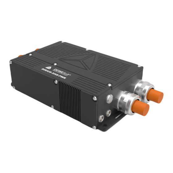
Page 35: Siriusi-Xhs-Pwr Devices
SIRIUSi-XHS-PWR TECHNICAL REFERENCE MANUAL 5. SIRIUSi-XHS-PWR Devices 5.1. SIRIUSi-XHS-PWR-1xHV-1xDC-CT-1000A-UNI Image 32: SIRIUSi-XHS-PWR-1xHV-1xDC-CT-1000A-UNI 5.1.1. SIRIUSi-XHS-PWR-1xHV-1xDC-CT-1000A-UNI specifications SIRIUSi-XHS-PWR specifications SIRIUSi-XHS-PWR-1xHV-1xDC-CT-1000A-UNI Input types Voltage, Current (single phase) Inputs Voltage ADC Type Hybrid ADC - alias free up to 2 MS/s, 16-bit up to 15 MS/s... - Page 36 Flatness 50 Hz - 1 kHz Overall accuracy @ 25°C typ. 20 mdB HV harness Cable size (single core) 120 mm2 95 mm2 70 mm2 50 mm2 35 mm2 Rated DC current 344 A 292 A 245 A 198 A 158 A Cable gland M32 SIRIUSi-XHS-PWR V22-1 36 / 79...
- Page 37 2) ±2000 A is measuring range. Unit can withstand peak value of 2000 A for 100 ms with 1 s recovery time. 3) At the Power Supply lower than 12 V, the maximum measuring current is limited to ±850 A SIRIUSi-XHS-PWR V22-1 37 / 79...
-
Page 38: Siriusi-Xhs-Pwr-1Xhv-1Xdc-Ct-1000A-Uni Technical Drawing
SIRIUSi-XHS-PWR TECHNICAL REFERENCE MANUAL 5.1.2. SIRIUSi-XHS-PWR-1xHV-1xDC-CT-1000A-UNI Technical drawing Image 33: SIRIUSi-XHS-PWR-1xHV-1xDC-CT-1000A dimensions 5.1.3. SIRIUSi-XHS-PWR-1xHV-1xDC-CT-1000A-UNI HV parts Device No. of Size of Cable No. of Cable size cable cable type cables glands gland M32x1.5 60 - 120 mm Single SIRIUSi-XHS-PWR-1xHV-1xDC-CT-1000A-UNI core... -
Page 39: Siriusi-Xhs-Pwr-1Xhv-1Xdc-Ct-1000A-Con
SIRIUSi-XHS-PWR TECHNICAL REFERENCE MANUAL 5.2. SIRIUSi-XHS-PWR-1xHV-1xDC-CT-1000A-CON Image 34: SIRIUSi-XHS-PWR-1xHV-1xDC-CT-1000A-UNI 5.2.1. SIRIUSi-XHS-PWR-1xHV-1xDC-CT-1000A-CON specifications SIRIUSi-XHS-PWR specifications SIRIUSi-XHS-PWR-1xHV-1xDC-CT-1000A-CON Input types Voltage, Current (single phase) Inputs Voltage ADC Type Hybrid ADC - alias free up to 2 MS/s, 16-bit up to 15 MS/s Sampling Rate Simultaneous 15 MS/s... - Page 40 Flatness 50 Hz - 1 kHz Overall accuracy @ 25°C typ. 20 mdB HV connectors PowerLok 500 Series Device connectors PL00X-501-10D10-2 (+), PL00Y-501-10D10-2 (-) Mating connectors (cable) PL18X-501-?-2-5 (+), PL18Y-501-?-2-5 (-) (see3) General specifications Power SIRIUSi-XHS-PWR V22-1 40 / 79...
- Page 41 2) ±2000 A is measuring range. Unit can withstand peak value of 2000 A for 100 ms with 1 s recovery time. 3) ? denotes HV cable size, e.g. PL18X-501-95-2-5 is designed for 95mm2 cable cross-section 4) At the Power Supply lower than 12 V, the maximum measuring current is limited to ±850 A SIRIUSi-XHS-PWR V22-1 41 / 79...
-
Page 42: Siriusi-Xhs-Pwr-1Xhv-1Xdc-Ct-1000A-Con Technical Drawing
SIRIUSi-XHS-PWR TECHNICAL REFERENCE MANUAL 5.2.2. SIRIUSi-XHS-PWR-1xHV-1xDC-CT-1000A-CON Technical drawing Image 35: SIRIUSi-XHS-PWR-1xHV-1xDC-CT-1000A dimensions SIRIUSi-XHS-PWR V22-1 42 / 79... -
Page 43: Siriusi-Xhs-Pwr-1Xhv-1Xdc-Ct-250A-Uni
SIRIUSi-XHS-PWR TECHNICAL REFERENCE MANUAL 5.3. SIRIUSi-XHS-PWR-1xHV-1xDC-CT-250A-UNI Image 36: SIRIUSi-XHS-PWR-1xHV-1xDC-CT-250A-UNI 5.3.1. SIRIUSi-XHS-PWR-1xHV-1xDC-CT-250A-UNI specifications SIRIUSi-XHS-PWR specifications SIRIUSi-XHS-PWR-1xHV-1xDC-CT-250A-UNI Input types Voltage, Current (single phase) Inputs Voltage ADC Type Hybrid ADC - alias free up to 2 MS/s, 16-bit up to 15 MS/s Sampling Rate Simultaneous 15 MS/s... - Page 44 Flatness DC - 50 Hz Overall accuracy @ 25°C typ. 5 mdB Flatness 50 Hz - 1 kHz Overall accuracy @ 25°C typ. 20 mdB Cable size (multi core) 6 mm2 Rated DC current 54 A General specifications Power SIRIUSi-XHS-PWR V22-1 44 / 79...
-
Page 45: Siriusi-Xhs-Pwr-1Xhv-1Xdc-Ct-250A Technical Drawing
1) ±2000 V is measuring range. Device is designed according to IEC 61010-1. Maximum conitnuous working voltage is 1000 VDC or 1000 VAC. 2) ±500 A is measuring range. Maximum current is limited with specified rated current of HV harness (connectors and cables). 5.3.2. SIRIUSi-XHS-PWR-1xHV-1xDC-CT-250A Technical drawing Image 37: SIRIUSi-XHS-PWR-1xHV-1xDC-CT-250A-UNI dimensions 5.3.3. SIRIUSi-XHS-PWR-1xHV-1xDC-CT-250A-UNI HV parts Device No. -
Page 46: Siriusi-Xhs-Pwr Connectors
225VA) 5.4. SIRIUSi-XHS-PWR connectors SIRIUSi-XHS-PWR provides power supply, data interface and synchronization in just one cable. CAN connection demands additional cable. 5.4.1. SIRIUSi-XHS-PWR: Power, Data, SYNC: L1T8m Power supply, data interface (GbE) and synchronization (PTPv2) are enabled via a single cable connected to the LEMO 1T series 8-pin connector on the device. -
Page 47: Siriusi-Xhs-Pwr: Can: D9M (Default)
SIRIUSi-XHS-PWR TECHNICAL REFERENCE MANUAL 5.4.2.1. SIRIUSi-XHS-PWR: CAN: D9m (default) Name Description Reserved for 5V CAN_LOW CAN low GND_CAN Digital Ground Isolated Clock_sync Clock sync pin PPS sync Sync GND CAN_HIGH CAN high Image 39: CAN connector: pin-out (DSUB-9 male) Trig_Sync... -
Page 48: Siriusi-Xhs-Pwr: Can: F102S7F (Optional)
SIRIUSi-XHS-PWR TECHNICAL REFERENCE MANUAL 5.4.2.2. SIRIUSi-XHS-PWR: CAN: F102S7f (optional) Name Description Reserved CAN_H CAN high CAN_L CAN low Power + Power supply, plus Power + Power supply, plus Image 40: CAN connector: pin-out (Fischer DEU 102 A055-SC) Power GND Power supply... -
Page 49: Magnitude Response
SIRIUSi-XHS-PWR TECHNICAL REFERENCE MANUAL 5.5. Magnitude response 5.5.1. Voltage measurement Image 41: Magnitude response of HV input in high-bandwidth mode SIRIUSi-XHS-PWR V22-1 49 / 79... - Page 50 SIRIUSi-XHS-PWR TECHNICAL REFERENCE MANUAL Image 42: Magnitude response of HV input using 1 MHz LP filter Image 43: Magnitude response of HV input in high-dynamic mode SIRIUSi-XHS-PWR V22-1 50 / 79...
-
Page 51: Current Measurement
SIRIUSi-XHS-PWR TECHNICAL REFERENCE MANUAL 5.5.2. Current measurement Image 44: Magnitude response of DC-CT input SIRIUSi-XHS-PWR V22-1 51 / 79... -
Page 52: Uni Cabling Instructions
TECHNICAL REFERENCE MANUAL 6. UNI cabling instructions 6.1. SIRIUSi-XHS-PWR-1xHV-1xDC-CT-1000A-UNI assembly instructions Congratulations! A. Unscrew 6x T20 (M4x8) screws on the You are the owner of SIRIUSi-XHS-PWR DAQ orange cover. device. B. Remove orange aluminum cover. A. Remove the protection lid (PCB-COVER). - Page 53 A. Crimp HV cables and shield according to crimping recommendations B. Place HV cables through cable glands. A. Place the SHIELD cable from HV- cable to A. Place the SHIELD cable from HV+ cable to the SHIELD Busbar_B the SHIELD Busbar_A SIRIUSi-XHS-PWR V22-1 53 / 79...
- Page 54 B. Mount SHIELD cables with 4x H5 M4x8 screws according to the mounting recommendations A. Place back orange aluminum cover. Congratulations! B. Screw back 6x T20 (M4x8) screws from You are ready to measure! STEP 2. SIRIUSi-XHS-PWR V22-1 54 / 79...
-
Page 55: Siriusi-Xhs-Pwr-1Xhv-1Xdc-Ct-250A-Uni Assembly Instructions
SIRIUSi-XHS-PWR TECHNICAL REFERENCE MANUAL 6.2. SIRIUSi-XHS-PWR-1xHV-1xDC-CT-250A-UNI assembly instructions Congratulations! A. Unscrew 6x T20 (M4x8) screws on the You are the owner of SIRIUSi-XHS-PWR DAQ orange cover. device. B. Remove orange aluminum cover. A. Remove the protection lid (PCB-COVER). A. Crimp the multicore cable according to crimping recommendations B. - Page 56 SIRIUSi-XHS-PWR TECHNICAL REFERENCE MANUAL A. Place back protection lid (PCB-COVER). A. Place back orange aluminum cover. A. Screw back 6x T20 (M4x8) screws from Congratulations! STEP 2. You are ready to measure! SIRIUSi-XHS-PWR V22-1 56 / 79...
-
Page 57: Crimping Recommendations
Hint Use a crimping tool and crimping dies that fit to cable lugs. There is a difference between the DIN-series and R-series standard of crimping dies and cable lugs. At Dewesoft HQ, we use crimping solutions from Intercable . - Page 58 SIRIUSi-XHS-PWR TECHNICAL REFERENCE MANUAL SIRIUSi-XHS-PWR V22-1 58 / 79...
- Page 59 SIRIUSi-XHS-PWR TECHNICAL REFERENCE MANUAL SIRIUSi-XHS-PWR V22-1 59 / 79...
- Page 60 5. Place a thermal insulation sleeve on the shield - ready for crimping. Cable size (mm2) A (mm) B (mm) Caution Shielding braid shall not be cut or broken during the cutting procedure. Shielding braid should be combed out. SIRIUSi-XHS-PWR V22-1 60 / 79...
-
Page 61: Mounting Recommendations
Mounting of the shield is performed with H5 M6 hex key screws. Recommended torque for bolted joints is 7.2 Nm . Important Mounting of the high-voltage conductor cables and shield should be done using a torque wrench. SIRIUSi-XHS-PWR V22-1 61 / 79... -
Page 62: Filtering
SIRIUSi-XHS-PWR TECHNICAL REFERENCE MANUAL 7. Filtering SIRIUSi-XHS-PWR features Hybrid ADC technology. Some channels can be selected as high bandwidth others as high dynamic - signals are still perfectly time aligned with zero phase shift. User can select three different filtering modes in DewesoftX software: Off (Full High-bandwidth mode) ●... -
Page 63: High-Bandwidth Mode: Analog Aaf 1 Mhz Lpf
7.2. High-bandwidth mode: Analog AAF 1 MHz LPF Image 46: Typical frequency response in high-bandwidth mode with analog anti-aliasing filter (1MHz) 7.3. High-dynamic mode: AAF Image 47: Typical frequency response in high-dynamic mode with anti-aliasing filter (AAF) - Magnitude in dB. SIRIUSi-XHS-PWR V22-1 63 / 79... - Page 64 SIRIUSi-XHS-PWR TECHNICAL REFERENCE MANUAL Image 48: Typical frequency response in high-dynamic mode with anti-aliasing filter (AAF) - Normalized amplitude. SIRIUSi-XHS-PWR V22-1 64 / 79...
-
Page 65: Accessories
TECHNICAL REFERENCE MANUAL 8. Accessories 8.1. ETH-POWER-JUNCTION ETH-POWER-JUNCTION combines data and power line for the SIRIUSi-XHS-PWR device. It is intended to be used with a single SIRIUSi-XHS-PWR unit. Warning Current limit of ETH-POWER-JUNCTION is 3 A. It can be also used with EtherCAT devices, such as KRYPTON. -
Page 66: Eth-Power-Junction Specifications
Power supply 9-48 V DC, LEMO 1B 2-pin male connector (EXJ.1B.302.HLD) PWR + DATA OUT L1B8f Combined power and data. Connection to (EXG.1B.308.HLN) SIRIUSi-XHS-PWR device using L1B8m-L1T8f-CAT7-Xm cable. DATA IN RJ45 Data transfer to SBOX, data logger or PC using RJ45-Xm cable.. -
Page 67: Ds-6Xlan-L1B
LEMO 1B Series 8-pin connectors with combined power and data. Uplink ports are RJ45. Warning Current limit of DS-6xLAN-L1B is 3 A per channel. Total current limit of DS-6xLAN-L1B is 15 A. Image 50: DS-6xLAN-L1B switch SIRIUSi-XHS-PWR V22-1 67 / 79... -
Page 68: Ds-6Xlan-L1B Specifications
Regulatory Compliance EN61000 IEC60068-2-32 (free fall) IEC60068-2-27 (shock) Stability Testing IEC60068-2-6 (vibration) IEEE 1588v2 PTP Peer-to-peer Standards Compliance End-to-end Environment Operating Temperature -40 to 70°C Storage Temperature -40 to 85°C Humidity 5 ~ 95% (non-condensing) SIRIUSi-XHS-PWR V22-1 68 / 79... -
Page 69: Ds-6Xlan-L1B Connectors
Connector Description FRONT PANEL connectors L1B8f 4x GbE downlink ports. Combined power and data outputs. (EXG.1B.308.HLN) Connection to SIRIUSi-XHS-PWR devices using L1B8m-L1T8f-CAT7-Xm cable. BACK PANEL connectors POWER IN L1B2m Power supply 9-48 V DC, LEMO 1B 2-pin male connector. (EXJ.1B.302.HLD) -
Page 70: Ds-6Xlan-Rj45
LEMO 1B Series 8-pin connectors with combined power and data. Uplink ports are RJ45. Warning Current limit of DS-6xLAN-L1B is 3 A per channel. Total current limit of DS-6xLAN-L1B is 15 A. Image 51: DS-6xLAN-RJ45 switch SIRIUSi-XHS-PWR V22-1 70 / 79... -
Page 71: Ds-6Xlan-Rj45 Specifications
Regulatory Compliance EN61000 IEC60068-2-32 (free fall) IEC60068-2-27 (shock) Stability Testing IEC60068-2-6 (vibration) IEEE 1588v2 PTP Peer-to-peer Standards Compliance End-to-end Environment Operating Temperature -40 to 70°C Storage Temperature -40 to 85°C Humidity 5 ~ 95% (non-condensing) SIRIUSi-XHS-PWR V22-1 71 / 79... -
Page 72: Ds-6Xlan-Rj45 Connectors
M3 insert for grounding. 8.4. D9fw-D9m-L00B4f-Xm-CAN-SYNC The CAN-SYNC adapter cable combines CAN and sync signals on the DB9 connector. It gives the user an option to output IRIG signal from the SIRIUSi-XHS-PWR device. Image 52: D9fw-D9m-L00B4f-Xm-CAN-SYNC adapter cable SIRIUSi-XHS-PWR V22-1... -
Page 73: Connectors
TECHNICAL REFERENCE MANUAL 8.4.1. Connectors Name Connector Description CAN-SYNC Combo CAN+SYNC connector for connection to SIRIUSi-XHS-PWR device. Connection to SIRIUSi-XHS-PWR unit is IP67 rated. For reading the CAN data Sync L004f To output various synchronization source, such as IRIG-B-DC SIRIUSi-XHS-PWR V22-1... -
Page 74: Order Codes
MS/s; Power supply: 9-60 V DC on L1T8m connector (Power+Data+Sync); 1x CAN 2.0b BUS isolated on DSUB9m; Synchronization: IEEE 1588v2 PTP; IP rating: IP67; Dewesoft-X included; HV connectors: Amphenol PL 500 Series DS-6xLAN-L1B DS-6xLAN-L1B 6-port network switch; Downlink (PWR+DATA): 4x up to 1 Gbps: 4x L1B8f (front panel);... - Page 75 SIRIUSi-XHS-PWR TECHNICAL REFERENCE MANUAL Cable length: 10 m L00B4m-L00B4m-Xm Sychronization cable; Fits to: All Dewesoft devices with L00B4m sync connector; Cable length: Xm CL-SET-120 Cable lug set; 120 mm2 HV harness; 4x cable lugs (Part number: ICF1206S); M6 mount; Used with SIRIUSi-XHS-PWR-1xHV-1xDC-CT-1000A-UNI CL-SET-95 Cable lug set;...
-
Page 76: General Product Information And Instructions
10.1. Environmental Considerations Information about the environmental impact of the product. 10.2. Product End-of-Life Handling Observe the following guidelines when recycling a Dewesoft system: System and Components Recycling Production of these components required the extraction and use of natural resources. The substances... -
Page 77: Notice
Dewesoft system can be requested. We retain them for at least one year, after system delivery. 11.3. Support Dewesoft has a team of people ready to assist you if you have any questions or any technical difficulties regarding the system. For any support please contact your local distributor first or Dewesoft directly. -
Page 78: Copyright
When used in text representing the company, product or technology name, the ® sign is not used. The Dewesoft triangle logo is a registered trademark but the ® sign is not used in the visual representation of the triangle logo. -
Page 79: Documentation Version History
Updated: Safety General product information and instructions V21-2 03.11.2021 Updated: 3.2. Connecting SIRIUSi-XHS-PWR (schematics updated) 3.2.4.1. Autodetect (added chapter) 3.2.4.1. Autodetect (added chapter) 4. System overview (updated image and subchapters with Key features) 5. Specification 5.1.1. SIRIUSi-XHS-PWR-1xHV-1xDC-CT-1000A specifications (updated) 5.1.2. SIRIUSi-XHS-PWR-1xHV-1xDC-CT-500A specifications (added) 5.1.3.
Need help?
Do you have a question about the SIRIUSi-XHS-PWR and is the answer not in the manual?
Questions and answers