
Related Manuals for Megger TRAX


Summary of Contents for Megger TRAX
- Page 1 TRAX Transformer and Substation Test System User’s Manual Art No. ZP-AJ01E Doc. AJ0383BE V02b 2015...
- Page 3 © 2015, Megger Sweden AB. All rights reserved. The contents of this manual are the property of Megger Sweden AB. No part of this work may be reproduced or transmitted in any form or by any means, except as permitted in written license agreement with Megger Sweden AB. Megger Sweden AB has made every reasonable attempt to ensure the completeness and accuracy of this document.
-
Page 4: Table Of Contents
..........35 ............. 16 Safety ............... 35 4.1 Start-up screen ..........16 Step-by-step instructions ........... 35 Turn off TRAX ............16 5 Data handling and reporting ..... 36 Global settings ............16 5.1 General ............36 GUI Settings ............16 5.2 Test object configuration ......36 Instruments ............... - Page 5 6.2 Remote control ..........40 Connecting a device to TRAX ........40 Simulation mode ............40 7 Upgrading TRAX ............. 42 7.1 Upgrading ..........42 Upgrading via Internet ..........42 Upgrading via USB ............ 42 8 Specifications ............. 44 Specifications TRAX .........44 Index ............
-
Page 6: Introduction
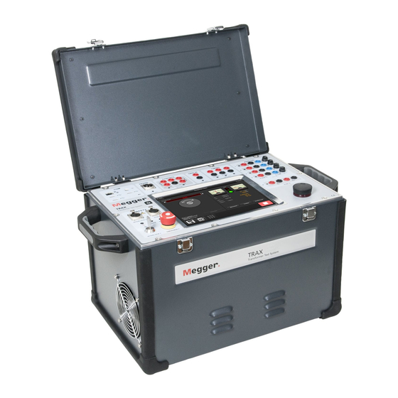
1 INTRODUCTION Introduction 1.1 Product description 1.2 Features and benefits TRAX is a unique test system for testing power ▪ Multi function system for transformer/substation transformers, CTs, VTs, and many other substation testing components. A variety of voltage and current levels ▪... -
Page 7: Warranty
Megger of any shortage. ▪ Examine the instrument for damage received in transit. If damage is discovered, file a claim with the carrier at once and notify Megger, giving a detailed description of the damage. ▪ This instrument has been thoroughly tested and inspected to meet rigid specifications before being shipped. -
Page 8: Safety
Detector will indicate that the separate to be connected to station ground using a GROUND on the side panel is not con- separate ground cable (not via TRAX unit!) nected to ground. ▪ In compliance with local safety regulations and permits, use a temporary grounding and... -
Page 9: Safety Instructions
Persons with heart pacemakers should obtain expert advice on the possible risks before operating this equipment or being close to the equipment during operation. AJ0383BE ZP-AJ01E TRAX... -
Page 10: Maintenance
Observe all safety warnings marked on the equipment. Corrective maintenance must only be performed by qualified personnel who are familiar with the design and operation of the test set and the hazards involved. TRAX ZP-AJ01E AJ0383BE... - Page 11 3 CONTROLS, INDICATORS AND CONNECTORS AJ0383BE ZP-AJ01E TRAX...
-
Page 12: Controls, Indicators And Connectors
WARNING 6. 0-200 A AC / 0-800 A AC The outputs 2 and 6 are connected inter- TRAX 220: 0-200 A (6 V), TRAX 208: 0-800 A (6 V) nally to the same output transformer and 7. AUX CONTROL should be considered “live” when one of Ethernet communication and power (54 V DC) to accessories. -
Page 13: Top Panel
(e.g. 1 V, 2 V, 5 V, 0.1 V). start. Press for 3 seconds and the instrument will Also used as pairing device when connecting shut off. TRAX for external control via Ethernet or Wifi. 9. STROBE External strobe is optional, but when connected, Communication and safety it will flash while generating voltage/current. -
Page 14: Analog Inputs
16 A DC current outputs. If the units are used for measuring AC, max input is 40 V RMS. 5. LED INDICATORS Red LED’s indicate which channel to connect to depending on what software instruments is used. TRAX ZP-AJ01E AJ0383BE... - Page 15 4 OPERATING INSTRUCTIONS AJ0383BE ZP-AJ01E TRAX...
-
Page 16: Operating Instructions
4 OPERATING INSTRUCTIONS Operating instructions 4.1 Start-up screen Restart the TRAX SW (but not the HW) Press for one second to turn on TRAX. Note When TRAX is operated from a PC, shortcut key F5 can also be Restart used for restart Information;... -
Page 17: Instruments
4 OPERATING INSTRUCTIONS Network Line 60, 50, 25 or 16 2/3 Hz frequency Settings for TRAX remote operation. Not available Test by Test tables are organized by tap or in offline mode. winding. Reversed Test tables are organized with mid-... - Page 18 4 OPERATING INSTRUCTIONS My TRAX In “My TRAX”you can place TRAX Excitation current instrument is your favourite instruments used for measuring current and im- for easy access. pedance on one side of a transformer Exitation Power Transformer Instruments suitible for with the opposite windings open.
-
Page 19: Manual Control
Output generators and input channels can be selected to perform a variety of measurements. Saves the test results to report/file. If it is the first test TRAX will ask for filename and location All generators and analog measurement Starts a new test for the same test session. -
Page 20: Control Knob
Select “Manual” or “Ramp”. Press to select measurement channels. In manual mode the generator is started instantly. A max generating time can be set. In ramp mode, the output signal amplitude is increased continuously, hold at the set value and TRAX ZP-AJ01E AJ0383BE... - Page 21 Freq Narrow-band data for the selected measured by TRAX, e.g. active current clamps (current frequency to voltage). Rectified Mean Value of signal multiplied by 1.11 to equivalent RMS...
- Page 22 Press “Freeze” to hold and show the oscillo- scope picture Start/Stop measurements Press to start the measurement. Output signals and selected measurement signals are continuously displayed on the analog meters and in the results fields. TRAX ZP-AJ01E AJ0383BE...
-
Page 23: Manual Control Application Examples
10 μΩ – 5 Ω cables until the winding is discharged and the TRAX “active” indicator stops flash- Press ing. Select “R” > “R1” > “DC” In case of a power breakdown during a measurement or a discharge process, TRAX will still continue discharging. -
Page 24: Excitation Current (Impedance) Measurements
Connect the other two windings of the Short-circuit/leakage reactance transformer in parallel with the first winding (e.g. for a YNyn transformer A-B-C should be measurements connected in parallel). Select 0-10 A generator. TRAX ZP-AJ01E AJ0383BE... -
Page 25: Power Transformer Turns-Ratio Measurements
Select an appropriate test voltage, best accu- racy is achieved at about 75% of saturation Make sure that one side of primary winding P1/H1 OR P2/H2 is floating (other side may be voltage. connected to ground). Press to start the generating. AJ0383BE ZP-AJ01E TRAX... -
Page 26: Ct Ratio With Current
The test mode is GST-GND which means that the total current to ground will be measured. The test result will be affected by all stray Select 0-200 A (or 0-800 A if TRAX 280) gen- capacitors including e.g. cables and surface erator. -
Page 27: Contact Resistance
1, 2, 3 or 4 frequency Press “OK”. Select desired “Test current” and “Genera- tor”. After selection the test current can be adjust- ed within the actual current range. Select “Continuous” if desired. Single test is default. AJ0383BE ZP-AJ01E TRAX... -
Page 28: Connection For Measurement
Typical test currents are 1-15% and using 5-15% will give fast and stable readings. Controls for tap changer operation The CONTROL contacts are used to remotely operate the tap-changer. TRAX ZP-AJ01E AJ0383BE... -
Page 29: Settings
2 seconds before the next operation is stopped. possible. Demag When activated, TRAX suggest to warning do demagnetization when the WRM Run two wires from each contact and connect in app is to be closed. -
Page 30: Connection For Measurement
Stop generator. Operate tap changer. Start generating, when reading is stable, stop measurement and the result is displayed Repeat from step 2 until last tap. Reconnect cables and perform test on next phase. TRAX ZP-AJ01E AJ0383BE... -
Page 31: Demagnetization
Operate tap changer. If discontinuity, TRAX Always comply with local safety regula- will automatically stop the test and discharge tions. the winding, if continuity TRAX is starting measurements on the next tap. Press Continue until last tap. Stop generator/capture data when the read- ing is stable. -
Page 32: Transformer Turns Ratio
Always comply with local safety regula- tions. Press TRAX turns ratio app determines the transformer turns-ratio as defined by international standards. The instrument provides an excitation test voltage to the primary windings of the transformer and measures simultaneously the voltage at the corresponding secondary winding. -
Page 33: Step-By-Step Instructions
In case the calculated tap voltage differs from the nameplate it is possible to manually enter the values in the table. Press to display a connecting diagram. Connect cables. AJ0383BE ZP-AJ01E TRAX... -
Page 34: Excitation Current
Select what generator to use, 250 V AC or 2200 V AC. Connect cables to the test object as described TRAX Excitation current instrument is intended for in the table and connection picture. measuring current and impedance on one side of a Press to start the first test. -
Page 35: Short-Circuit Impedance / Leakage Reactance
Manual Control. Per-phase measurements When configuration is selected, TRAX suggest measurements per-phase and the variation in leakage reactance, Xs, is calculated and displayed. Three-phase equivalent By selecting “Impedance” the instrument auto-... -
Page 36: Data Handling And Reporting
17 taps, the consecutive tests will automatically have the same configuration. Test configuration ▪ A test session is started when TRAX is started and In many situations it is advisable and sometimes finished when TRAX is closed or when the user mandatory to enter the test object configuration, e.g. -
Page 37: Save And Report
Deleting file. Can only be used if the file folder is unlocked Create new folder Load files from TRAX or PC: (remote control only). Press “Filename” to enter the name. Refresh folder content Press “OK” button to save the file. -
Page 38: Report View
5 DATA HANDLING AND REPORTING Export TRAX file in *.xml format Export TRAX report in text format for e.g. Excel import Activates / deactivates the buttons described in the table below The report may contain several tests Press the actual icon to open the file in re- on multiple pages. -
Page 39: Trax Logfile
5 DATA HANDLING AND REPORTING 5.4 TRAX logfile The logfiles are accessed via “Logging” in the home menu. The files are organized by instruments. Logfiles can be downloaded to USB or PC with the upper right button. Filename is *.log. Format is tab delimited text and the files can be directly imported as data from text in Excel. -
Page 40: Remote Control And Communication Ports
(normally by displaying a “?” in your network symbol) Start TRAX Control. After a while, the screen will display all TRAX units found on the network. Select the unit you want to connect to. A dialog is started where you are asked to... - Page 41 7 UPGRADING TRAX AJ0383BE ZP-AJ01E TRAX...
-
Page 42: Upgrading Trax
7 UPGRADING TRAX Upgrading TRAX 7.1 Upgrading TRAX SW can be upgraded via Internet or with a USB stick. Upgrading via Internet Connect TRAX to an open Internet port with unlimited access. From the home page select “Settings” and “Update”. - Page 43 8 SPECIFICATIONS AJ0383BE ZP-AJ01E TRAX...
-
Page 44: Specifications
8 SPECIFICATIONS Specifications Specifications TRAX 0-800 A 0-800 A/6 V, 30 s TRAX280 0-250 A/10 V, 1 min Specifications are valid at nominal input voltage and an ambient Frequency range: temperature of +25°C ±5°, (77°F). Specifications are subject to 45-70 Hz change without notice. - Page 45 TRAX specification is valid at 230-240 V mains voltage. Output power is decreased at lower mains voltages. Derating at high ambient temperature TRAX specification is valid at 23 ±5°C. Max ouput current times will be reduced when using TRAX in high ambient temperature Measurement accuracy External 0.05% of reading + 0.05% FS...
-
Page 46: Index
Test object configuration ........ 36 GUI Settings ..........16 Top panel ............13 Transformer turns ratio ........32 impedance ............. 24 Turn off TRAX ..........16 Indicators ............12 Instrument description ........18 Upgrading ............42 Instruments ............ 17 Instrument safety ..........8 Instrument settings ........ - Page 48 ▪ Insulation Power Factor (C&DF) Test Equipment worldwide. ▪ Insulation Resistance Test Equipment Megger is certified according to ISO 9001 and 14001. ▪ Line Testing Equipment Megger is a registered trademark. ▪ Low Resistance Ohmmeters ▪...
Need help?
Do you have a question about the TRAX and is the answer not in the manual?
Questions and answers